1
Ver 1.0 2003. 07
Model Name Using Similar Mechanism
WM-FX271
Tape Transport Mechanism Type
MF-WMFX171-114
SERVICE MANUAL
US Model
WM-FX271FP
RADIO CASSETTE PLAYER
Frequency range
FM: 87.5 108 MHz
AM: 530 1,710 kHz
Power requirements
3 V DC batteries R6 (AA)
× 2/External DC 3 V power sources
Dimensions
91.4
× 115.5 × 35.9 mm (3 5/8 × 4 5/8 × 1 7/16 inches) (w/h/d) incl.
projecting parts and controls
Mass
Approx. 150 g (5.3 oz.)
Approx. 230 g (8.2 oz.) incl.batteries and a tape
Supplied accessories
Stereo headphones or Stereo earphones (1)
Design and specifications are subject to change without
notice.
SPECIFICATIONS
Sony Corporation
Personal Audio Company
Published by Sony Engineering Corporation
9-961-044-01
2003G04-1
© 2003. 07
Notes on Chip Component Replacement
· Never reuse a disconnected chip component.
· Notice that the minus side of a tantalum capacitor may be dam-
aged by heat.
Flexible Circuit Board Repairing
· Keep the temperature of the soldering iron around 270°C during
repairing.
· Do not touch the soldering iron on the same conductor of the
circuit board (within 3 times).
· Be careful not to apply force on the conductor when soldering
or unsoldering.

2
TABLE OF CONTENTS
1. GENERAL ........................................................................... 3
2. DISASSEMBLY
2-1. Cabinet (Front) Sub Assy .................................................... 4
2-2. Main Board ......................................................................... 5
2-3. Holder (Sub) Assy, Cassette ................................................ 5
2-4. Mechanism Deck ................................................................. 6
2-5. Belt and Motor .................................................................... 6
3. MECHANICAL ADJUSTMENTS ................................. 7
4. ELECTRICAL ADJUSTMENTS
Tape Section ............................................................................ 7
Tuner Section ........................................................................... 8
5. DIAGRAMS
5-1. IC Pin Description ............................................................. 10
5-2. Block Diagram .................................................................. 11
5-3. Printed Wiring Board ........................................................ 12
5-4. Schematic Diagram ........................................................... 13
6. EXPLODED VIEWS
6-1. Cabinet Section ................................................................. 15
6-2. Tape Mechanism Section-1 ............................................... 16
6-3. Tape Mechanism Section-2 ............................................... 17
7. ELECTRICAL PARTS LIST ........................................ 18
WM-FX271FP
z
UNLEADED SOLDER
Boards requiring use of unleaded solder are printed with the lead
free mark (LF) indicating the solder contains no lead.
(Caution: Some printed circuit boards may not come printed with
the lead free mark due to their particular size.)
: LEAD FREE MARK
Unleaded solder has the following characteristics.
· Unleaded solder melts at a temperature about 40°C higher than
ordinary solder.
Ordinary soldering irons can be used but the iron tip has to be
applied to the solder joint for a slightly longer time.
Soldering irons using a temperature regulator should be set to
about 350°C.
Caution: The printed pattern (copper foil) may peel away if the
heated tip is applied for too long, so be careful!
· Strong viscosity
Unleaded solder is more viscous (sticky, less prone to flow)
than ordinary solder so use caution not to let solder bridges
occur such as on IC pins, etc.
· Usable with ordinary solder
It is best to use only unleaded solder but unleaded solder may
also be added to ordinary solder.
3
WM-FX271FP
SECTION 1
GENERAL
This section is extracted
from instruction manual.
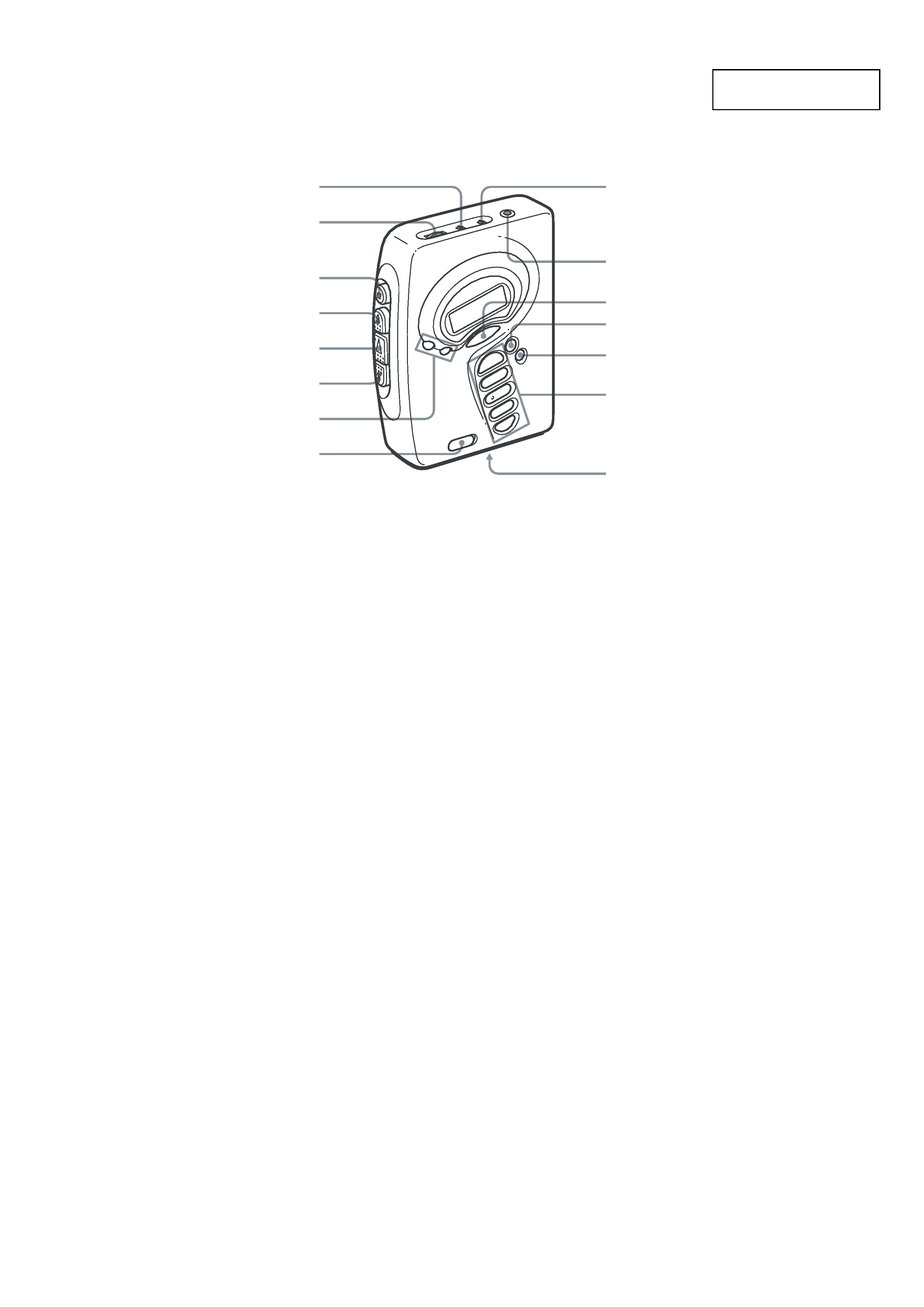
AVLS
VOLUME
x STOP
M FF
N PLAY
m REW
TUNING +/
HOLD
i
MEGA BASS
RADIO ON/OFF
BAND
DC IN 3V
NORM/CrO2/METAL
DX/LOCAL or
NORM/CrO2/METAL
ST/FM MONO
1-5 (preset)
*
* The button has a tactile dot.
Location of parts and controls
4
WM-FX271FP
SECTION 2
DISASSEMBLY
· The equipment can be removed using the following procedure.
Note : Follow the disassembly procedure in the numerical order given.
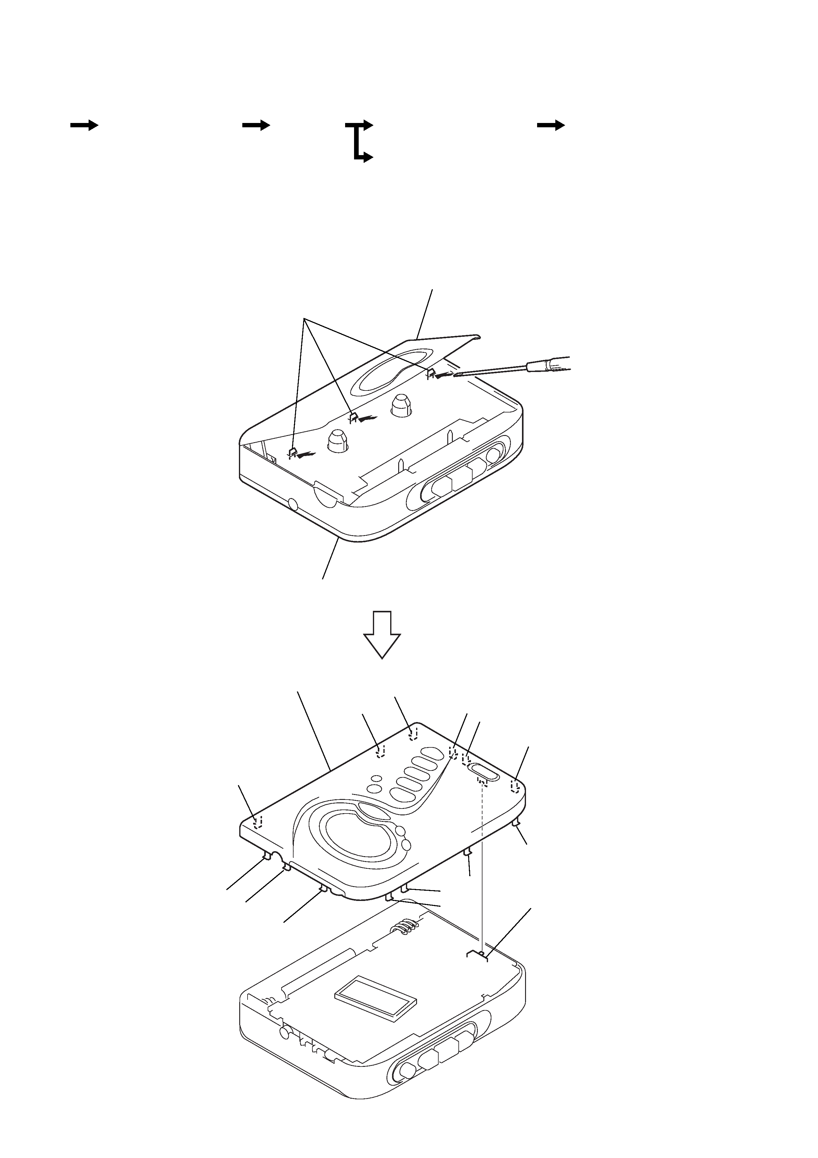
2-1. CABINET (FRONT) SUB ASSY
Note : When installing, fit the knobs and switches.
1
Insert the precision screwdriver
(1.4 mm flat-blade) into the slit
at claw A and release the claw.
2
Remove the cabinet (front) sub assy.
(Release all claws B to N in
alphabetical order.)
Cabinet (front) sub assy
Main board
Set
Holder (sub) assy, cassette
Belt and Motor
Mechanism deck
A
cabinet (front) sub assy
holder (sub) assy, cassette
B
C
D
E
F
H
I
J
K
S716
G
L
M
N
cabinet (front) sub assy
Note : When removing the cabinet, put cloth
on the end of a screwdriver or use a
polyacetal driver to avoid damage to
the cabinet.
5
WM-FX271FP
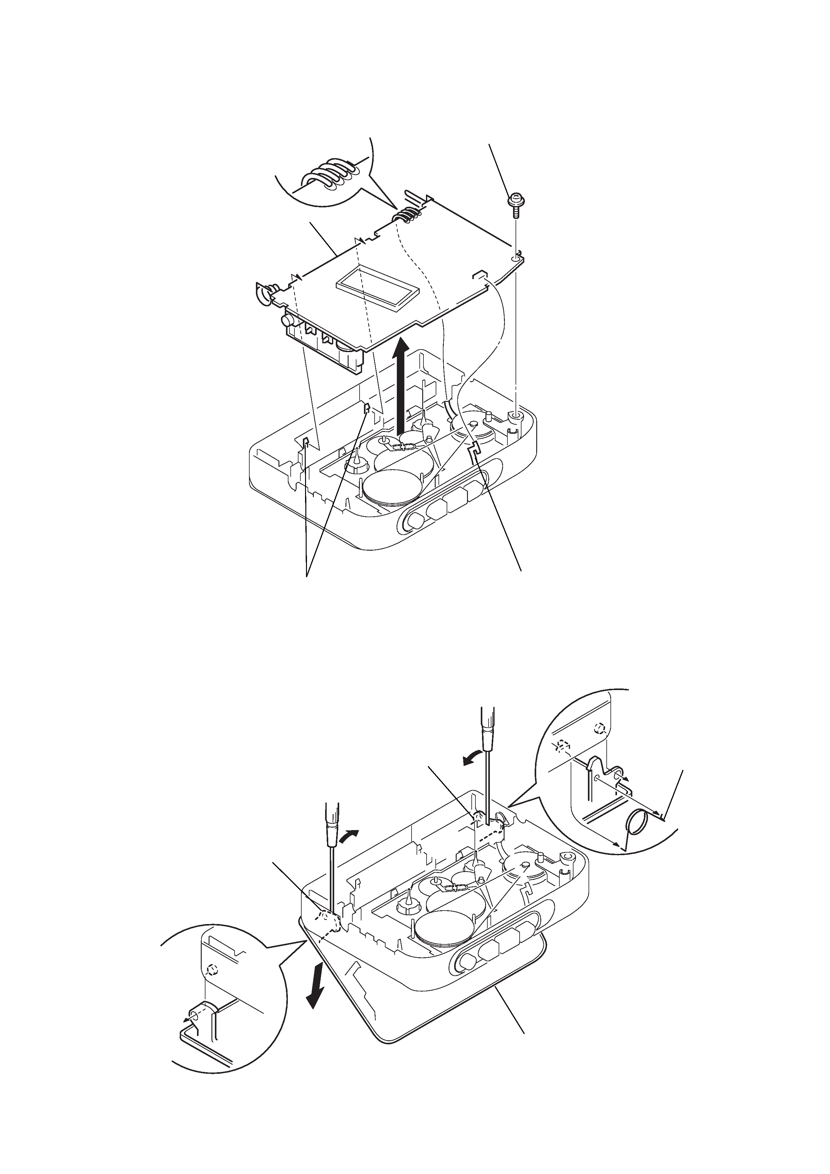
2-2. MAIN BOARD
2-3. HOLDER (SUB) ASSY, CASSETTE
2
Insert a precision screwdriver
(1.4 mm flat-blade) vertically
into portion A to release the
hinge plate.
3
Portion B to release the
hinge plate.
4
two claws
1
HEAD FLEXIBLE board (CN301)
2
Unsolder the 4 places.
5
MAIN board
3
screw (M1.4), toothed lock (WH)
1
Open the holder (sub) assy, cassette.
4
holder (sub) assy, cassette.
A
B
5
spring (torsion)