1
MICROFILM
SERVICE MANUAL
US Model
WM-FX271/FX275
Canadian Model
AEP Model
E Model
Chinese Model
WM-FX271
WM-FX271/FX275
RADIO CASSETTE PLAYER
Photo: WM-FX271
Frequency range
FM: 65 74/87.5 108 MHz (East European)
87.5 108 MHz (Except East European)
AM: 530 1,710 kHz (US, Canadian)
531 1,602 kHz (Except US, Canadian)
Power requirements
3 V DC batteries R6 (AA)
× 2/External DC 3 V power sources
Dimensions
91.4
× 115.5 × 35.9 mm (3 5/8 × 4 5/8 × 1 7/16 inches) (w/h/d) incl.
projecting parts and controls
Mass
Approx. 150 g (5.3 oz.)
Approx. 230 g (8.2 oz.) incl.batteries and a tape
Supplied accessories
Stereo headphones or Stereo earphones (1)/Carrying case (1)
Design and specifications are subject to change without
notice.
SPECIFICATIONS
Model Name Using Similar Mechanism
WM-FX171
Tape Transport Mechanism Type
MF-WMFX171-114
Flexible Circuit Board Repairing
· Keep the temperature of the soldering iron around 270°C during
repairing.
· Do not touch the soldering iron on the same conductor of the
circuit board (within 3 times).
· Be careful not to apply force on the conductor when soldering
or unsoldering.
Notes on Chip Component Replacement
· Never reuse a disconnected chip component.
· Notice that the minus side of a tantalum capacitor may be dam-
aged by heat.
Ver 1.0 1999. 02

2
TABLE OF CONTENTS
1. GENERAL ........................................................................... 3
2. DISASSEMBLY
2-1. Cabinet (Front) Sub Assy .................................................... 4
2-2. Main Board ......................................................................... 5
2-3. Holder (Sub) Assy, Cassette ................................................ 5
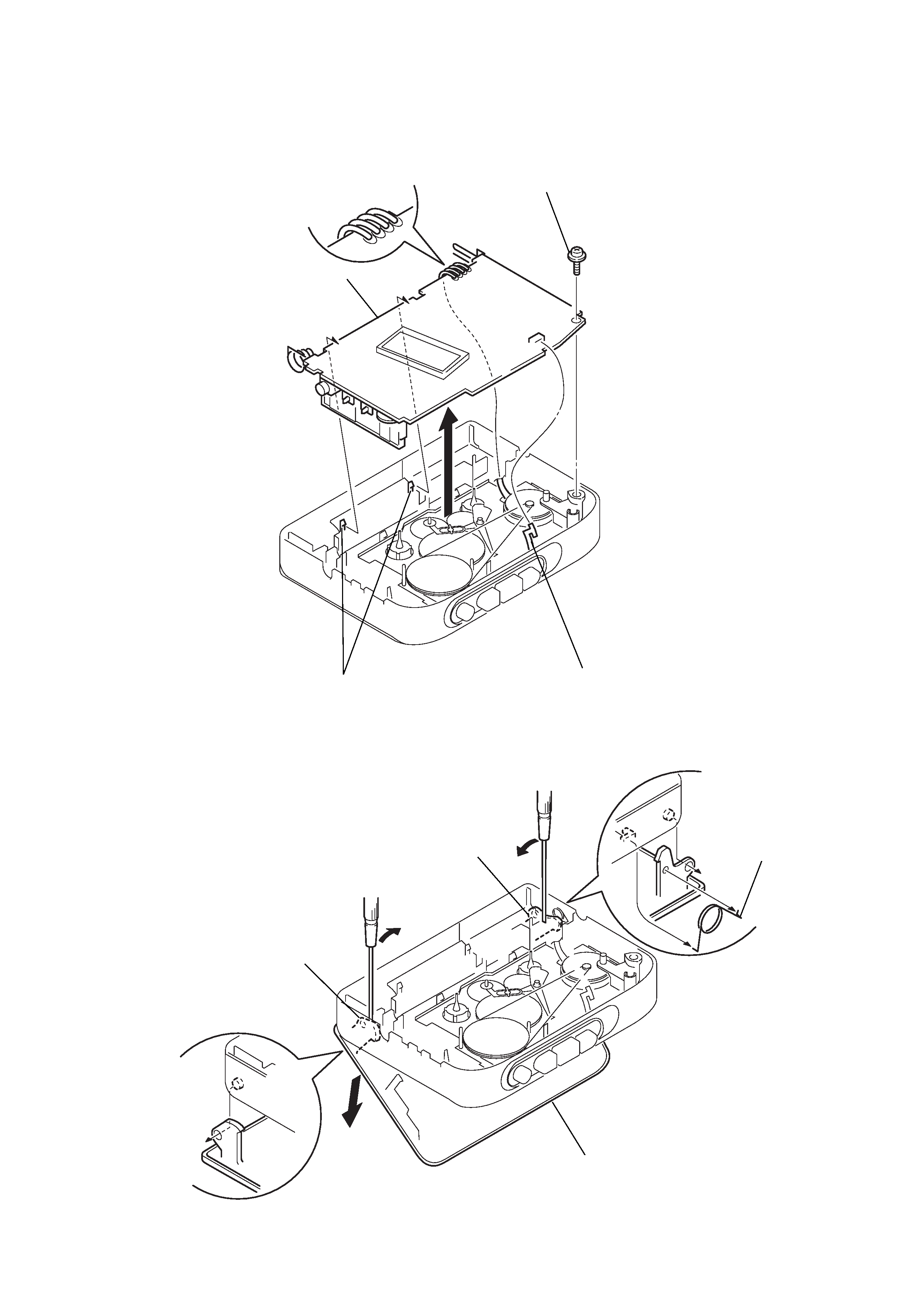
2-4. Mechanism Deck ................................................................. 6
2-5. Belt and Motor .................................................................... 6
3. MECHANICAL ADJUSTMENTS ................................. 7
4. ELECTRICAL ADJUSTMENTS
Tape Section ............................................................................ 7
Tuner Section ........................................................................... 8
5. DIAGRAMS
5-1. IC Pin Description ............................................................. 10
5-2. Block Diagram .................................................................. 11
5-3. Printed Wiring Board ........................................................ 13
5-4. Schematic Diagram ........................................................... 15
6. EXPLODED VIEWS
6-1. Cabinet Section ................................................................. 18
6-2. Tape Mechanism Section-1 ............................................... 19
6-3. Tape Mechanism Section-2 ............................................... 20
7. ELECTRICAL PARTS LIST ........................................ 21
3
SECTION 1
GENERAL
This section is extracted
from instruction manual.
4
SECTION 2
DISASSEMBLY
2-1. CABINET (FRONT) SUB ASSY
Note : When installing, fit the knobs and switches.
Cabinet (front) sub assy
Main board
Set
Holder (sub) assy, cassette
Belt and Motor
Mechanism deck
1 Insert the precision screwdriver
(1.4 mm flat-blade) into the slit
at claw A and release the claw.
2 Remove the cabinet (front) sub assy.
(Release all claws B to N in
alphabetical order.)
· The equipment can be removed using the following procedure.
A
cabinet (front) sub assy
holder (sub) assy, cassette
B
C
D
E
F
H
I
J
K
S716
G
L
M
N
cabinet (front) sub assy
Note : When removing the cabinet, put cloth
on the end of a screwdriver or use a
polyacetal driver to avoid damage to
the cabinet.
Note : Follow the disassembly procedure in the numerical order given.
5
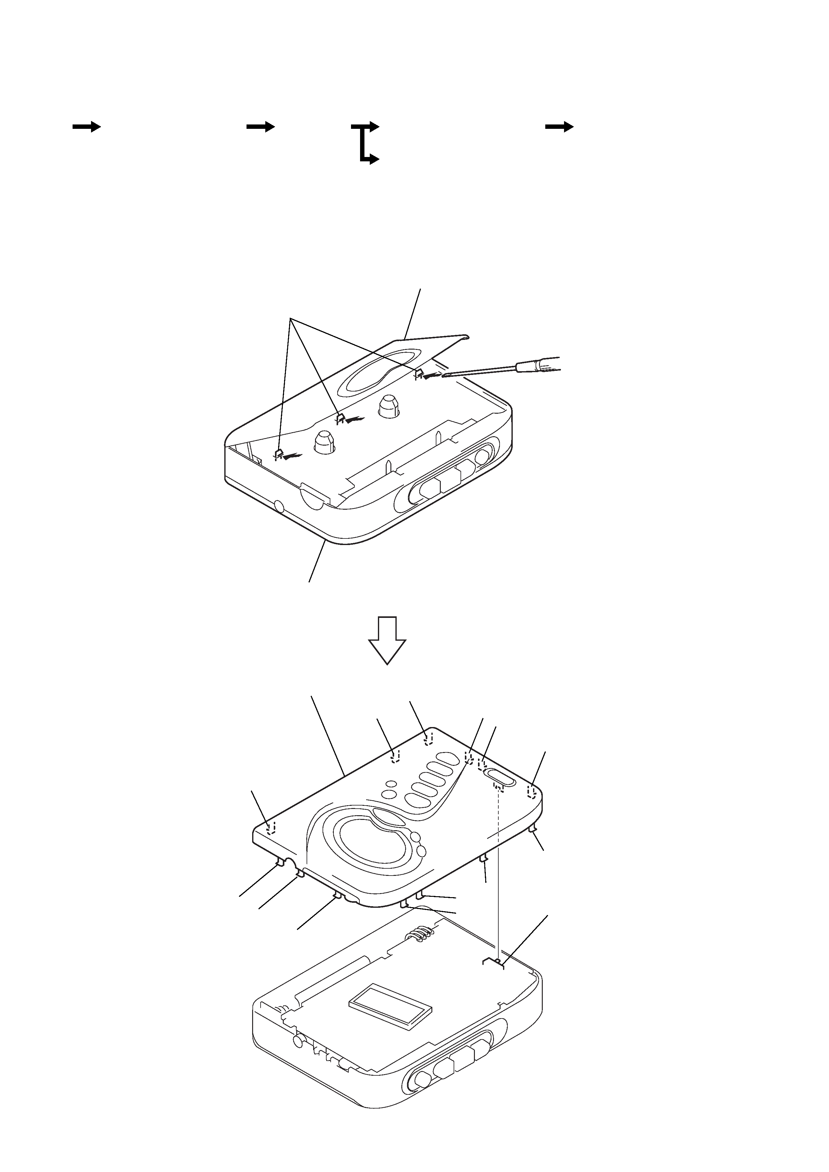
2-2. MAIN BOARD
4 two claws
1 HEAD FLEXIBLE board (CN301)
2 Unsolder the 4 places.
5 MAIN board
3 screw (M1.4), toothed lock (WH)
1 Open the holder (sub) assy, cassette.
4 holder (sub) assy, cassette.
A
B
5 spring (torsion)
2-3. HOLDER (SUB) ASSY, CASSETTE
2 Insert a precision screwdriver
(1.4 mm flat-blade) vertically
into portion A to release the
hinge plate.
3 Portion B to release the
hinge plate.