Ver. 1.3 2005.06
With SUPPLEMENT 1
(9-927-646-81)
With SUPPLEMENT 2
(9-927-646-82)
WM-FX193/FX195
RADIO CASSETTE PLAYER
SPECIFICATIONS
US Model
WM-FX193
Canadian Model
AEP Model
E Model
Chinese Model
WM-FX193/FX195
Model Name Using Similar Mechanism
NEW
Tape Transport Mechanism Type
MF-WMFX195-114
Photo : WM-FX195
· Frequency range
FM: 87.5 - 108 MHz (Italy, Saudi Arabia)
87.6 - 107.9 MHz (Other countries)
AM: 526.5 - 1606.5 kHz (Italy, Saudi Arabia))
531 - 1602 kHz (Other countries)
·Power requirement
3 V DC batteries R6 (AA) x 2
· Dimensions
89.1 x 117.7 x 35.5 mm (w/h/d) incl. projecting parts and
controls
· Mass
Approx. 140 g/Approx. 220 g incl. batteries and a cassette
· Supplied accessories
Stereo headphones or Stereo earphones (1)/Belt clip (1)
Design and specifications are subject to change without notice.
Battery life (approximate hours)
(EIAJ*)
Sony alkaline LR6 (SG)
Sony R6P (SR)
playback
25
7.5
radio
55
18
* Measured value by the standard of EIAJ (Electronic
Industries Association of Japan). (Using a Sony HF series
cassette tape)
Note
· The battery life may shorten depending on the operation of
the unit.
SERVICE MANUAL
Sony Corporation
Personal Audio Group
Published by Sony Engineering Corporation
9-927-646-12
2005F02-1
© 2005.06
2
Specifications ........................................................................... 1
1. GENERAL
Location and Function of Controls .................................... 2
2. DISASSEMBLY
2-1. Cabinet (Rear) Sub ASSY .......................................... 3
2-2. Main Board ................................................................. 3
2-3. Mechanism Deck ........................................................ 4
2-4. Belt, Capstan/Reel Motor (M901) .............................. 4
2-5. Holder Sub ASSY, Cassette ........................................ 5
3. ADJUSTMENTS
3-1. Mechanical Adjustments ............................................. 6
3-2. Electrical Adjustments ................................................ 6
4. DIAGRAMS
4-1. Block Diagram ............................................................ 9
4-2. Printed Wiring Boards ............................................... 11
4-3. Schematic Diagram ................................................... 13
5. EXPLODED VIEWS
5-1. Cabinet Section ......................................................... 17
5-2. Mechanism Section -1 .............................................. 19
5-3. Mechanism Section -2 .............................................. 20
6. ELECTRICAL PARTS LIST ................................... 21
Flexible Circuit Board Repairing
· Keep the temperature of the soldering iron around 270°C during
repairing.
· Do not touch the soldering iron on the same conductor of the
circuit board (within 3 times).
· Be careful not to apply force on the conductor when soldering or
unsoldering.
Notes on chip component replacement
· Never reuse a disconnected chip component.
· Notice that the minus side of a tantalum capacitor may be dam-
aged by heat.
TABLE OF CONTENTS
SECTION 1
GENERAL
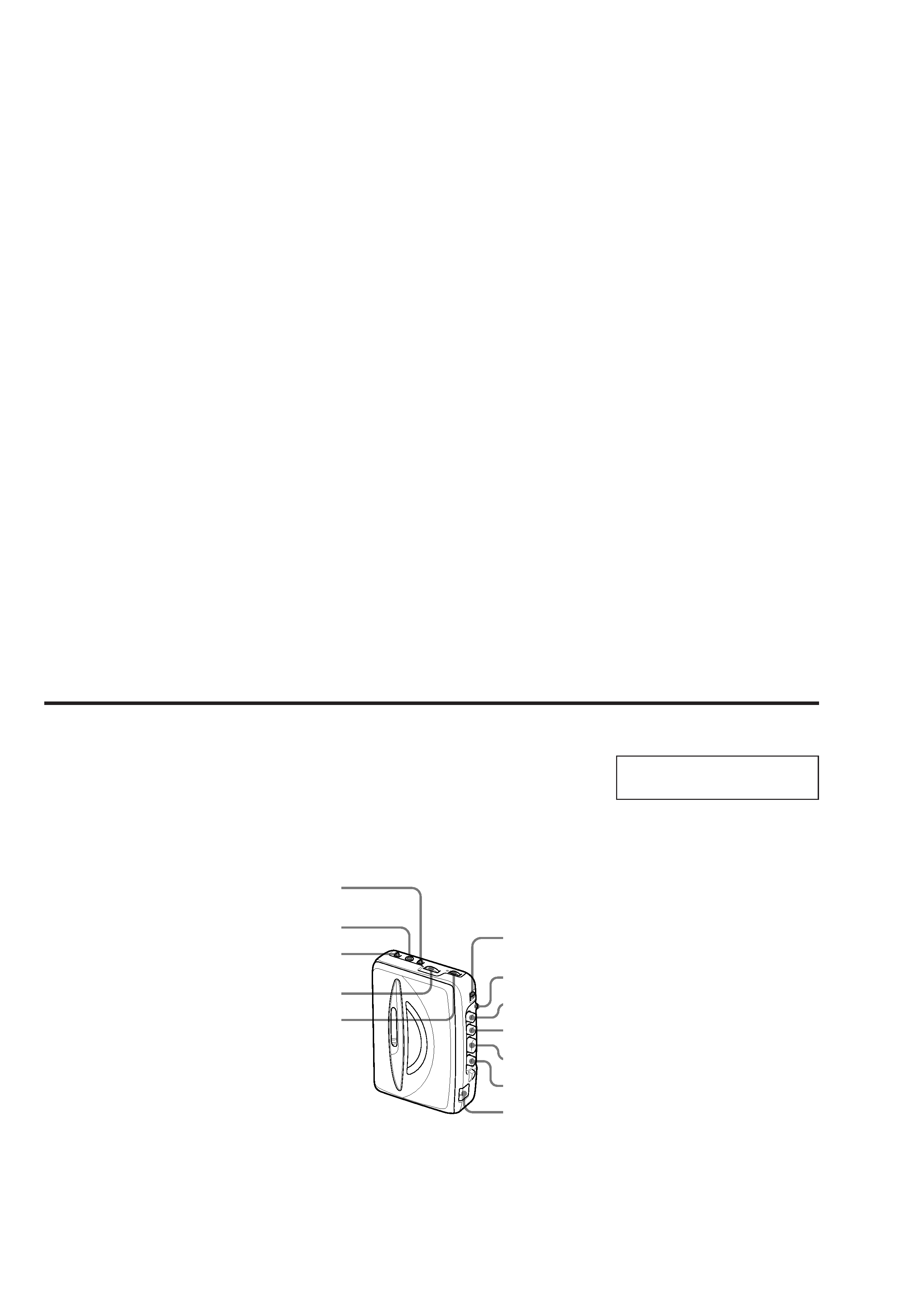
nPLAY
MEGA BASS/
OFF (FX195 only)
M
m
FM/AM/TAPE
(RADIO OFF)
VOLUME
TUNING
FM MODE
i
AVLS NORM/
LIMIT
BATT
x
LOCATION AND FUNCTION OF CONTROLS
This section is extracted from
instruction manual.
3
SECTION 2
DISASSEMBLY
Note : Follow the disassembly procedure in the numerical order given.
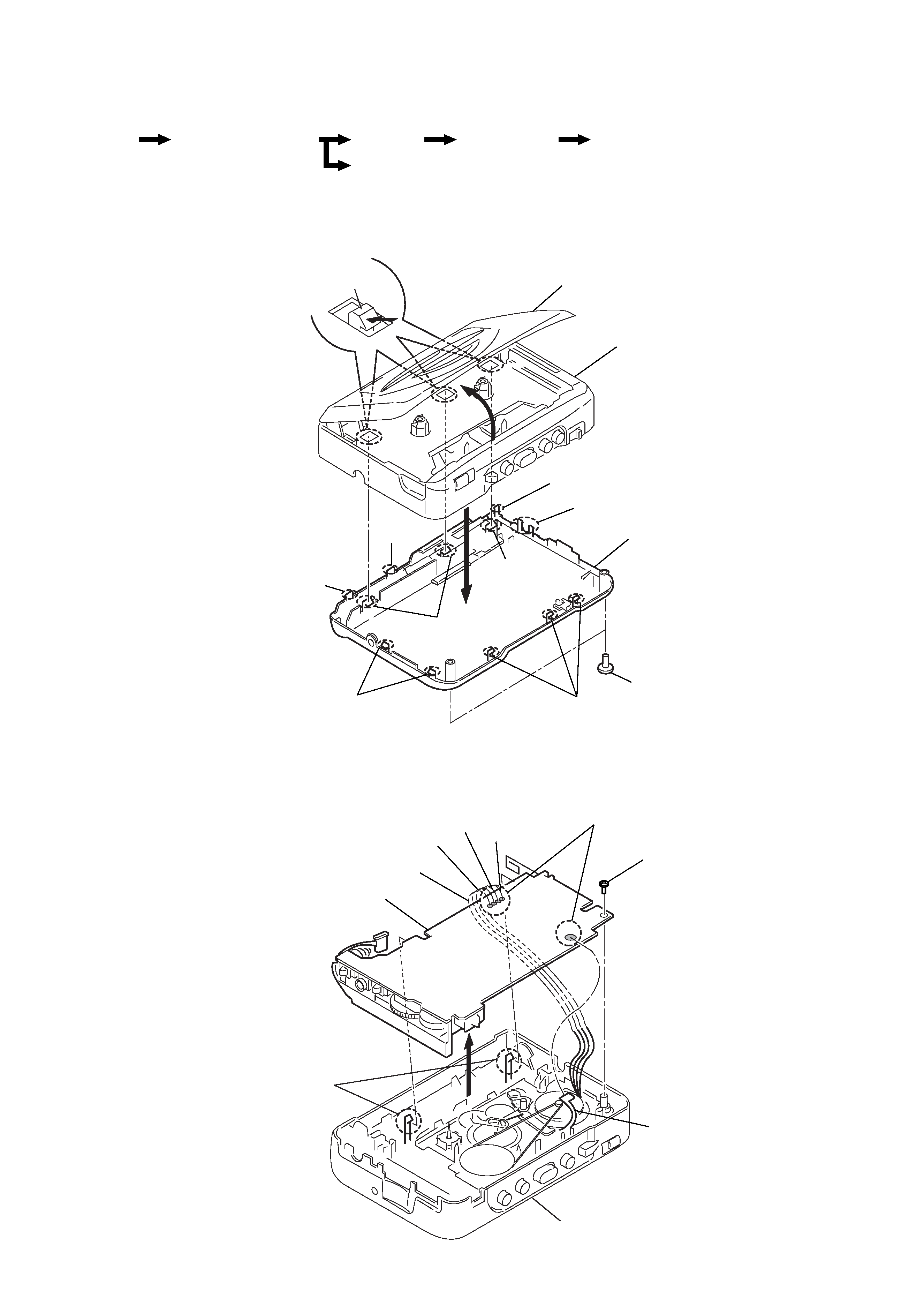
2-1. CABINET (REAR) SUB ASSY
2-2. MAIN BOARD
z
The equipment can be removed using the following procedure.
Main board
Cabinet (rear) sub ASSY
Holder sub ASSY, Cassette
Mechanism deck
Belt, Capstan/reel moter (M901)
Set
1
Screws B1.7x9
3
Claws
4
2
6
Claws
Holder sub ASSY, Cassette
Cabinet (front)
Cabinet (rear) sub ASSY
3
Claws
3
Claws
5
Claw
4
Claws
4
Claw
5
Claw
5
Claw
1
Screw WH1.4
3
Claws
2
Remove solder
4
Head flexible board
Red
White
Orange
Black
Cabinet (front)
Main board
4
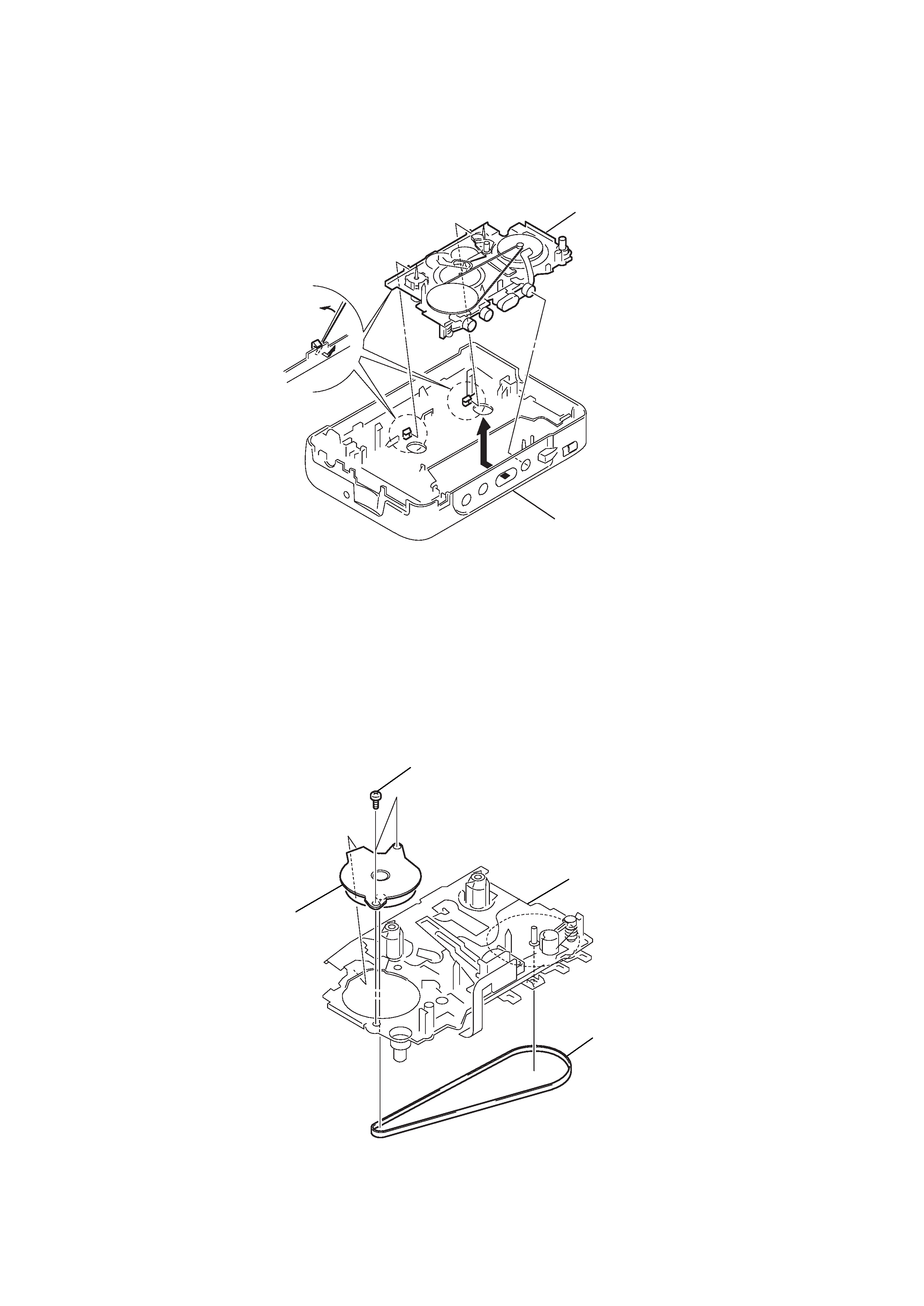
2-3. MECHANISM DECK
2-4. BELT, CAPSTAN/REEL MOTOR (M901)
2
Mechanism deck
1
Insert the precision screwdriver
(1.4 mm flat-blabe) in to the slit
and release two claws.
Cabinet (front)
Mechanism deck
2
Screws (M1.4)
3
Capstan/reel motor (M901)
1
Belt
5
3
Move it away from projection
1
5
Holder sub ASSY, Cassette
Holder sub ASSY, Cassette
Holder sub ASSY, Cassette
Cabinet (front)
Cabinet (front)
Cabinet (front)
2
Move it away
from projection
4
Spring (torsion)
Holder sub ASSY, Cassette
Cabinet (front)
5
4
1
3
2
Spring (torsion)
Hinge
Hinge
Dial indicator
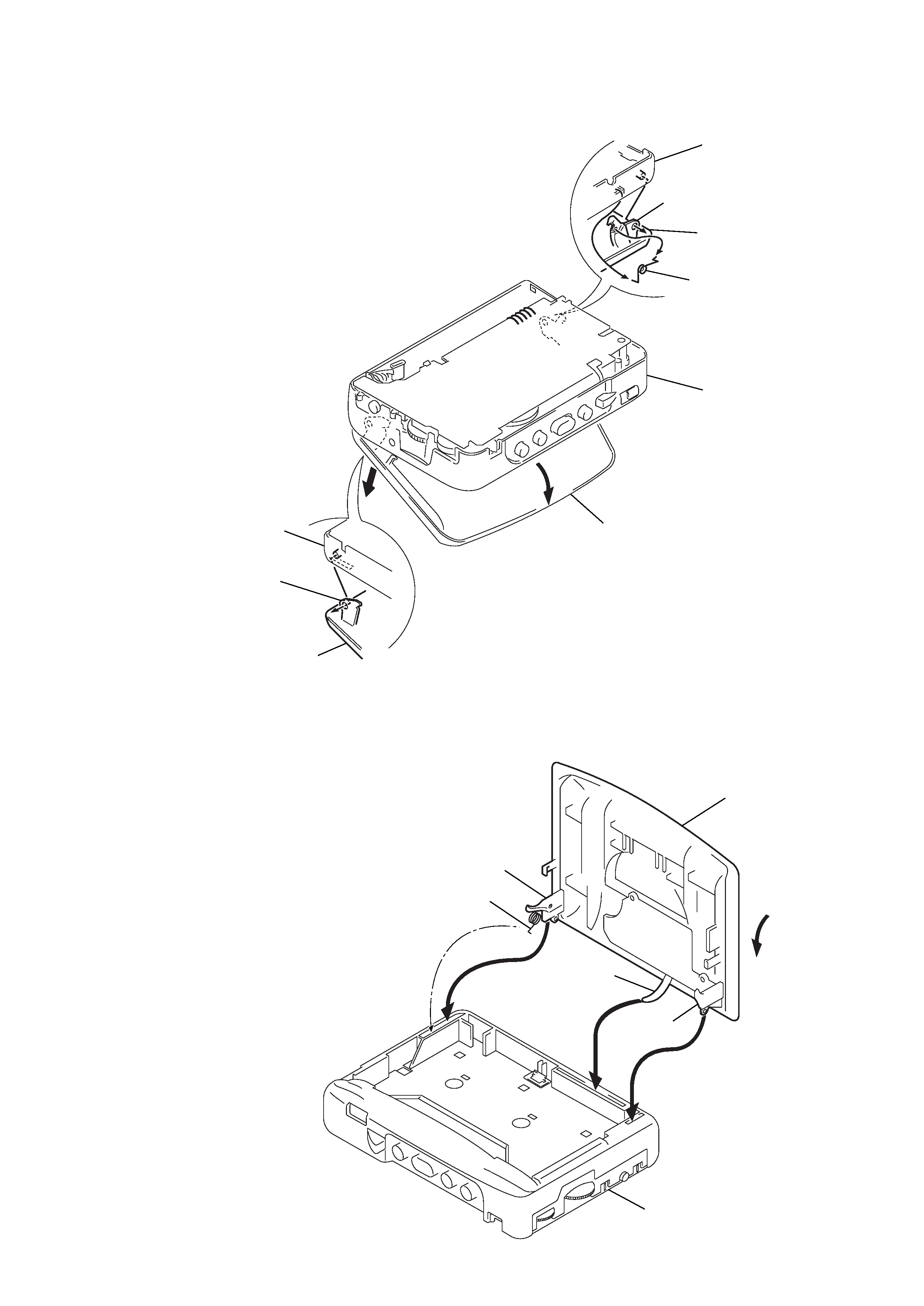
2-5. HOLDER SUB ASSY, CASSETTE
z
CAUTIONS DURING ASSEMBLY
1 Insert the dial indicator to the square hole of the cabinet
(front) and align to the pointer.
2 Insert the spring (torsion) in to the L shape slot as shown in
the figure.
3, 4 Insert the hinge of the "Holder sub ASSY, Cassette".
5 Close the "Holder sub ASSY, Cassette" then press in.