WM-FX141
US Model
AEP Model
E Model
SERVICE MANUAL
RADIO CASSETTE PLAYER
MICROFILM
Model Name Using Similar Mechanism
WM-FX101
Tape Transport Mechanism Type
MF-WMFX103-48
SPECIFICATIONS
Radio Frequency
FM : 87.6 108 MHz (US, Chilean, Latin America, Central and
South America Models)
: 65.0 107.9MHz (East European Model)
: 87.6 107.9 MHz (Other Models)
AM : 530 1,710 kHz (US, Chilean, Latin America, Central and
South America Models)
: 531 1,602kHz (Other Models)
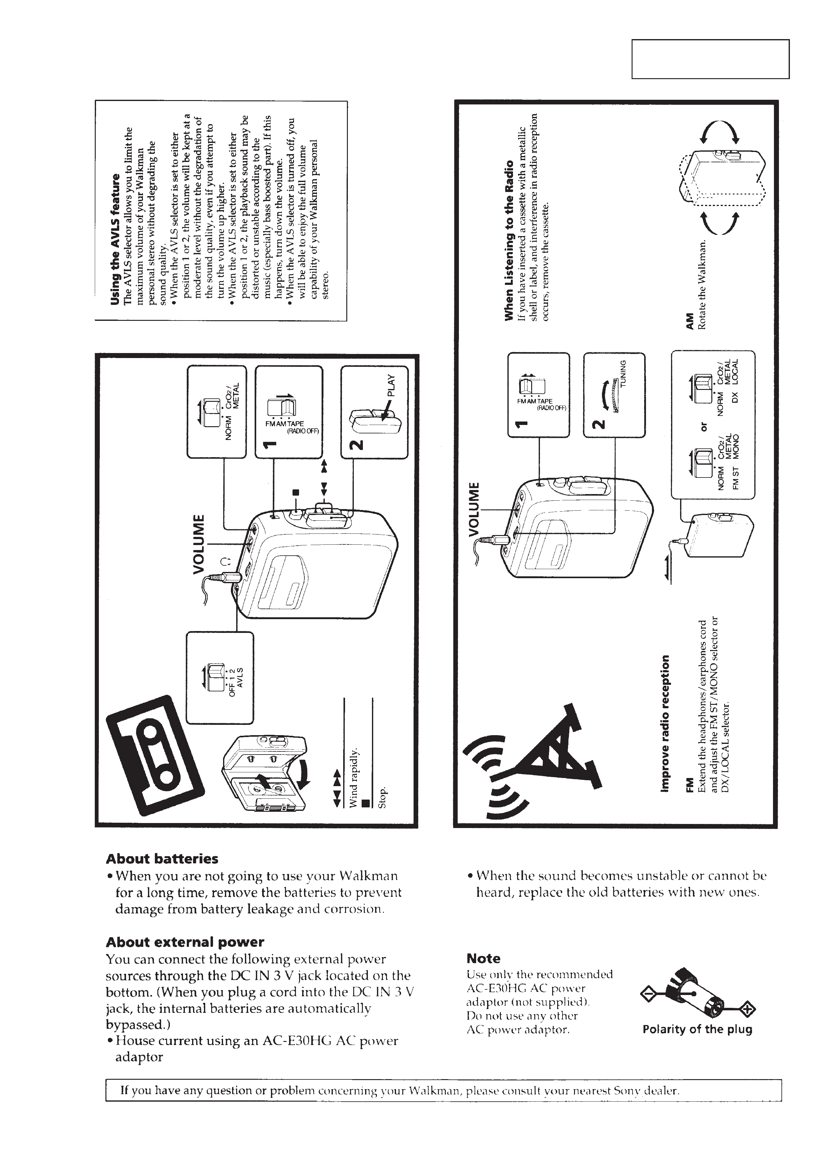
Power requirements
3V DC batteries R6 (size AA)
× 2
External DC 3V power sources
Battery life
(Aprroximate hours)
Battery
Playback
Radio
Sony alkaline LR6 (SG)
16 hrs
48 hrs
Sony R6P (SR)
4.5 hrs
16 hrs
Dimensions
93.9
× 118.5 × 35.9 mm (w/h/d)
(33/4
× 43/4 × 13/16 in.) incl. projecting parts
Mass
205g (7.3 oz) incl.batteries
Supplied accessories
· Stereo headphones or earphones (1)
· Belt clip (1)
Design and specifications are subject to change without notice.
Ver 1.3 1999. 05
With SUPPLEMENT-1 (9-923-296-81)
With SUPPLEMENT-2 (9-923-296-82)

-- 2 --
TABLE OF CONTENTS
1. GENERAL ·········································································· 3
2. DISASSEMBLY
2-1. Cabinet (Rear) ································································· 4
2-2. Mechanism Deck and Main Board ································· 4
2-3. Main Board ····································································· 5
2-4. Cassette Lid ····································································· 5
2-5. Dial Pointer Setting ························································· 5
3. ADJUSTMENT
3-1. Mechanical Adjustment ·················································· 6
3-2. Electrical Adjustment ······················································ 6
4. DIAGRAMS
4-1. Block Diagram ································································ 9
4-2. Schematic Diagram ······················································· 11
4-3. Printed Wiring Board ···················································· 13
4-4. IC Block Diagram ························································· 17
5. EXPLODED VIEWS
5-1. Cabinet and Board Section ··········································· 18
5-2. Mechanism Section (MF-WMFX103-48) ···················· 19
6. ELECTRICAL PARTS LIST ······································· 20
Notes on chip component replacement
· Never reuse a disconnected chip component.
· Notice that the minus side of a tantalum capacitor may be
damaged by heat.
Flexible Circuit Board Repairing
· Keep the temperature of soldering iron around 270°C
during repairing.
· Do not touch the soldering iron on the same conductor of the
circuit board (within 3 times).
· Be careful not to apply force on the conductor when soldering
or unsoldering.
-- 3 --
SECTION 1
GENERAL
This section is extracted
from instruction manual.
-- 4 --
SECTION 2
DISASSEMBLY
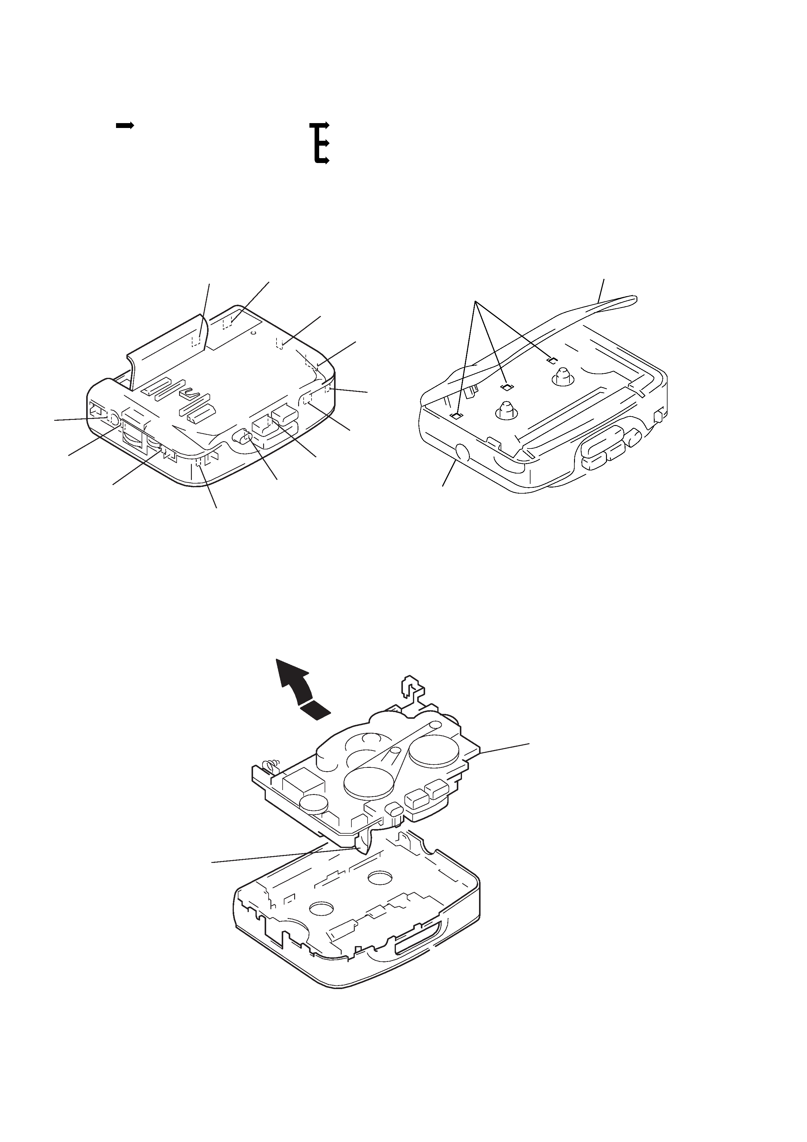
2-1.
CABINET (REAR)
2-2.
MECHANISM DECK AND MAIN BOARD
1 Remove the mechanism deck
and main board in the
direction of the arrow.
head flexible board
mechanism deck
and MAIN board
* note for installation :
Make sure to put the head flexible
board to ditch before install the
mechanism deck and MAIN board.
Note :
Follow the disassembly procedure in the numerical order given.
Note :
Disassemble the unit in the order as shown below.
Cabinet (Rear)
Mechanism deck and main board
Main board
Cassette lid
Dial pointer setting
Cassette lid
Cabinet(rear)
1 Open the cassette lid and release claw A.
2 Remove the cabinet(rear).(Release
all claws B from M in alphabetical order.)
A
B
C
D
E
I
K
M
L
J
H
G
F
-- 5 --
2-3.
MAIN BOARD
1 head flexible board
3 MAIN board
2 claws
2-4.
CASSETTE LID
Front cabinet
A
3 Cassette lid
(Remove it in the
direction of the arrow)
1 Release the catch A.
2 Release the catch B.
B
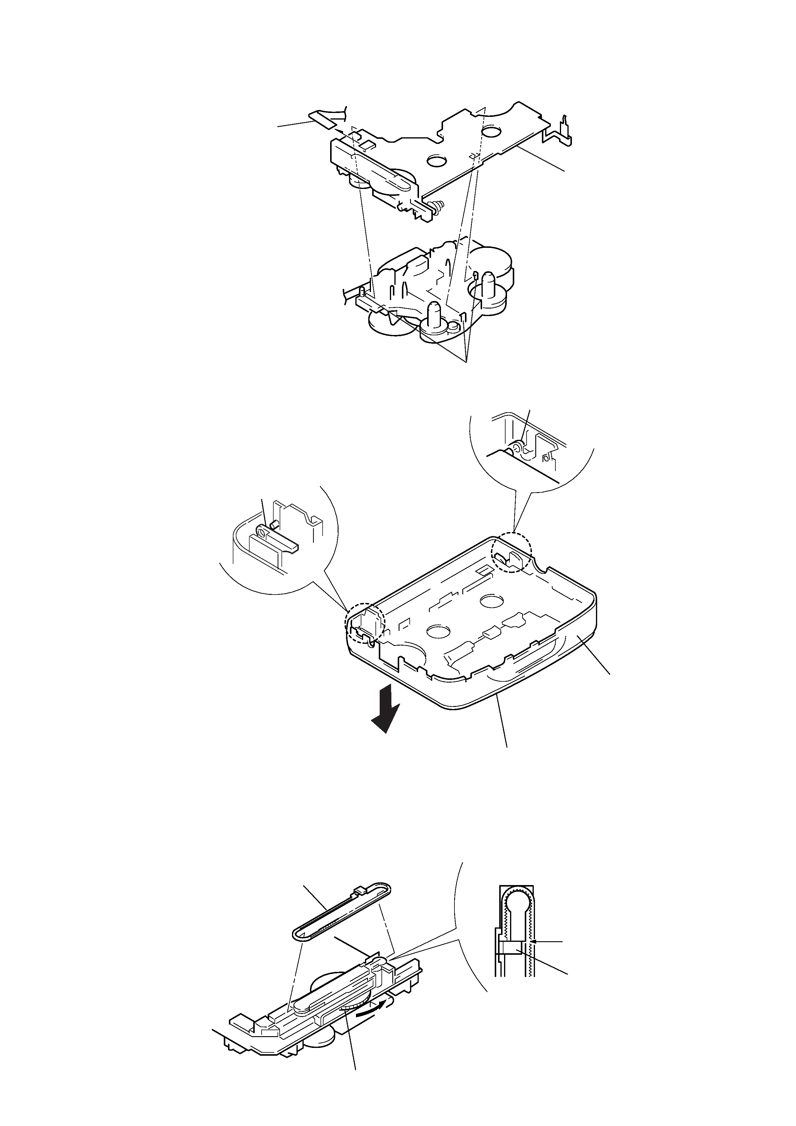
2 Align pointer with arrow
marked side as shown in Fig.1
and then fit to groove in the
order of A and B.
Align
Pointer
Fig. 1
Pointer
1 Rotate tune knob fully to arrow direction.
A
B
2-5.
DIAL POINTER SETTING