WM-FS111
US Model
Canadian Model
AEP Model
E Model
SERVICE MANUAL
RADIO CASSETTE PLAYER
MICROFILM
SPECIFICATIONS
Model Name Using Similar Mechanism
NEW
Tape Transport Mechanism Type
MF-WMFS111-114
Radio Frequency
FM : 87.6 108 MHz
(North, Central and South America)
87.5 108 MHz (Italy and Saudi Arabia)
65 107.9 MHz (Eastern Europe)
87.6 107.9 MHz (Other countries)
AM : 530 1,710 kHz
(North, Central and South America)
526.5 1,606.5 kHz (Italy and Saudi Arabia)
531 1,602 kHz (Other countries)
Power Requirements
3 V DC Batteries R6 (AA)
× 2
Dimensions
104.0
× 122.0 × 48.7 mm(4 1/
8
× 4 7/
8
× 1 15/
16
inches)
(w/h/d) incl. projecting parts and controls
Mass
Approx. 300 g (10.6 oz)
Approx. 380 g (13.5 oz) incl. batteries and a cassette
Supplied Accessories
· Stereo headphones or stereo earphones (1)
· Belt clip (1)
Design and specifications are subject to change without notice.
Ver 1.0 1999. 03
-- 2 --
TABLE OF CONTENTS
Notes on chip component replacement
· Never reuse a disconnected chip component.
· Notice that the minus side of a tantalum capacitor may be
damaged by heat.
Flexible Circuit Board Repairing
· Keep the temperature of soldering iron around 270°C
during repairing.
· Do not touch the soldering iron on the same conductor of the
circuit board (within 3 times).
· Be careful not to apply force on the conductor when soldering
or unsoldering.
SECTION 1
GENERAL
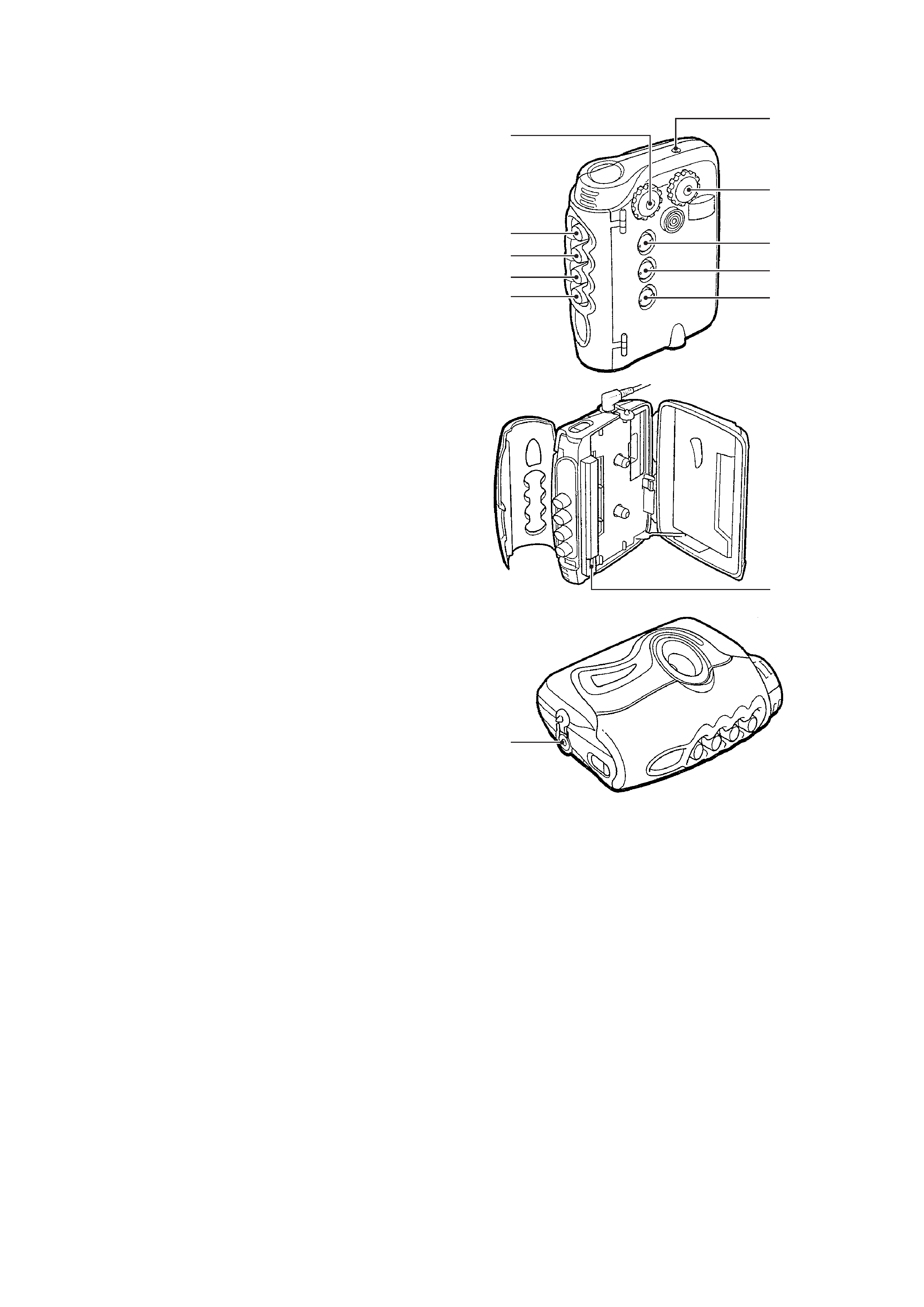
1
VOL (volume) knob
2
BATT (battery) lamp
3
TUNING knob
4
FUNCTION selector
5
AVLS selector
6
MEGA BASS selector
7
) REW button
8
( PLAY button
9
0 FF button
0
p STOP button
!¡
TAPE/FM MODE switch (AEP, E Model)
TAPE/FM SENS switch (US, CND, MX Model)
!TM
2 jack
· Abbreviation
CND : Canadian model
MX
: Mexican model
1. GENERAL ·········································································· 2
2. SERVICE NOTE
2-1.
How to Install The Wire Assembly ····································· 3
2-2.
Water Proof Section ···························································· 3
3. DISASSEMBLY
3-1.
Holder Cassette Sub Assembly and Dial Scale ·················· 4
3-2.
Main Assembly ··································································· 5
3-3.
Main Board ········································································· 6
3-4.
Mechanism Deck ································································ 6
3-5.
Belt ····················································································· 7
3-6.
Magnetic head ···································································· 7
4. MECHANICAL ADJUSTMENT ·································· 8
5. ELECTRICAL ADJUSTMENT ···································· 8
6. DIAGRAMS
6-1.
Block Diagram ································································· 11
6-2.
Printed Wiring Board ························································ 13
6-3.
Schematic Diagram ·························································· 15
6-4.
IC Block Diagrams ··························································· 17
7. EXPLODED VIEWS ················································· 18
8. ELECTRICAL PARTS LIST ··································· 23
1
0
9
8
7
2
3
4
5
6
!¡
!TM
-- 3 --
SECTION 2
SERVICE NOTE
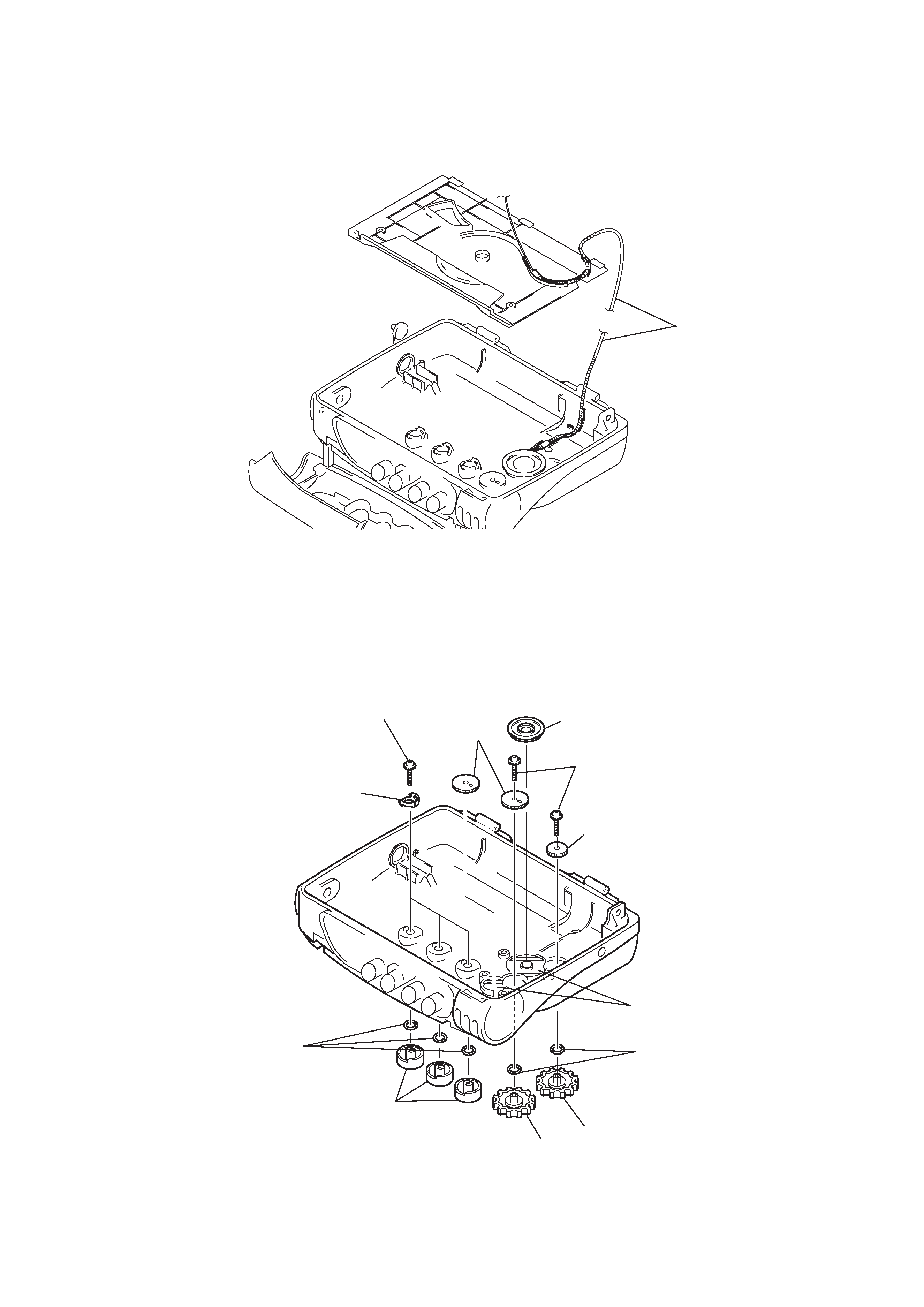
2-1. HOW TO INSTALL THE WIRE ASSEMBLY
· To install the wire assembly, route the wire assembly in the correct position referring to the illustration below.
2-2. WATER PROOF SECTION
NOTE : In case the parts in the figure are removed for repair, treat them to protect from water drop following the instructions in the figure
(spread grease, bond etc.)
· sony grease SGL-601 : 7-651-000-10
Wire assembly
Knob (function)
Knob (VOL)
Knob (TUNE)
Tapping screw (B)(1.4x6)
Tapping screw (B)(1.4x6)
Joint (AVLS)
Gear (VOL)
Gear (B)
Gear (A)
O ring (DIA. 2.5xDIA. 4.5)
(Apply Sony grease SGL-601)
O ring
(Apply Sony grease SGL-601)
Apply Sony grease SGL-601
-- 4 --
SECTION 3
DISASSEMBLY
Note : Follow the disassembly procedure in the numerical order given.
Note : Disassemble the unit in the order as shown below.
Set
Holder cassette sub assembly and dial scale
Main assembly
Main board
Mechanism deck
Magnetic head
Belt
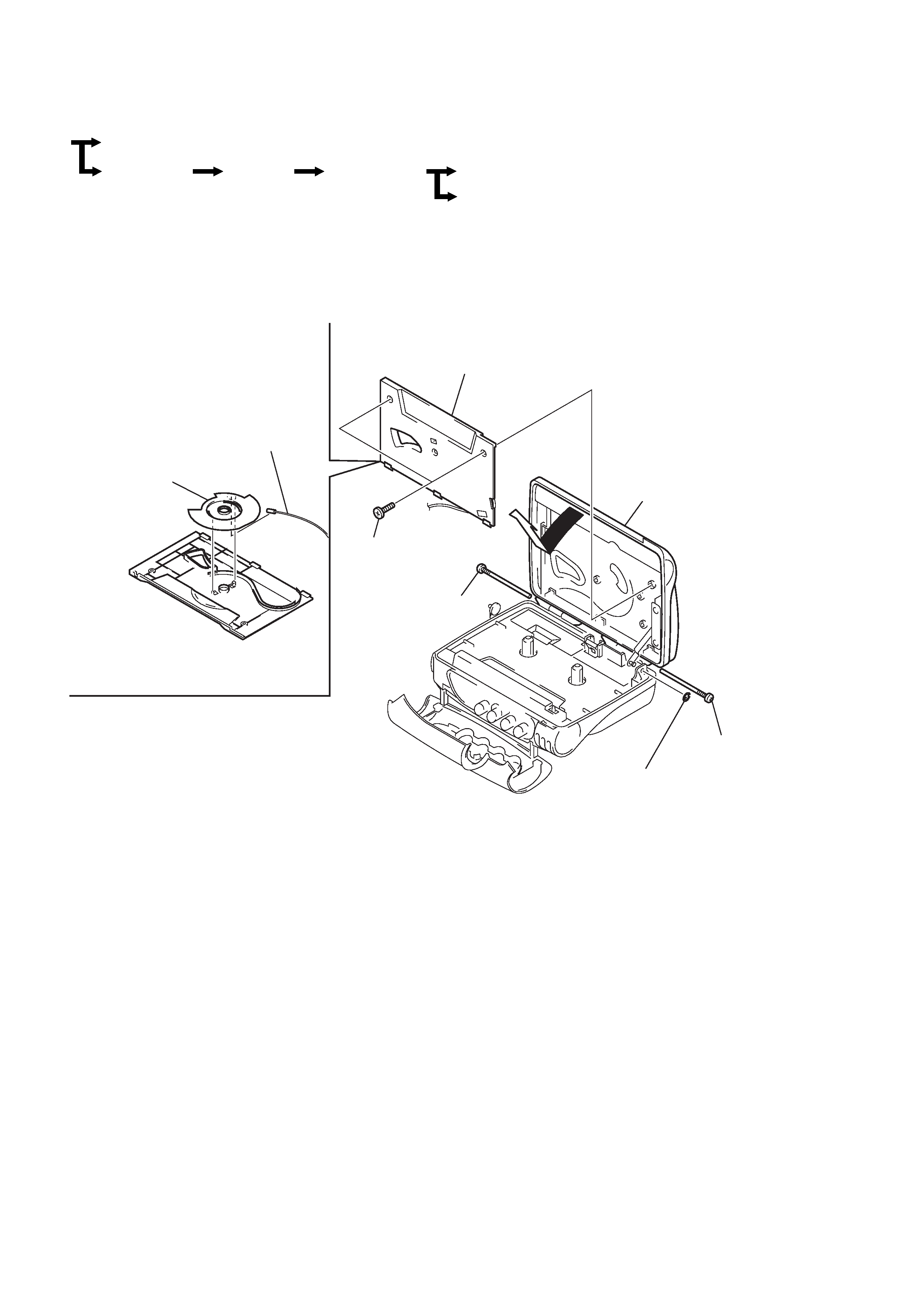
3-1. HOLDER CASSETTE SUB ASSEMBLY AND DIAL SCALE
1 Stop ring (E-1.2)
2 Tapping screw
3 Tapping screw
4 Holder cassette sub assembly
6 Cover (Cassette)
7 Dial scale
8 Wire assembly
5 Two tapping screws
(B1.7
× 4)
-- 5 --
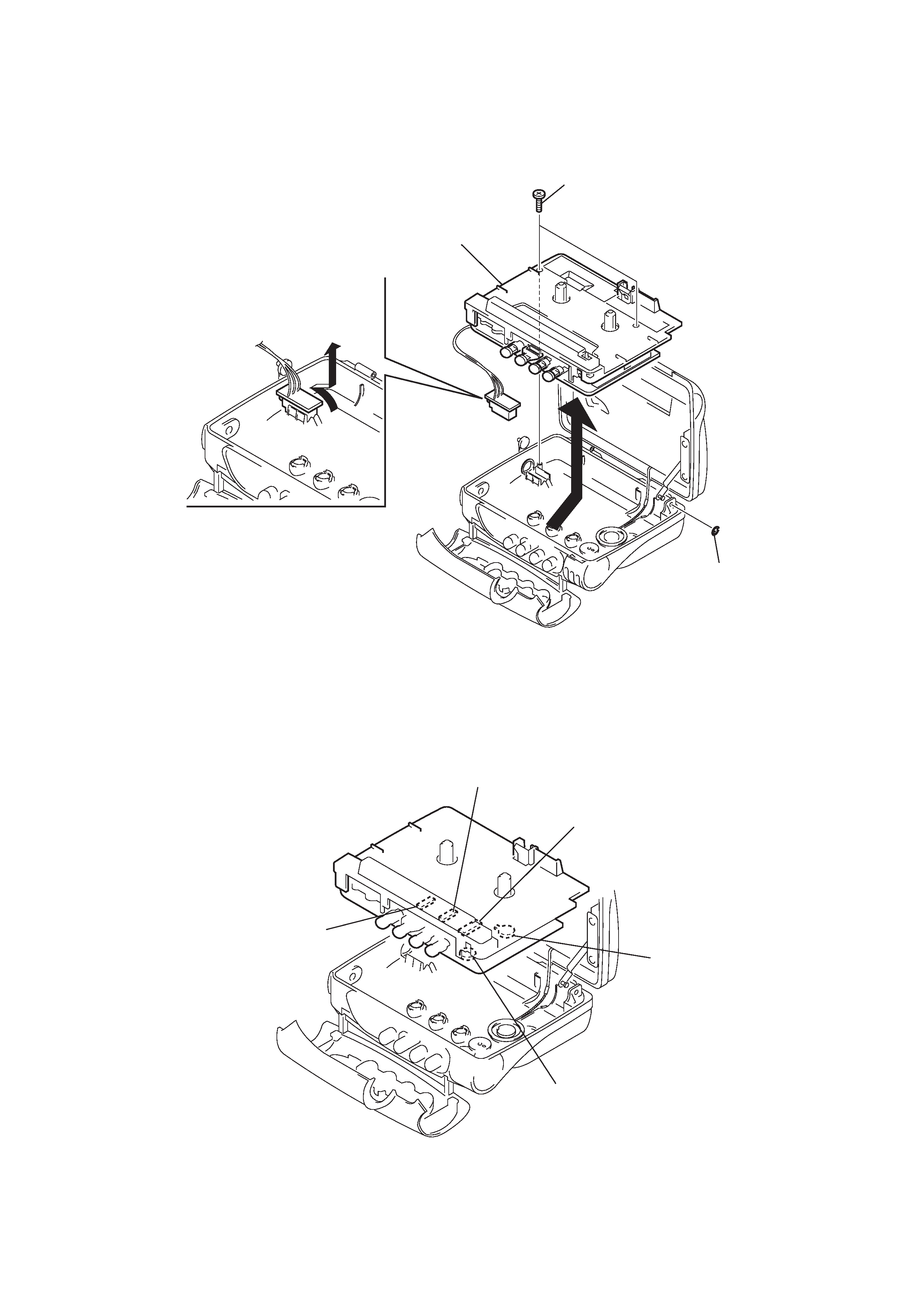
3-2. MAIN ASSEMBLY
3 Remve the main assembly in the direction
of arrow.
(Be careful not to focibly pull the wire that connects
the main board and the headphone board.)
4 Remove the headphone
borad in the direction of arrow.
1 Stop ring (E 1.2)
2 Two screws (+B1.7
× 7)
CAUTION WHEN ASSEMBLING THE MAIN ASSEMBLY
· Assemble the main assembly in a way that each switch mates with the corresponding knob each other.
Function switch (S301)
Tuner (CV1)
AVLS switch (S305)
Mega Bass switch
(S306)
Volume (RV301)