MICROFILM
SERVICE MANUAL
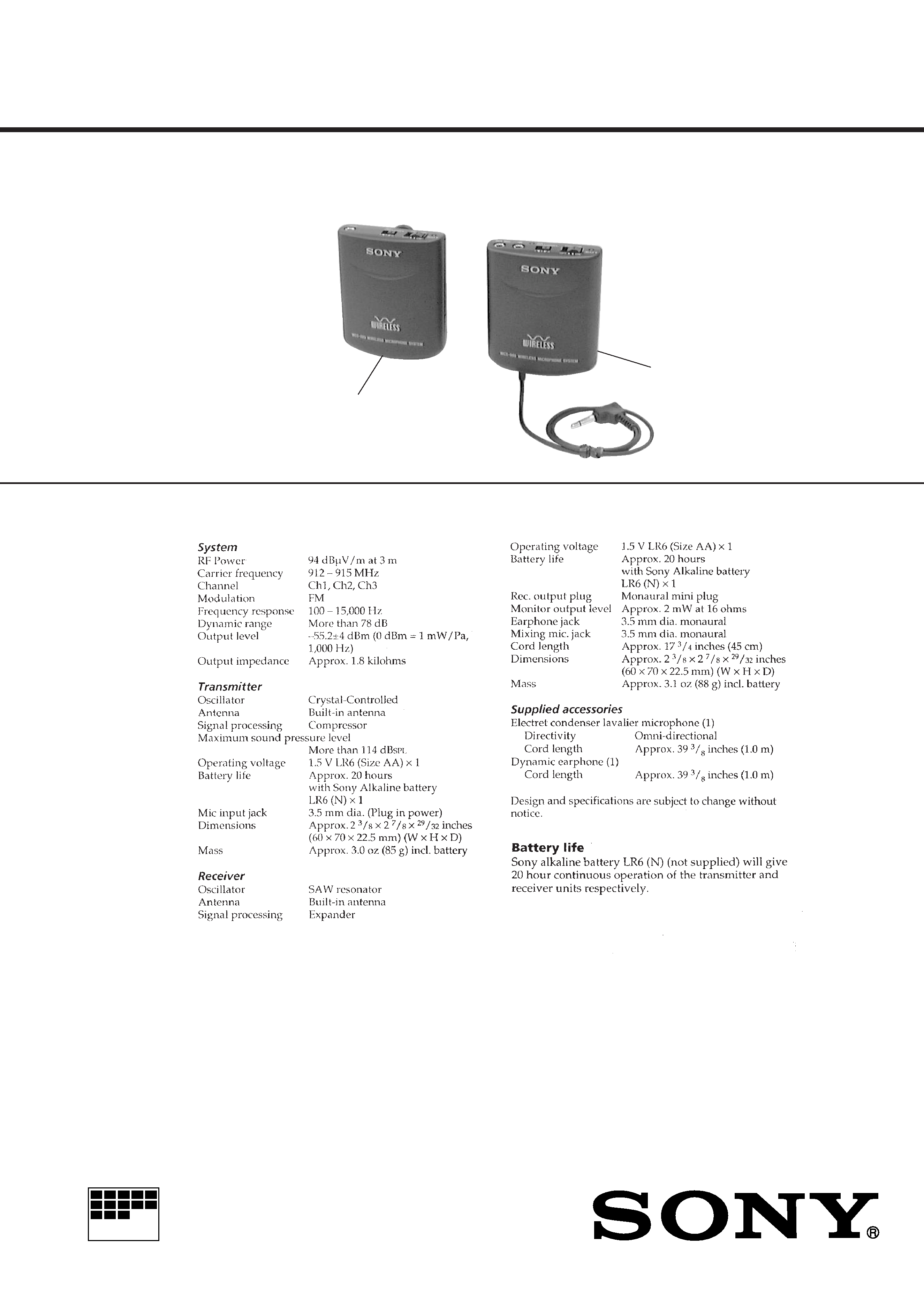
WIRELESS MICROPHONE SYSTEM
US Model
Canadian Model
SPECIFICATIONS
WCS-999
Transmitter
Receiver
Ver 1.0 1999. 09

2
TABLE OF CONTENTS
1.
GENERAL ............................................................ 3
2.
DISASSEMBLY ......................................................... 4
3.
ELECTRICAL ADJUSTMENTS
TX Section ......................................................................
6
RX Section ......................................................................
8
4.
DIAGRAMS
4-1. Block Diagram TX Section .....................................
9
4-2. Block Diagram RX Section ..................................... 11
4-3. Printed Wiring Boards TX Section .......................... 13
4-4. Schematic Diagram TX Section ............................... 15
4-5. Printed Wiring Boards RX Section ......................... 17
4-6. Schematic Diagram RX Section .............................. 19
5.
EXPLODED VIEWS ................................................ 23
6.
ELECTRICAL PARTS LIST ............................... 25
Notes on chip component replacement
· Never reuse a disconnected chip component.
· Notice that the minus side of a tantalum capacitor may be dam-
aged by heat.
3
SECTION 1
GENERAL
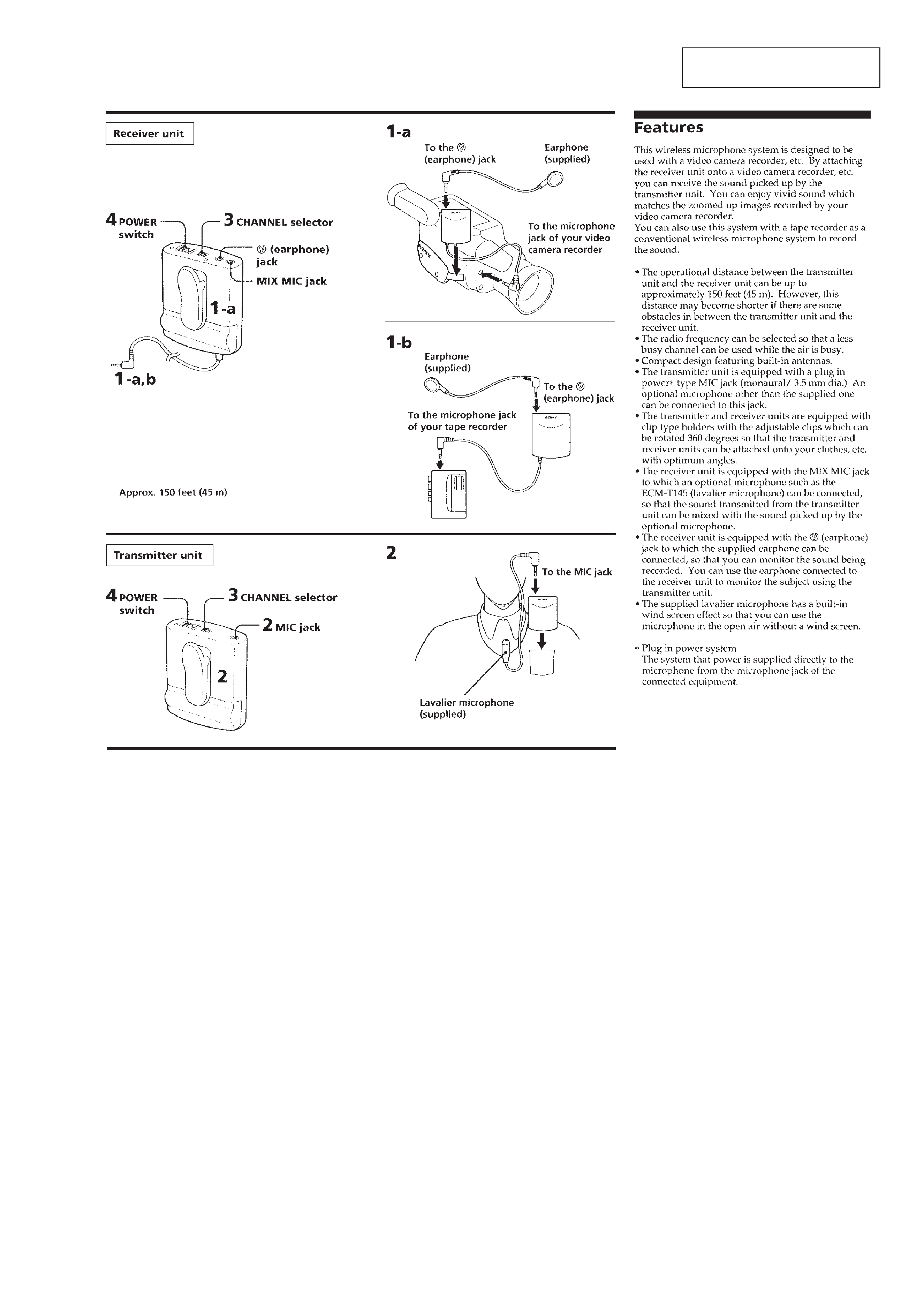
This section is extracted from
instruction manual.
4
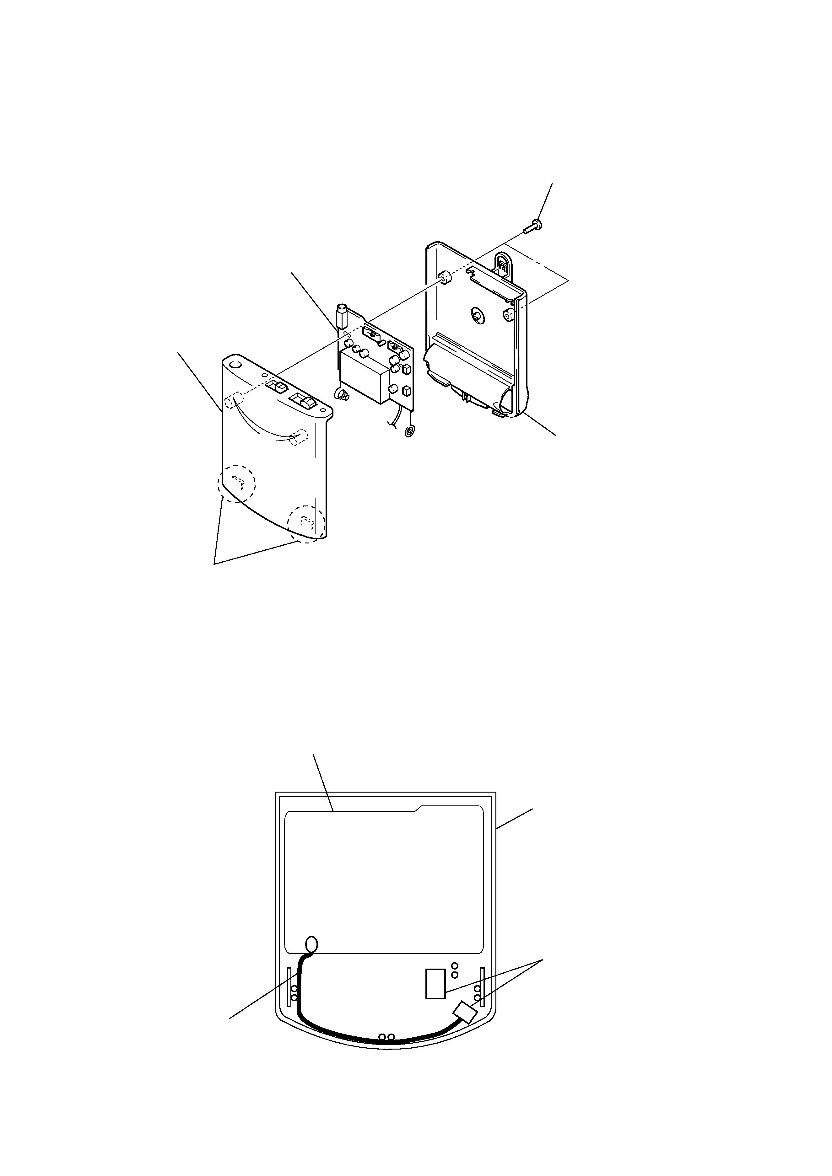
TX BOARD
ANTENNA SETTING
Note: Follow the disassembly procedure in the numerical order given.
SECTION 2
DISASSEMBLY
1
two screws
(P2
× 6)
4
TX board
3
case (upper)
2
two claws
3
case (lower)
TX board
case (upper)
antenna
case (upper) rear view
cushion (lower), switch
5
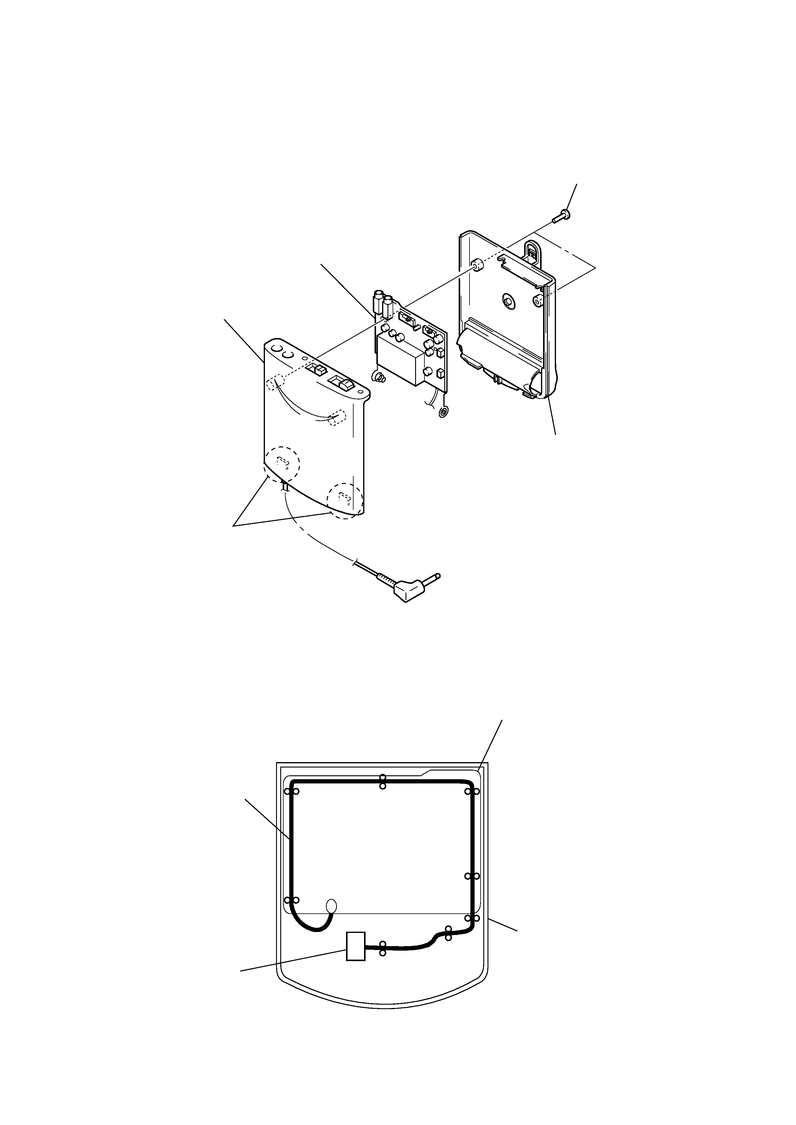
RX BOARD
ANTENNA SETTING
3
case (upper)
2
two claws
3
case (lower)
1
two screws (P2
× 6)
4
RX board
antenna
case (upper)
case (upper) rear view
RX board
cushion (lower), switch