- 1 -
Service Manual
SERVICEMANUAL
SERVICEMANUAL
SERVICEMANUAL
SERVICEMANUAL
SERVICEMANUAL
DIGITAL RECEIVER
MagellanII
MagellanII
MagellanII
MagellanII
MagellanIICHASSIS
CHASSIS
CHASSIS
CHASSIS
CHASSIS
MODEL
COMMANDER
DEST
VTX-D800U
VTX-D800U
VTX-D800U
VTX-D800U
VTX-D800U
RM-X800
UK
VTX-D800N
VTX-D800N
VTX-D800N
VTX-D800N
VTX-D800N
RM-X800
FINLAND/SWEDEN
VTX-D800E
VTX-D800E
VTX-D800E
VTX-D800E
VTX-D800E
RM-X800
ESP

- 2 -
Service Manual
TABLE OF CONTENTS
Safety Warning.
....................
3
Tools Required.
....................
3
1
Dissassembly
....................
4
1.1
Cover Removal.
....................
4
1.2
Front Panel Removal.
....................
4
1.3
B Board Removal.
....................
5
1.4
Chassis Removal.
....................
5
2
Service Mode [TT Mode]
....................
6
2.1
Special Key Sequence
....................
6
2.2
Special Remote Commander Data Code
....................
6
2.3
Exiting TT Mode
....................
6
3
Entering the TT Command Number
....................
7
3.1
Cancelling a Command Entry
....................
7
3.2
Example
....................
7
4
List of TT Commands
....................
8
5
Power Supply
....................
11
5.1
Power Supply Detailed Description
....................
12
6
Technical Specifications
.
....................
1
5
7
Device descriptions.
....................
19
8
Diagrams
8.1
Block Diagram.
....................
21
8.2
B board PWB layout.
....................
22
8.3
B board circuit diagram.
8.3.1 Multimedia Processor & Clock Generator ....................
23
8.3.2 Front Panel & Reset
....................
24
8.3.3 Power Supply
....................
25
8.3.4 Audio DAC & Smartlink Switch
....................
26
8.3.5 AV Switch & SCART
....................
27
8.3.6 Tuner NIM
....................
28
9
Exploded View
.
....................
29
10
Electrical Parts List.
....................
30
- 3 -
Service Manual
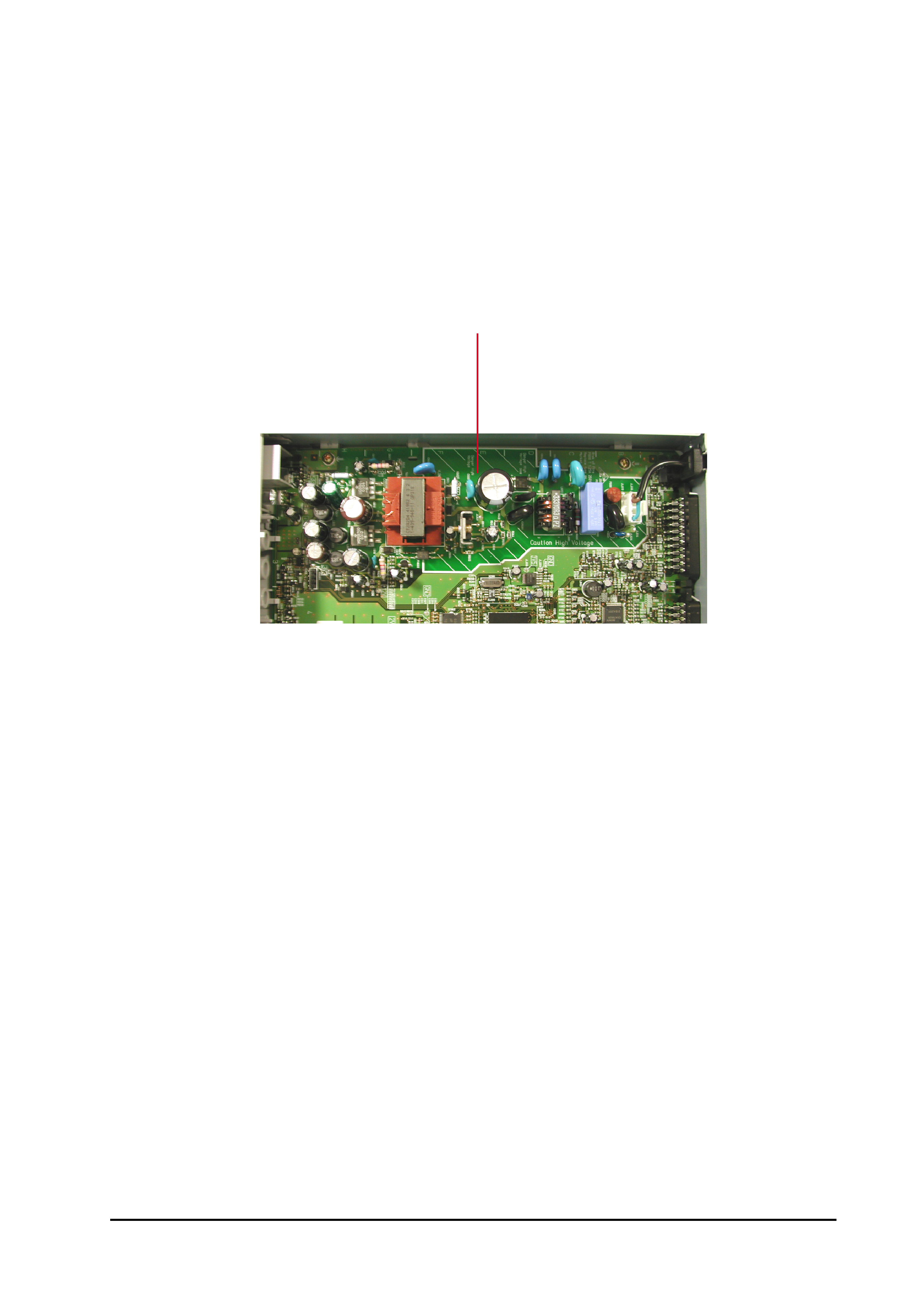
Dangerously high voltages exist on the Power Supply Unit (PSU) PWB (See Fig 1).
FOR THIS REASON,THE RECEIVER MUST ALWAYS BE DISCONNECTED FROM THE MAINS SUPPLY
BEFORE ANY WORK DETAILED IN THIS MANUAL IS CARRIED OUT.
CAUTION !!!
Anti-static precautions should be taken when handling the PWB. Once removed from its fixings, the PWB can
become flexible. Care should be taken to avoid damage to the PWB or components.
All fixings must be replaced correctly for correct performance and continued safety compliance.
Tools Required
Safety Warning
Caution High Voltage
Fig. 1
Philips Screwdriver
- 4 -
Service Manual
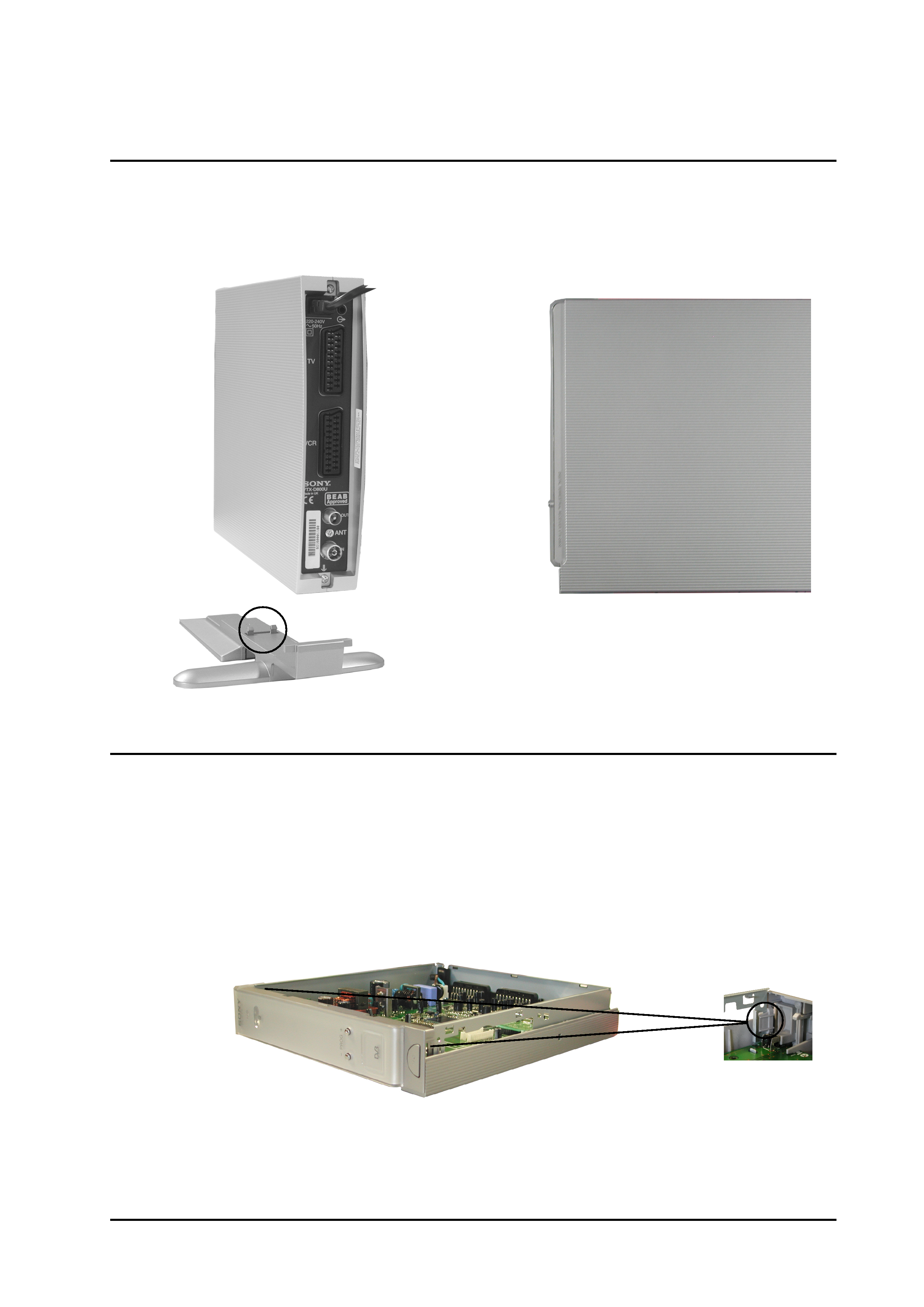
Remove the foot by releasing the clips circled and easing the foot carefully away from the unit. Remove the 2
screws located at the rear of the unit (shown arrowed). Lift the front of the cover slightly and slide towards the rear
of the unit until it is clear. Reassembly is the reversal of removal.
1.1 Cover Removal
1.2 Front Panel Removal
Remove the cover as indicated above. Carefully unhook the front panel locating clips from the chassis, pull the
front panel gently forward and lift clear.
Clip located
on both sides
of Front panel
Lift cover
gently at this
point.
1 Dissassembly
==>
==>
==>
- 5 -
Service Manual
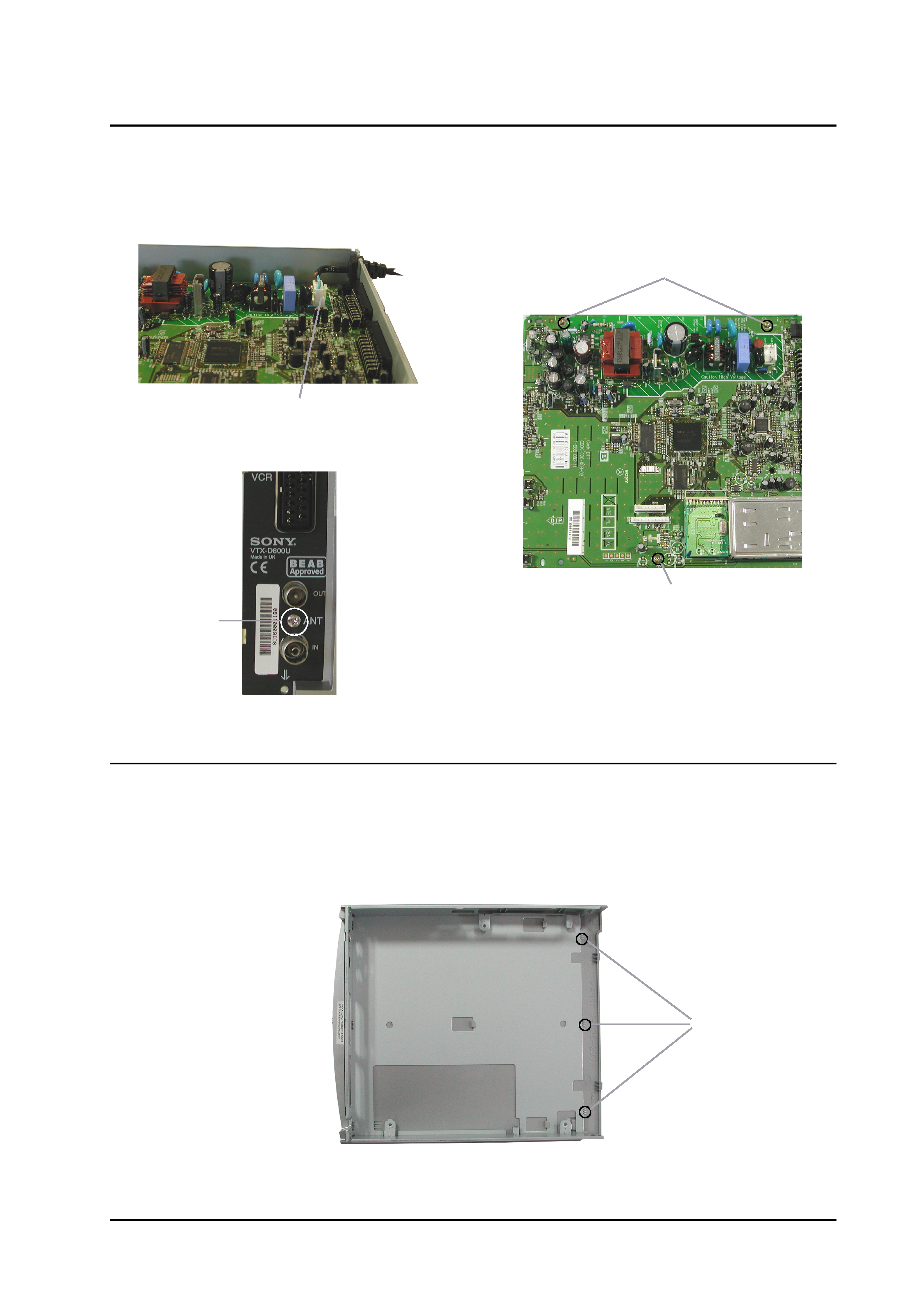
Remove the cover and front panel as indicated in [1-
1] and [1-2]. Disconnect CN600 power cord and remove from
unit. Remove the 1 Philips screw from the rear panel. Remove the 3 Philips screws from the circuit booard. The B
board can then be lifted clear of the chassis.
[ 1.3 ] B Board Removal
==>
==>
==>
==>
CN600
Screw
Screw
Screws
To remove, lift the front of the chassis slightly to clear the stops and slide forward out of the bottom cover.
[ 1.4 ] Chassis Removal
Stops