1
VPF-A1
US Model
Canadian Model
AEP Model
SERVICE MANUAL
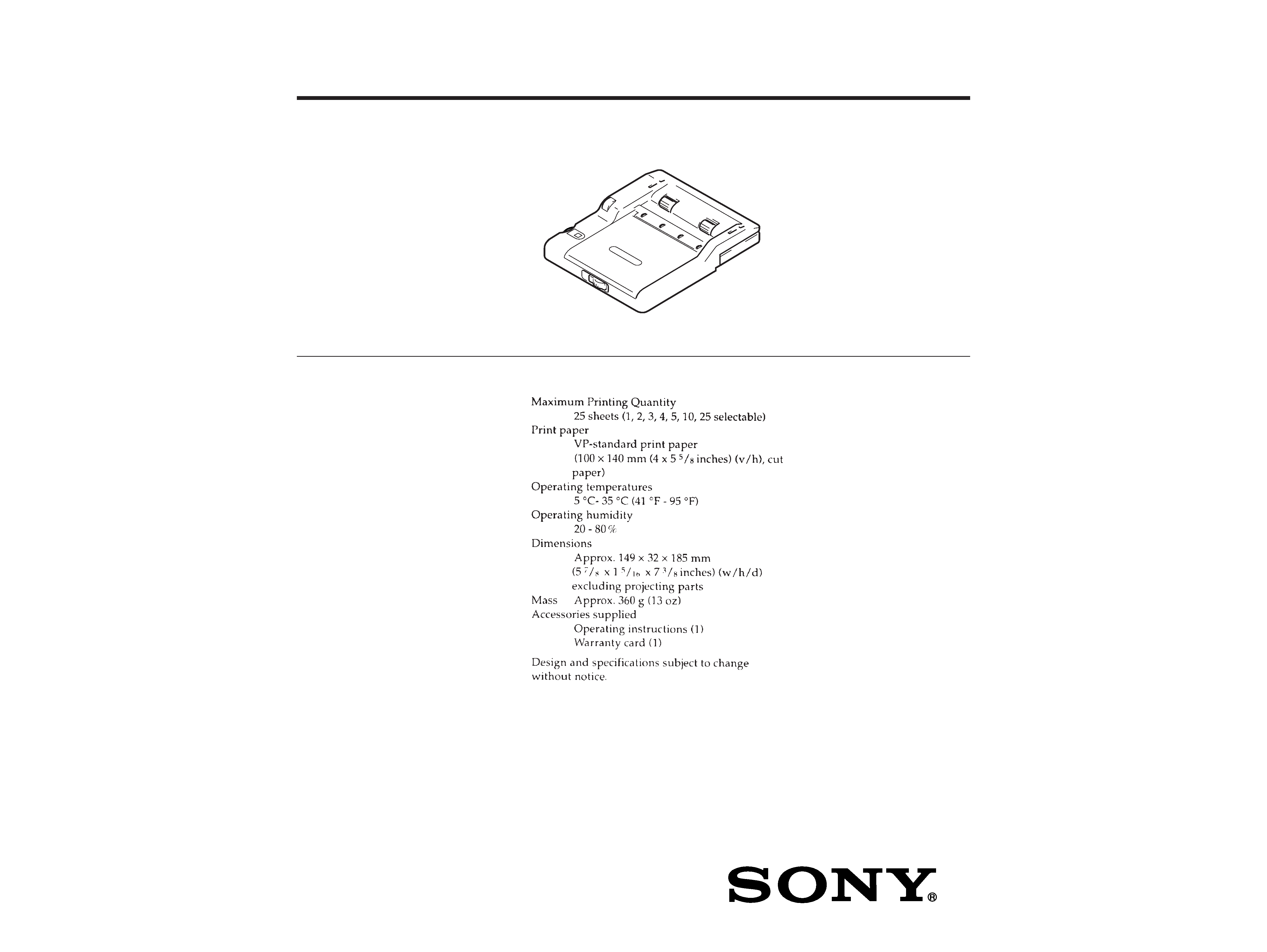
SPECIFICATIONS
AUTOMATIC FEEDER
9-928-119-11
2
ATTENTION AU COMPOSANT AYANT RAPPORT
À LA SÉCURITÉ!!
LES COMPOSANTS IDENTIFIÉS PAR UNE MARQUE
!SUR
LES DIAGRAMMES SCHÉMATIQUES ET LA LISTE DES
PIÈCES SONT CRITIQUES POUR LA SÉCURITÉ DE
FONCTIONNEMENT. NE REMPLACER CES COMPOSANTS
QUE PAR DES PIÈCES SONY DONT LES NUMÉROS
SONT DONNÉS DANS CE MANUEL OU DANS LES
SUPPLÉMENTS PUBLIÉS PAR SONY.
SAFETY-RELATED COMPONENT WARNING !!
COMPONENTS IDENTIFIED BY MARK
! OR DOTTED LINE
WITH MARK
! ON THE SCHEMATIC DIAGRAMS AND IN
THE PARTS LIST ARE CRITICAL TO SAFE OPERATION.
REPLACE THESE COMPONENTS WITH SONY PARTS
WHOSE PART NUMBERS APPEAR AS SHOWN IN THIS
MANUAL OR IN SUPPLEMENTS PUBLISHED BY SONY.
SAFETY CHECK-OUT
After correcting the original service problem, perform the follow-
ing safety checks before releasing the set to the customer:
Check the antenna terminals, metal trim, "metallized" knobs, screws,
and all other exposed metal parts for AC leakage. Check leakage as
described below.
LEAKAGE
The AC leakage from any exposed metal part to earth Ground and
from all exposed metal parts to any exposed metal part having a
return to chassis, must not exceed 0.5 mA (500 microampers). Leak-
age current can be measured by any one of three methods.
1. A commercial leakage tester, such as the Simpson 229 or RCA
WT-540A. Follow the manufacturers' instructions to use these
instruments.
2. A battery-operated AC milliammeter. The Data Precision 245
digital multimeter is suitable for this job.
3. Measuring the voltage drop across a resistor by means of a VOM
or battery-operated AC voltmeter. The "limit" indication is 0.75
V, so analog meters must have an accurate low-voltage scale.
The Simpson 250 and Sanwa SH-63Trd are examples of a pas-
sive VOM that is suitable. Nearly all battery operated digital
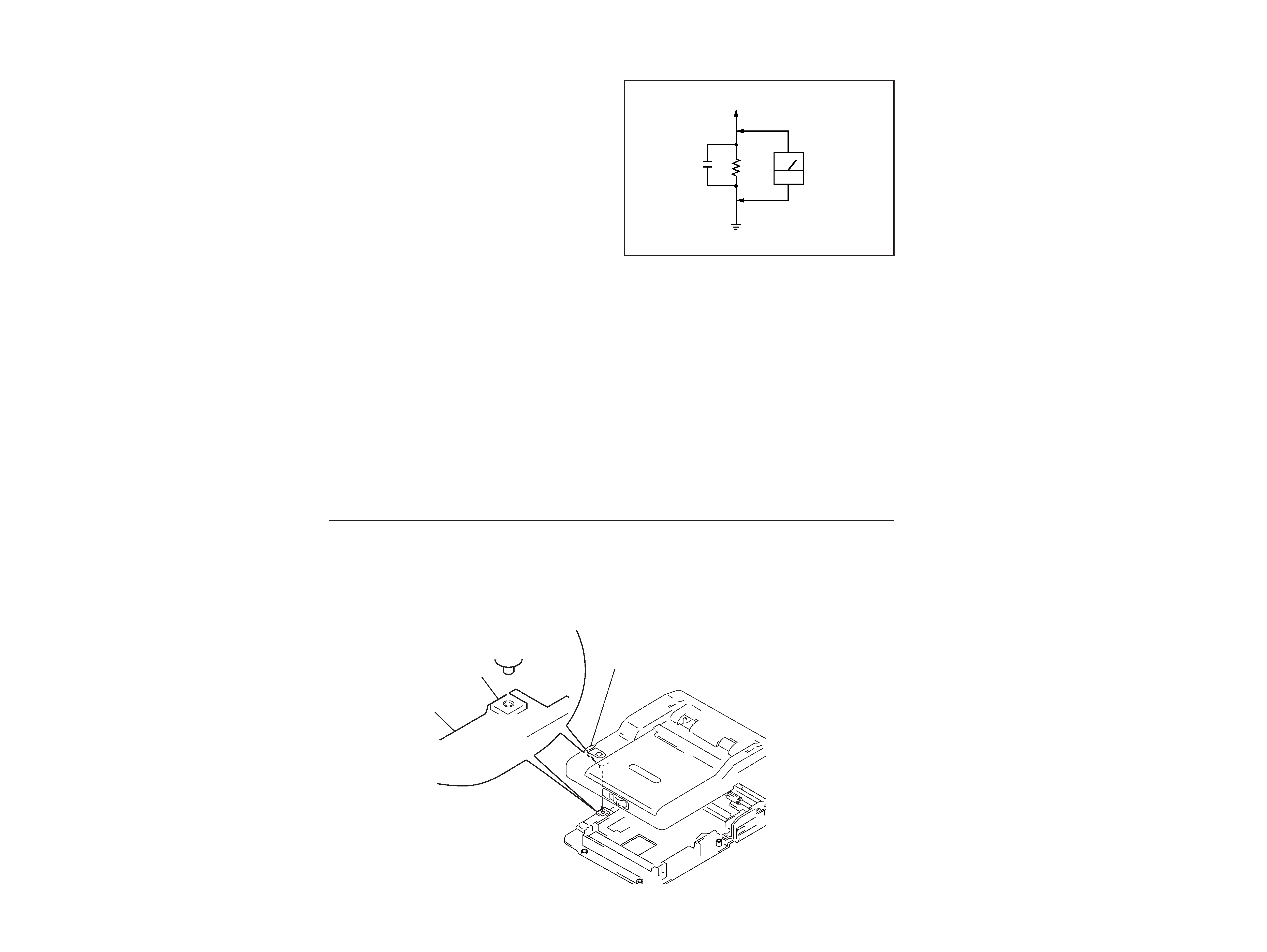
multimeters that have a 2V AC range are suitable. (See Fig. A)
Fig. A. Using an AC voltmeter to check AC leakage.
0.15
µF
To Exposed Metal
Parts on Set
1.5k
AC
voltmeter
(0.75V)
Earth Ground
SECTION 1
SERVICING NOTE
CAUTION FOR INSTALLING
Cabinet (upper) assembly
Install the Indication dial to the switch (S100) on the FR-23 board as shown in the figure.
Fig.1
S100
R-23 board
Indication dial
VPF-A1
4
3
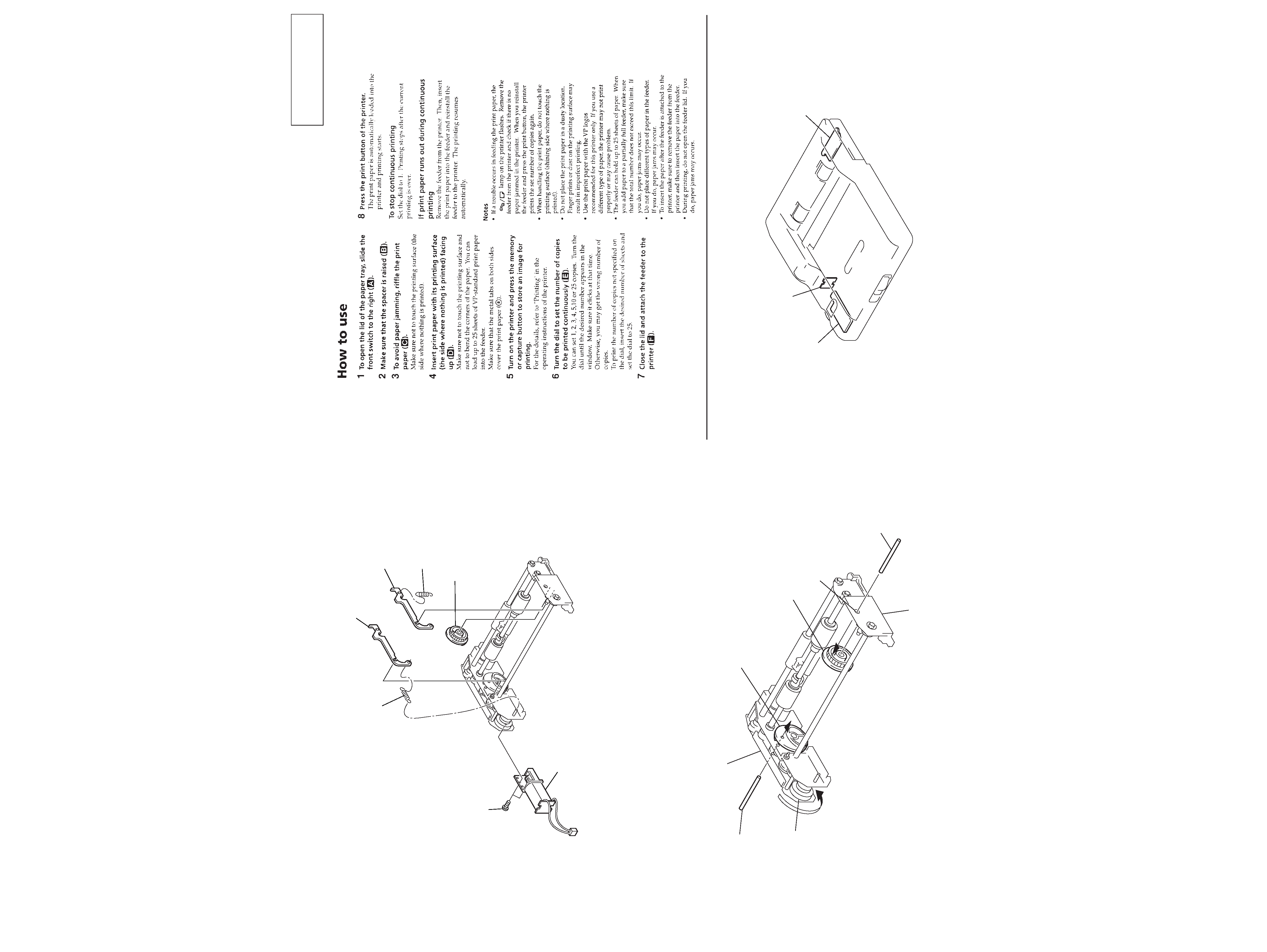
Phase adjusting of Feeder cam assembly
1) Remove each part in nimerical order in the figure.
(Refer to Fig.2)
2) Rotate the gear (A) 8 in the direction of arrow, and pierce the
Pin (ø1) 9 through from a positioning hole on the reinforce-
ment to the feeder cam (L) assembly. (Refer to Fig.3)
3) Pierce the Pin (ø1) !º through a positioning hole on the side
plate (R) in the state of step 2), then install the feeder cam (R)
assembly 7. (Refer to Fig. 3)
4) Pull out the two Pins (ø1) 9 and !º, then install each part 1 to
6 in reverse order of removing. (Refer to Fig.2)
Fig.2
Fig.3
1 Two screws
2 Feeder motor assembly
3 Tension spring
4 Feed lock
6 Feed lock
7 Feeder cam (R) assembly
5 Tension spring
Reinforcement
Feeder cam (L) assembly
Positioning hole
Side plate (R)
7 Feeder cam (R) assembly
!º Pin (ø1)
9 Pin (ø1)
8 Gear (A)
SECTION 2
GENERAL
This section is extracted from
instruction manual.
3-856-684-02
SECTION 3
DIAGRAMS
FR-23 board
FR-35 board
FJ-23 board
VPF-A1
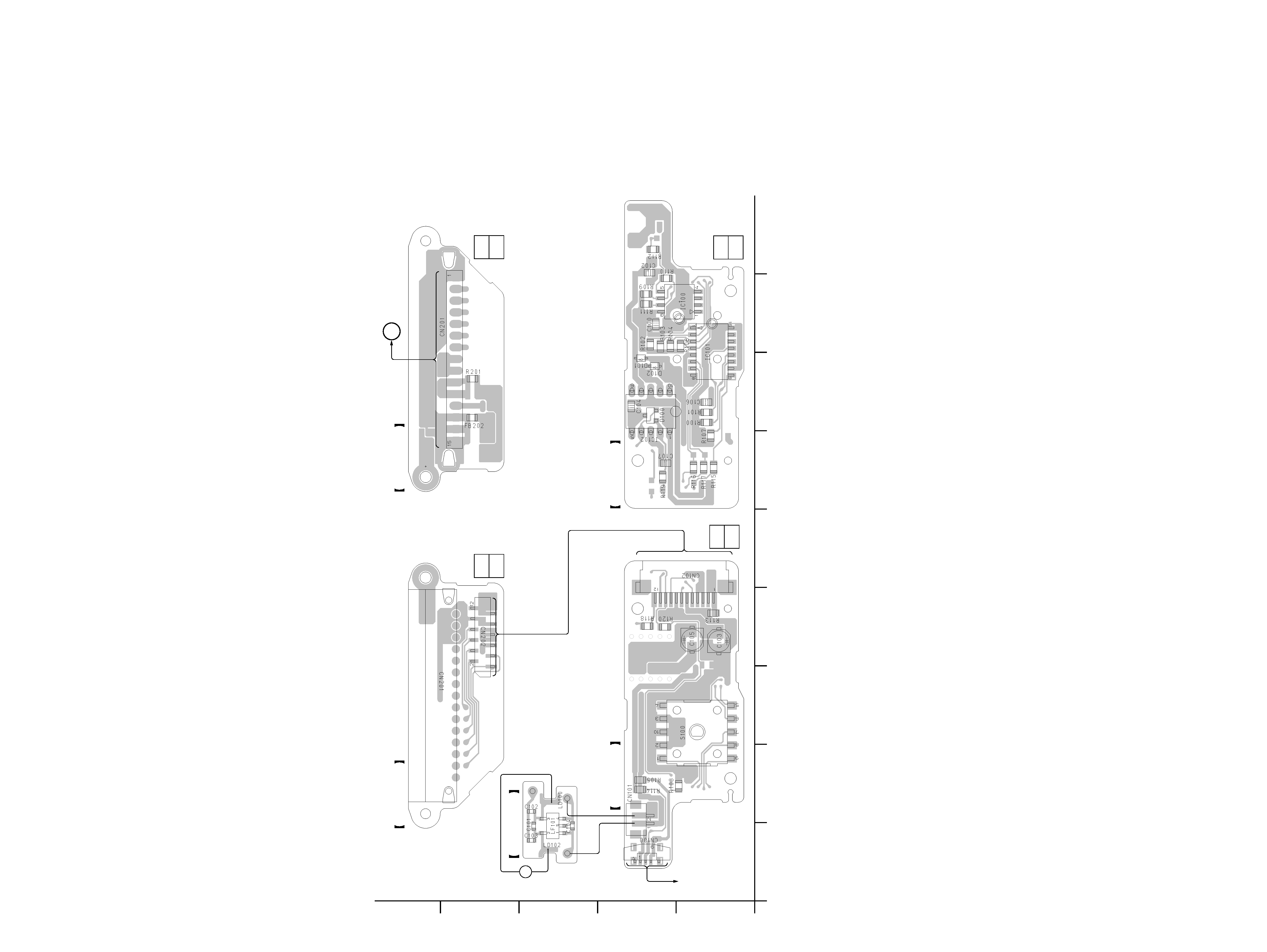
3-1. PRINTED WIRING BOARD AUTO FEEDER SECTION
6
5
Note:
· X : parts extracted from the component side.
·
®
: Through hole.
· b : Pattern from the side which enables seeing.
(The order layuers' patterns are not indicated.)
M
M101
FEEDER
MOTOR
FEEDER
POSITION SENSOR
(FP-701 FLEXIBLE BOARD)
FE-35 BOARD
CN701 (PAGE 7)
B
1-659-936-
11
(11)
1-659-936-
11
(11)
1-659-937-
11
(11)
1-659-937-
11
(11)
FR-35 BOARD
FJ-23 BOARD (SIDE A)
FJ-23 BOARD (SIDE B)
FR-23 BOARD (SIDE B)
FR-23 BOARD (SIDE A)
09
1
E
D
C
B
A
23456789
VPF-A1
8
7
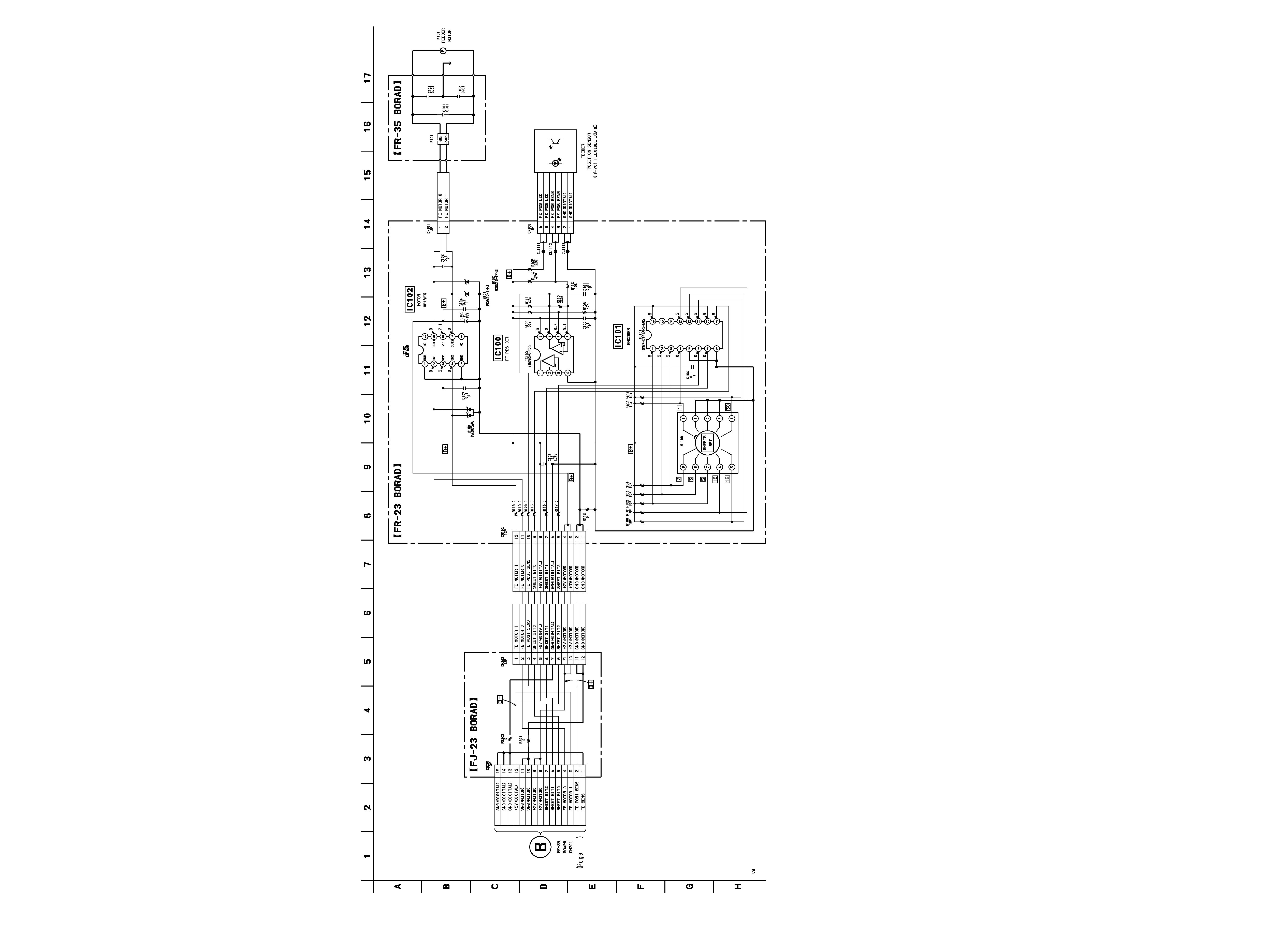
3-2. SCHEMATIC DIAGRAM AUTO FEEDER SECTION