SERVICE MANUAL
EXTERNAL GPS ANTENNA
US Model
Canadian Model
AEP Model
UK Model
VCA-41
Ver. 1.0 2005.12
SPECIFICATIONS
9-879-988-01
2005L05-1
© 2005.12
Sony Corporation
eVehicle Division
Published by Sony Engineering Corporation
GENERAL
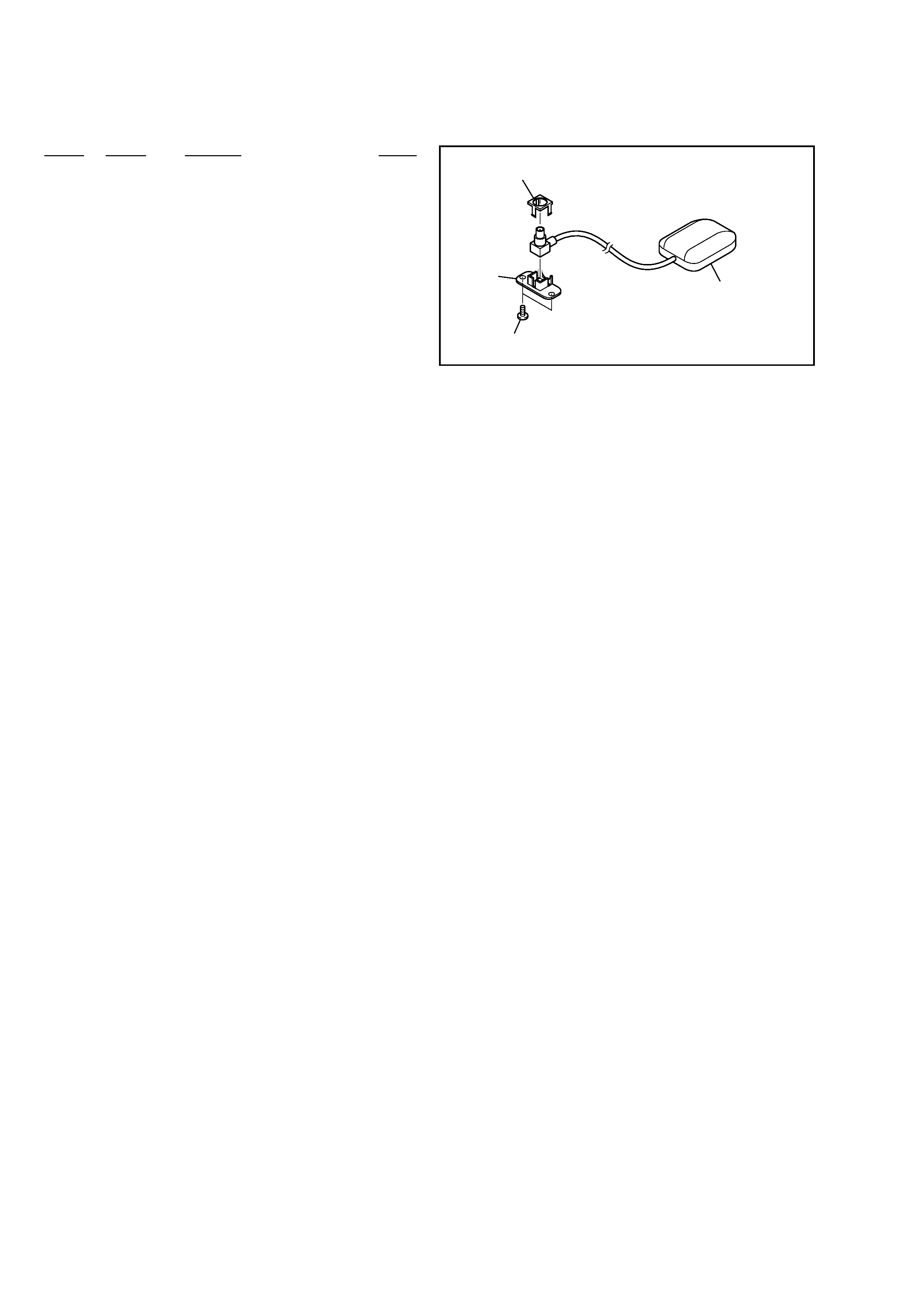
Bottom of cradle
Unterseite der
Anschlussstation
Partie inférieure de la station
d'accueil
Parte inferiore del supporto
Dimensions: Approx. 33 × 13 × 36 mm
(1.3 × 0.5 × 1.4 in) (w × h × d)
Mass: Approx. 110 g (4 oz)
Cord length: Approx. 5 m (16.4 ft)
Design and specifications are subject to change without notice.
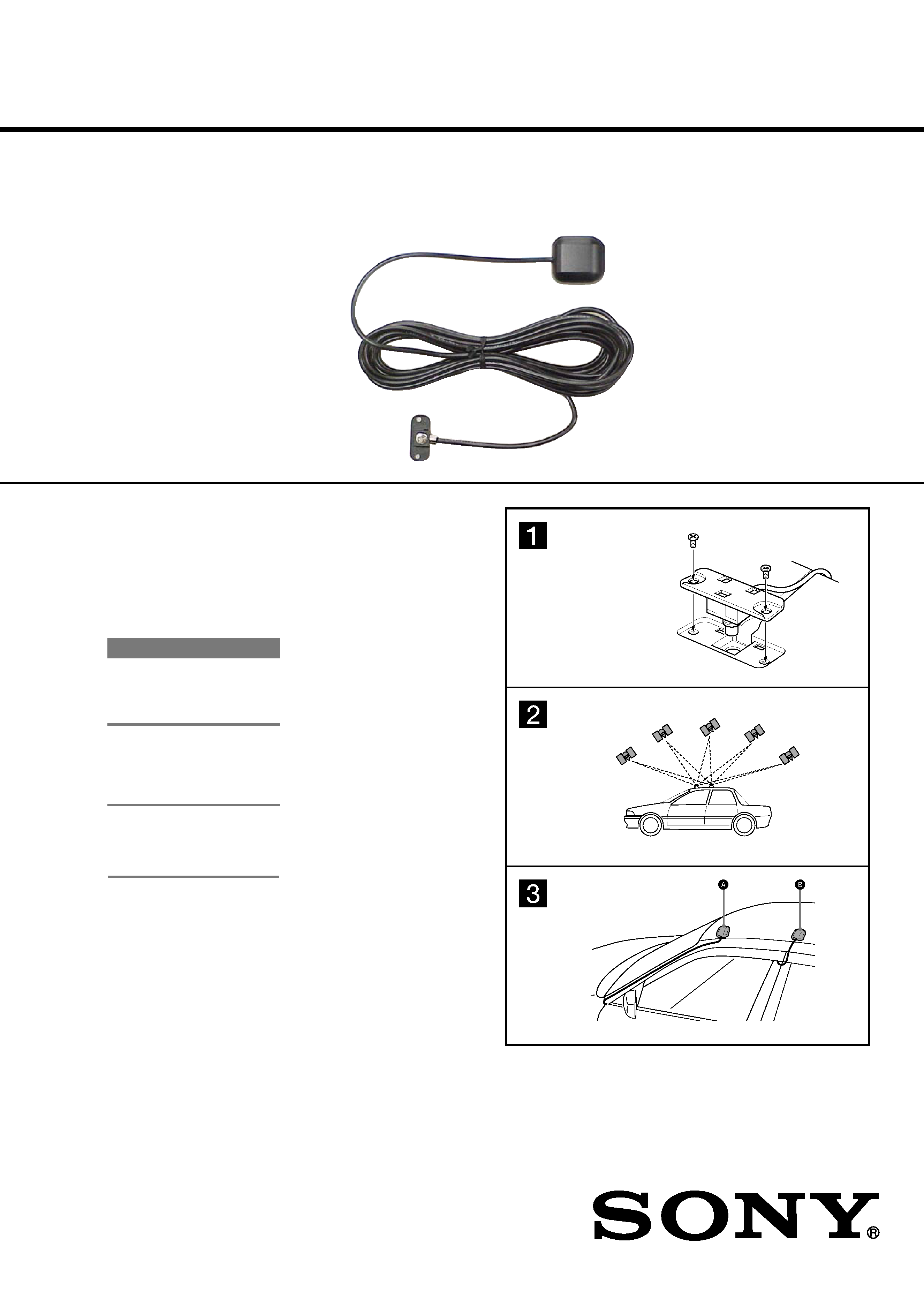
Attaching to a car
Before attaching
· Choose a location where no obstacle blocks GPS
satellite reception so as to achieve best reception.
· Make sure the unit does not interfere with the
operation of car equipment.
· Clean the mounting surface.
Securing the T-shaped connector and
cord to the cradle
1
1
Insert the T-shaped connector and cord into
its cast on the bottom of the cradle*.
* Supplied with the Sony Navigation System.
2
Secure the connector to the cradle with the
supplied 2 screws, using a screwdriver.
Attaching to the roof of a car using
magnet
2
Position the unit horizontally, and where GPS satellite
reception is not blocked by the roof or boot.
Note
Place the unit carefully so as not to damage the car's body
surface.
Installing the cord
3
Roof A
Pass the cord along the windscreen pillar, fender and
molding, then pull it into the car.
Roof B
Pass the cord along the centre pillar, windscreen
pillar inner side and dashboard, then pull it into the
car.
Note
If the car uses a curtain-type side airbag that spreads from
the windscreen pillar over the centre pillar, or a shock-
absorbing structure for its interior, be sure to place the cord
at a distance from it.
Note when installing the cord
Secure the cord using a commercially available cord clamps in
the form of a U-shape if necessary, to prevent rain water from
entering the car along the cord, or the cord from disturbing
driving.
Notes
· Do not allow cord slack outside of the car.
· GPS signals and DC power are flowing through the GPS
aerial cord. When attaching the unit, be careful that the cord
is not caught in any moving parts of the car. A damaged cord
may result in malfunction of the unit.
· When washing your car in an automatic car-wash, detach
the unit from the car. Otherwise the unit may come off and
damage the car's body surface.
· Do not pull the cord when detaching the unit as the cord may
detach itself since the magnet is strong.
· Note that the magnet will not attach to an aluminum or FRP
car body.
On painting the unit
The unit can be painted to match the car's body colour.
However, do not use metallic paint, as it may cause poor
reception or reception error. Do not dismantle the unit for this
purpose.
2
VCA-41
PARTS LIST
Ref. No.
Part No.
Description
Remark
2-664-956-11 MANUAL, INSTRUCTION (ENGLISH, FRENCH,
SPANISH, GERMAN, ITALIAN, DUTCH,
SWEDISH, GREEK, POLISH, PORTUGUESE)
1
2-650-789-01 CASE GPS (UPPER)
2
2-650-790-01 CASE GPS (LOWER)
3
4-672-839-01 HEAD, M3 FLAT
1
not supplied
2
3

3
VCA-41
MEMO

2
VCA-41
REVISION HISTORY
Clicking the version allows you to jump to the revised page.
Also, clicking the version at the upper right on the revised page allows you to jump to the next revised
page.
Ver.
Date
Description of Revision
1.0
2005.12
New