MICROFILM
TXD-RE210
AEP Model
SERVICE MANUAL
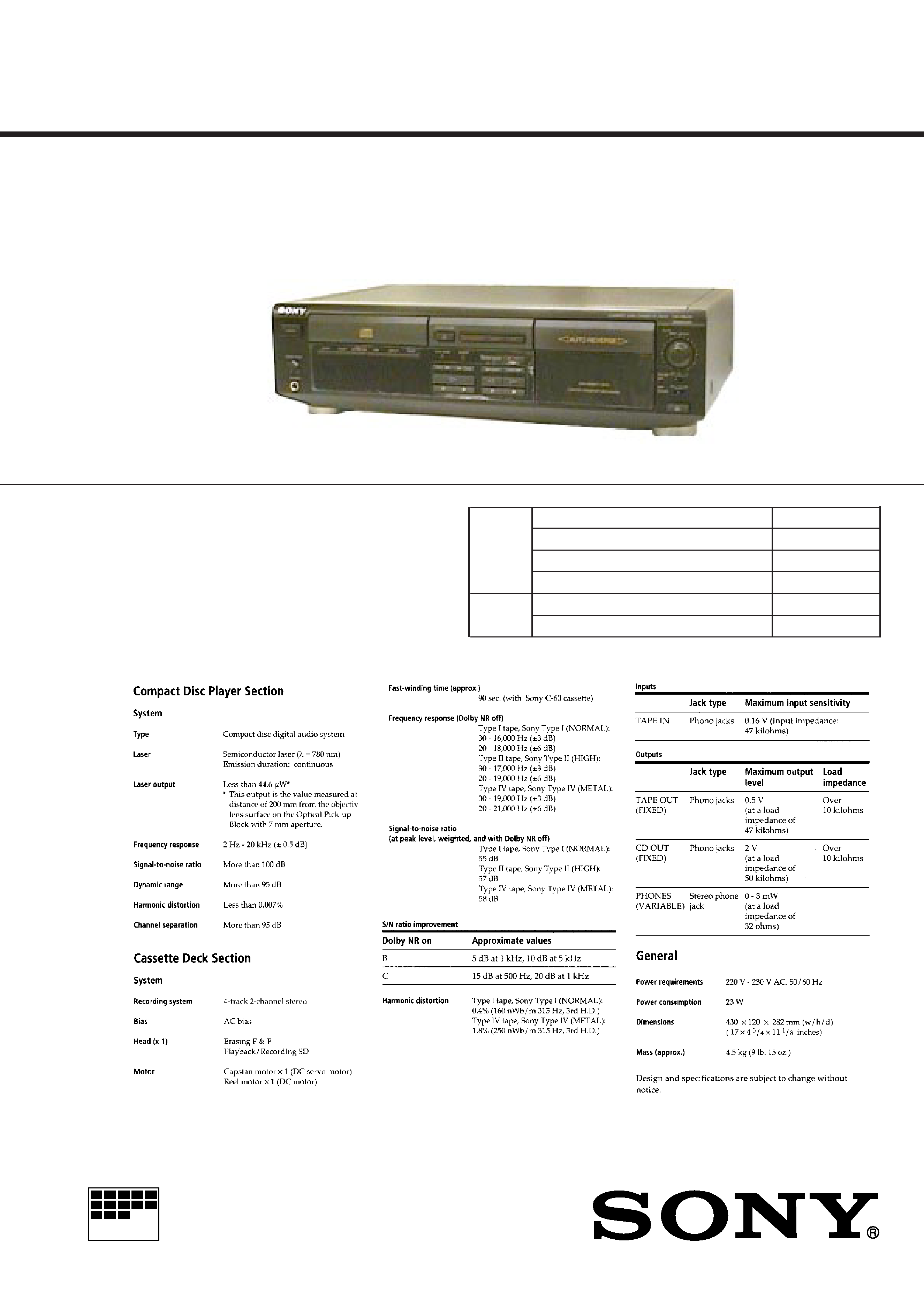
COMPACT DISC CASSETTE DECK
Model Name Using Similar Machanism
NEW
CD
CD Machanism Type
CDM28-5BD23
Section
Base Unit Name
BU-5BD23
Optical Pick-up Type
KSS-213B/S-N
Tape deck Model Name Using Similar Machanism
TXD-R11
Section
Tape Transport Mechanism Type
TCM-190RB52C
Dolby noise reduction manufactured under license from
Dolby Laboratories Licensing Corporation.
"DOLBY" and the double-D symbol
a are trademarks of
Dolby Laboratories Licensing Corporation.
SPECIFICATIONS
2
TABLE OF CONTENTS
Specifications ........................................................................... 1
1.
SERVICING NOTE .......................................................... 3
2.
GENERAL
Location and Function of Controls .................................... 4
3.
DISASSEMBLY
3-1. Front Panel Removal .................................................. 5
3-2. CD Mechanism Removal ........................................... 5
3-3. Mechanism Deck Removal ......................................... 6
4.
ADJUSTMENTS
4-1. Mechanical Adjustments ............................................ 7
4-2. Electrical Adjustments ................................................ 7
5.
EXPLANATION OF IC TERMINALS .......................... 11
6.
DIAGRAMS
6-1. Printed Wiring Boards BD Section ..................... 14
6-2. Schematic Diagram BD Section ......................... 17
6-3. Schematic Diagram Main Section ...................... 22
6-4. Printed Wiring Boards Main Section .................. 27
7.
EXPLODED VIEWS
7-1. Chassis Section ......................................................... 30
7-2. Panel Section ............................................................ 31
7-3. Mechanism Section -1 .............................................. 32
7-4. Mechanism Section -2 .............................................. 33
7-5. CD Mechanism Section -1 ........................................ 34
7-6. CD Mechanism Section -2 ........................................ 35
8.
ELECTRICAL PARTS LIST ........................................ 36
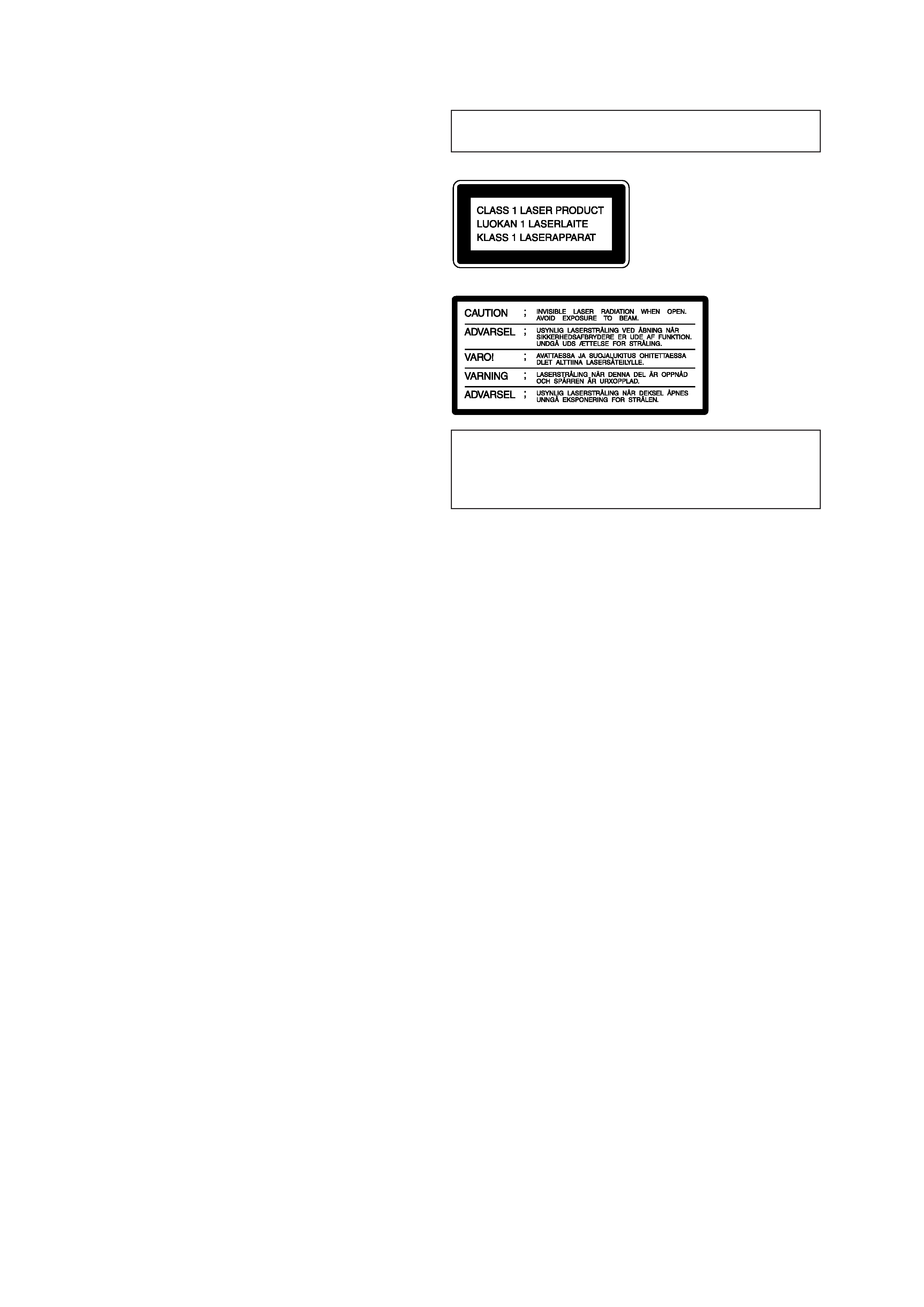
Laser component in this product is capable of emitting radiation
exceeding the limit for Class 1.
This appliance is classified as a
CLASS 1 LASER product.
The CLASS 1 LASER
PRODUCT MARKING is lo-
cated on the rear exterior.
CAUTION
Use of controls or adjustments or performance of procedures other
than those specified herein may result in hazardous radiation ex-
posure.
This caution label
is located inside
the unit.
SAFETY-RELATED COMPONENT WARNING!!
COMPONENTS IDENTIFIED BY MARK
! OR DOTTED LINE
WITH MARK
! ON THE SCHEMATIC DIAGRAMS AND IN THE
PARTS LIST ARE CRITICAL TO SAFE OPERATION.
REPLACE THESE COMPONENTS WITH SONY PARTS WHOSE
PART NUMBERS APPEAR AS SHOWN IN THIS MANUAL OR IN
SUPPLEMENTS PUBLISHED BY SONY.
3
SECTION 1
SERVICING NOTE
NOTES ON HANDLING THE OPTICAL PICK-UP
BLOCK OR BASE UNIT
The laser diode in the optical pick-up block may suffer electrostatic
breakdown because of the potential difference generated by the
charged electrostatic load, etc. on clothing and the human body.
During repair, pay attention to electrostatic breakdown and also use
the procedure in the printed matter which is included in the repair
parts.
The flexible board is easily damaged and should be handled with
care.
NOTES ON LASER DIODE EMISSION CHECK
The laser beam on this model is concentrated so as to be focused on
the disc reflective surface by the objective lens in the optical pick-
up block. Therefore, when checking the laser diode emission, ob-
serve more than 30 cm away from the objective lens.
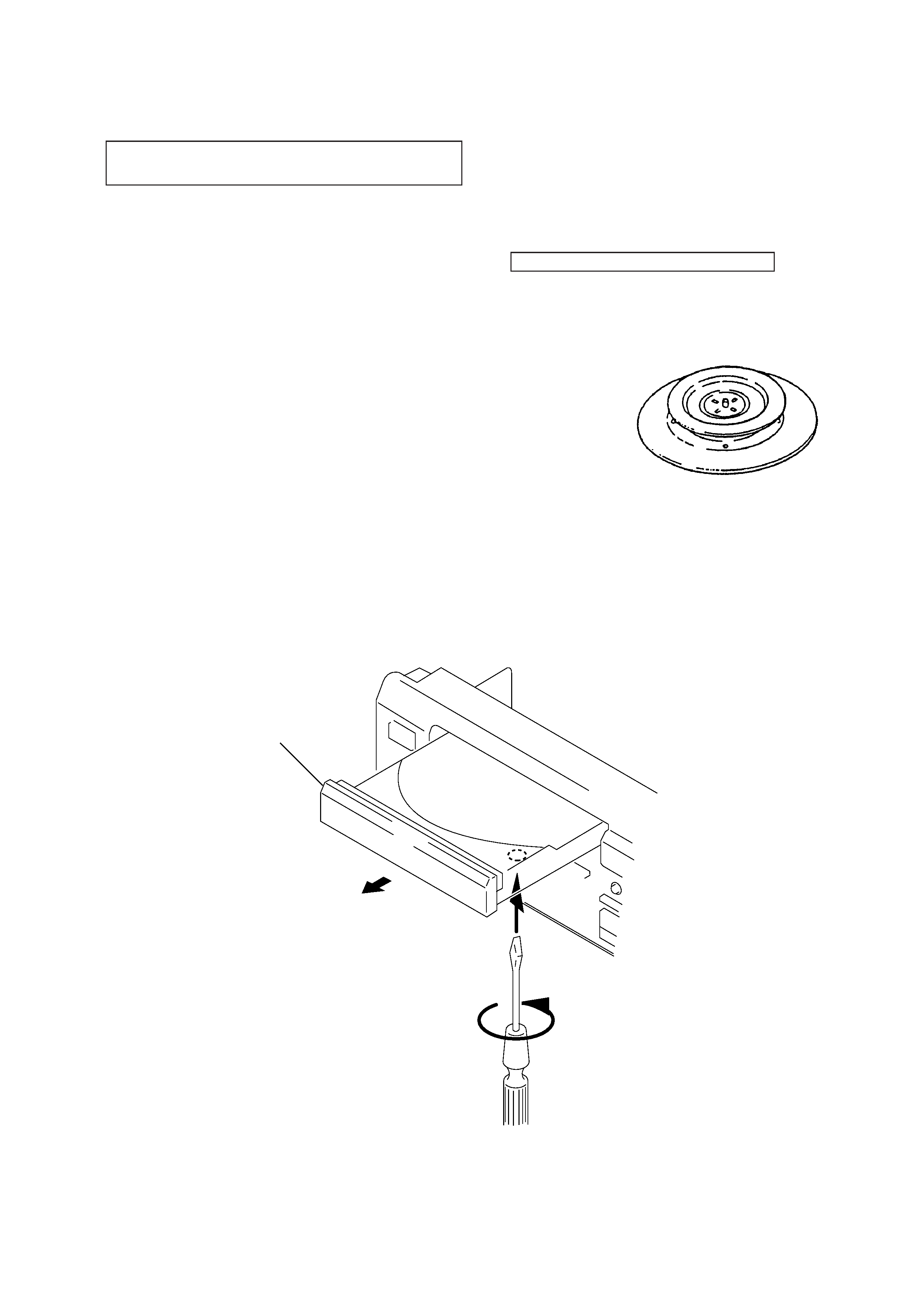
CHUCK PLATE JIG ON REPAIRING
On repairing CD section, playing a disc without the CD lid, use
Chuck Plate Jig.
r
Code number of Chuck Plate Jig : X-4918-255-1
r
Disc table getting out procedure on the power supply is OFF.
1
2
Disc table
3
4
SECTION 2
GENERAL
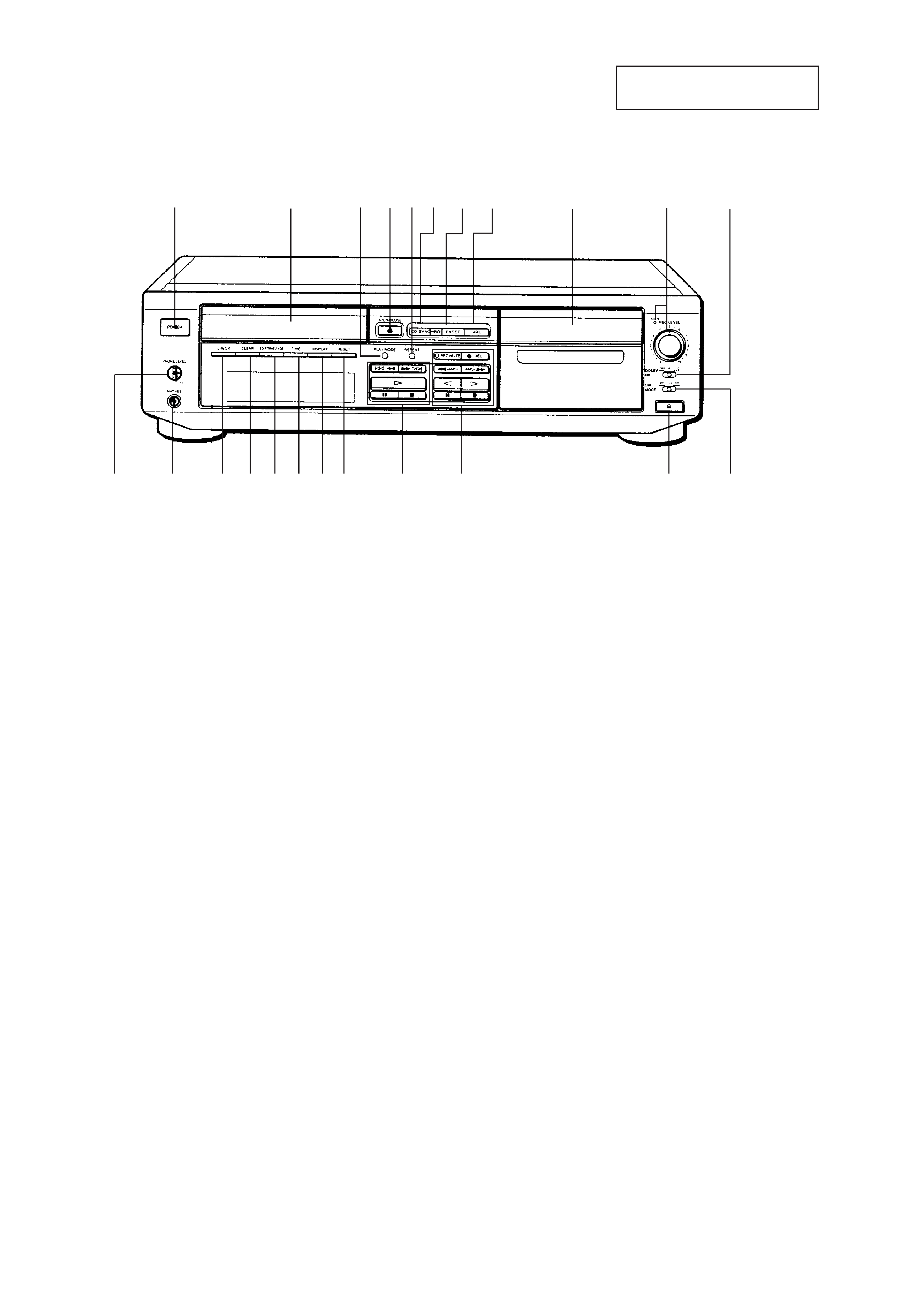
LOCATION AND FUNCTION OF CONTROLS
3
2
4
9
!º
! CD operating buttons
) ± button
0 button
· button
p (stop) button
P (pause) button
!§ RESET button
!¶ DISPLAY button
!· TIME button
!ª EDIT/TIME FADE button
@º CREAR button
@¡ CHECK button
@TM PHONES jack
@£ PHONE LEVEL control
1 POWER switch
2 Disc tray
3 PLAY MODE button
4 OPEN/CLOSE button
5 REPEAT button
6 CD SYNCHRO button
7 FADER button
8 ARL button
9 Cassette deck
!º REC LEVEL control/AUTO indicator
!¡ DOLBY NR switch
!TM DIRection MODE switch
!£ Eject button
!¢ Tape operating buttons
r REC button
R REC MUTE button
0, ) buttons
ª, ·
buttons
p (stop) button
P (pause) button
5 6 7 8
1
!¡
!TM
!¶ !§
@º !ª !·
@¡
!¢
!
@TM
@£
!£
This section is extracted from
instruction manual.
5
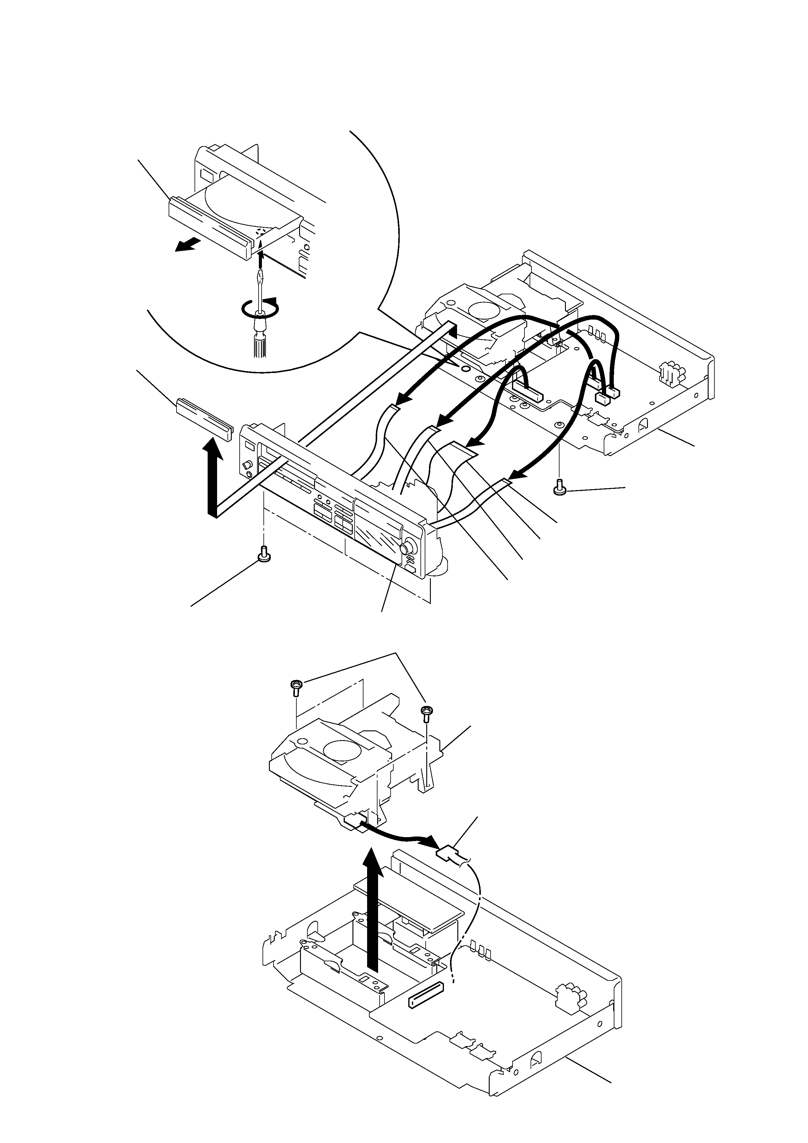
Note : Follow the disassembly procedure in the numerical order given.
1
2
Disc table
Loading panel
Chassis
Front panel assy
6Wire (Flat type) (7 core) to Main board (CN806)
7Wire (Flat type) (23 core) to Main board (CN805)
8Wire (Flat type) (7 core) to Main board (CN801)
9Wire (Flat type) (9 core) to Main board (CN804)
5 Screw (+BV TP 3 x 6)
5 Three Screws (+BV TP 3 x 6)
4
3
Chassis
CD Mechanism
1 Four Screws (+BV TP 3 x 6)
2 SN802 (6P)
3
3-1. FRONT PANEL REMOVAL
3-2. CD MECHANISM REMOVAL
SECTION 3
DISASSEMBLY