1
SERVICE MANUAL
US Model
Canadian Model
E Model
Tourist Model
TMR-IF540R
TRANSMITTER
Ver 1.0 2003. 03
9-877-227-01
2003C0400-1
© 2003. 03
Sony Corporation
Personal Audio Company
Published by Sony Engineering Corporation
Notes on Chip Component Replacement
· Never reuse a disconnected chip component.
· Notice that the minus side of a tantalum capacitor may be
damaged by heat.
Transmitter
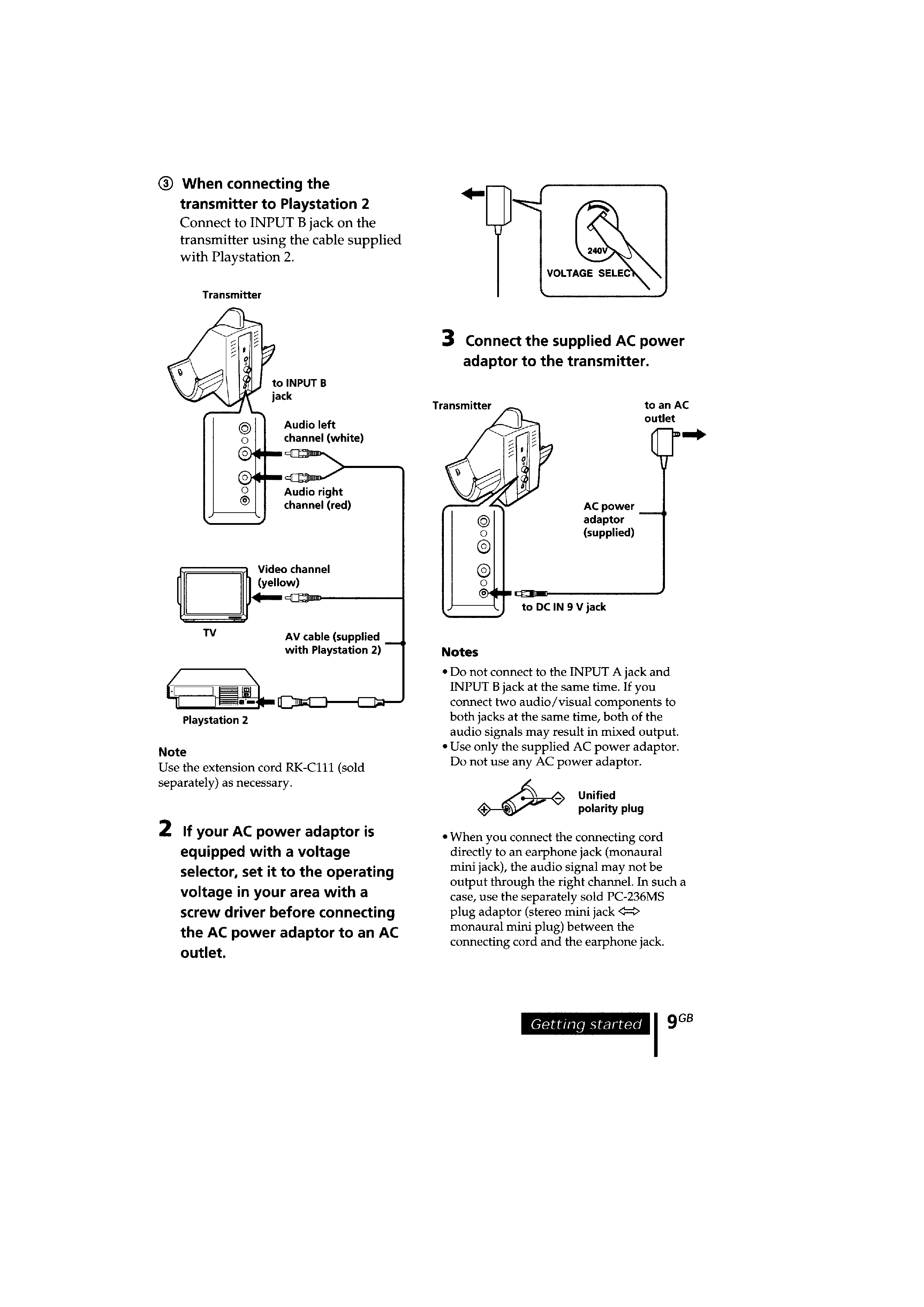
Power source
DC IN 9 V jack accepts
power supplied from the AC
power adaptor for use on the
following voltages:
Where purchased
Operating voltage
US, Canadian
120 V AC, 60 Hz
Japan (exept for
110 V/120 V/220 V/
Japanese
240 V AC, 50/60 Hz
domestic model)
Other countries
220 230 V AC, 50/
60 Hz or 120 V AC,
60 Hz
Audio input
Phono jacks/stereo mini jack
Dimensions
Approx. 133
× 124 × 136 mm
(5 1/4
× 5 × 5 3/8 in.) (w/h/d)
Mass
Approx. 160 g (6 oz.)
Design and specifications are subject to change without
notice.
SPECIFICATIONS
SRS is a trademark of SRS Labs Inc.
SRS Headphones are manufactured under
license from SRS Labs. Inc.
· The TMR-IF540R is the transmitter
that comprises the MDR-IF540RK.
· MDR-IF540RK consists of the following models respectively.
Headphones
MDR-IF540R
Transmitter
TMR-IF540R

2
TABLE OF CONTENTS
1. GENERAL
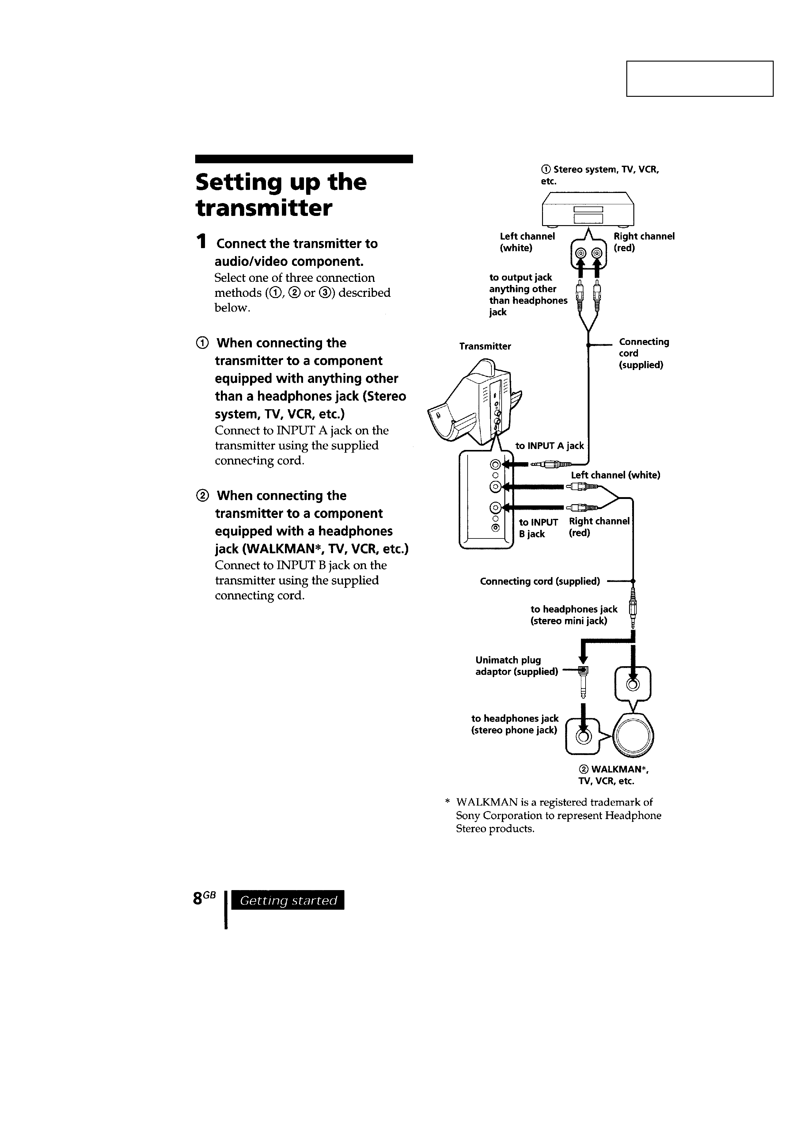
Setting up the transmitter ........................................................ 3
2. DISASSEMBLY
2-1. Cabinet (Upper) Assy .......................................................... 5
2-2. TX Board ............................................................................. 6
3. ELECTRICAL ADJUSTMENTS
Oscillation Frequency Adjustment .......................................... 7
4. DIAGRAMS
4-1. Block Diagram Transmitter Section .............................. 9
4-2. Printed Wiring Board Transmitter Section .................. 10
4-3. Schematic Diagram Transmitter Section ..................... 11
4-4. IC Block Diagram ............................................................. 12
5. EXPLODED VIEW
5-1. Transmitter Section ........................................................... 13
6. ELECTRICAL PARTS LIST ........................................ 14
TMR-IF540R
3
TMR-IF540R
SECTION 1
GENERAL
This section is extracted
from instruction manual.
4
TMR-IF540R
5
TMR-IF540R
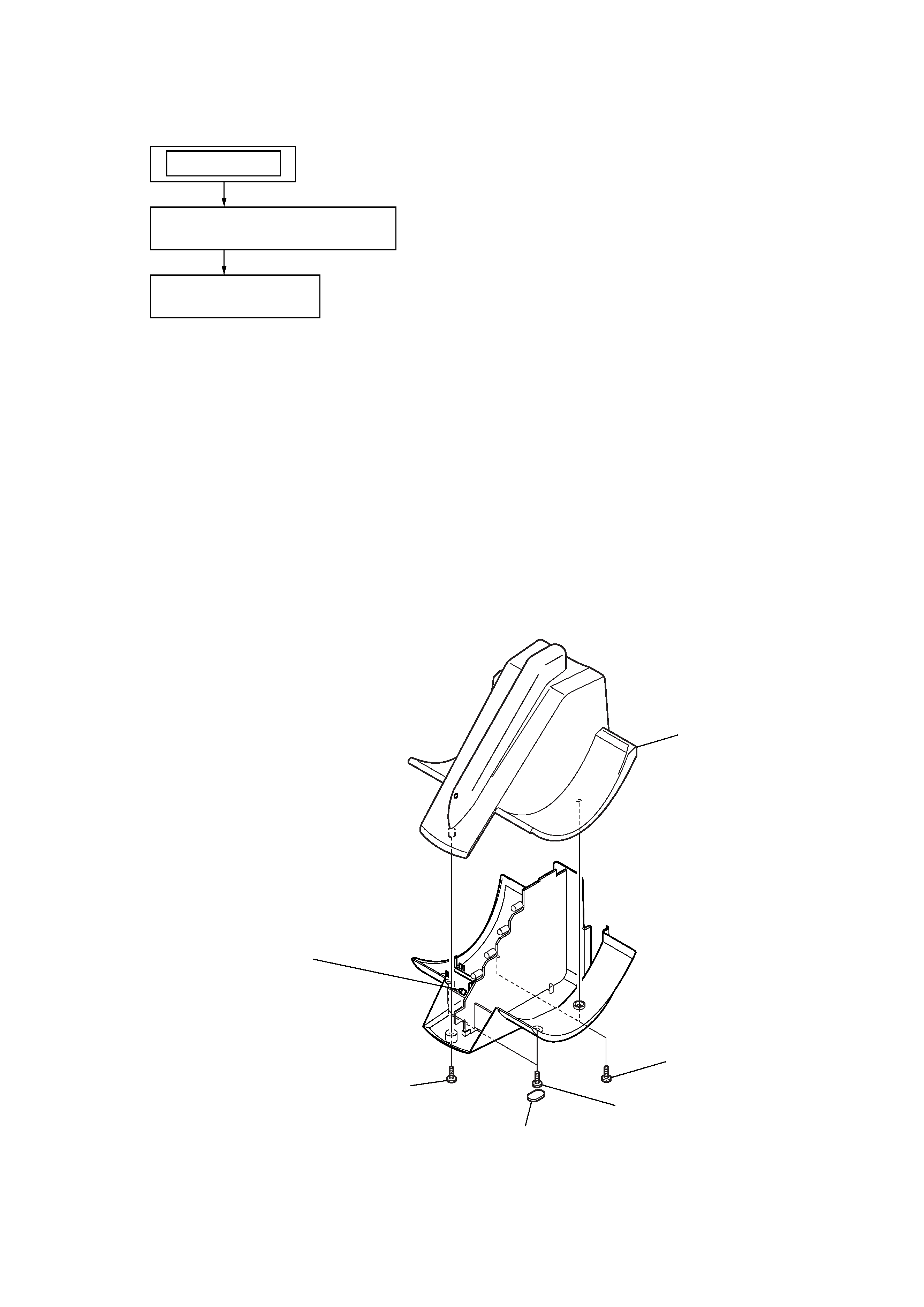
Note : This set can be disassemble according to the following sequence.
SECTION 2
DISASSEMBLY
2-1. CABINET (UPPER) ASSY
Note : Follow the disassembly procedure in the numerical order given.
2-1.
CABINET (UPPER) ASSY
(Page 5)
SET
2-2.
TX BOARD
(Page 6)
1
P 2x6
3
P 2x6
4
P 2x6
5
cabinet (upper) assy
2
protection sheet
Note : Insert this in the LED hole
in the cabinet (upper) assy
when installing.