Ver 1.0 2001.04
TL-HP90
SERVICE MANUAL
HANDS FREE TELEPHONE
SPECIFICATIONS
US Model
9-873-109-11
2001D0200-1
© 2001.4
Dial signal
Tone, 10 pps (pulse) selectable
Dimensions
Approx. 37/8 X 31/8 X 51/2 inches (w/h/d)
(98 X 77 X 137.5 mm)
Mass
Approx. 9.17 oz
(260 g)
Supplied accessories
Telephone line code: approx. 7 ft. (2m)
Stereo audio cable (stereo mini-plug):
approx. 3.5 ft. (1m)
Headset TL-DR0140
Headset hanger
Directories
Headset (TL-DR0140)
Dimension (Cord)
Approx. 7 ft. (2m)
Dimension (Plug)
3.5 mm dia.
Mass
Approx. 0.88 oz (25 g) (without cord)
<Receiver>
Type
Open air dynamic
Driver units
30 mm dia. (CCAW Voice coil)
Sensitivity
104 dB/mW
Impedance
24
Maximum input power
1000 mW (IEC)
<Microphone>
Type
Close-talking pipe microphone
Unit
Back electret condenser
Output impedance
Under 2.2 k
Closed circuit voltage level
-47 dB (0 dB = 1 V/Pa)
Design and specifications are subject to change without notice.
Photo : TL-HP90
Photo : TL-DR0140
Sony Corporation
Personal Audio Company
Shinagawa Tec Service Manual Production Group
2
TL-HP90
Specifications ........................................................................... 1
1. GENERAL ...................................................................... 2
2. DISASSEMBLY
2-1. Case (Upper) , Case (Lower) ...................................... 5
2-2. Main Board ................................................................. 5
2-3. Volume Board, Key Board .......................................... 6
3. DIAGRAMS
3-1. Block Diagram ............................................................ 7
3-2. Schematic Diagram ..................................................... 8
3-3. Printed Wiring Boards Main Section .................... 9
4-4. Printed Wiring Boards Key Section .................... 10
4. EXPLODED VIEWS .................................................. 13
5. ELECTRICAL PARTS LIST ................................... 14
TABLE OF CONTENTS
SECTION 1
GENERAL
This section is extracted from
instruction manual.
Notes on chip component replacement
· Never reuse a disconnected chip component.
· Notice that the minus side of a tantalum capacitor may be dam-
aged by heat.
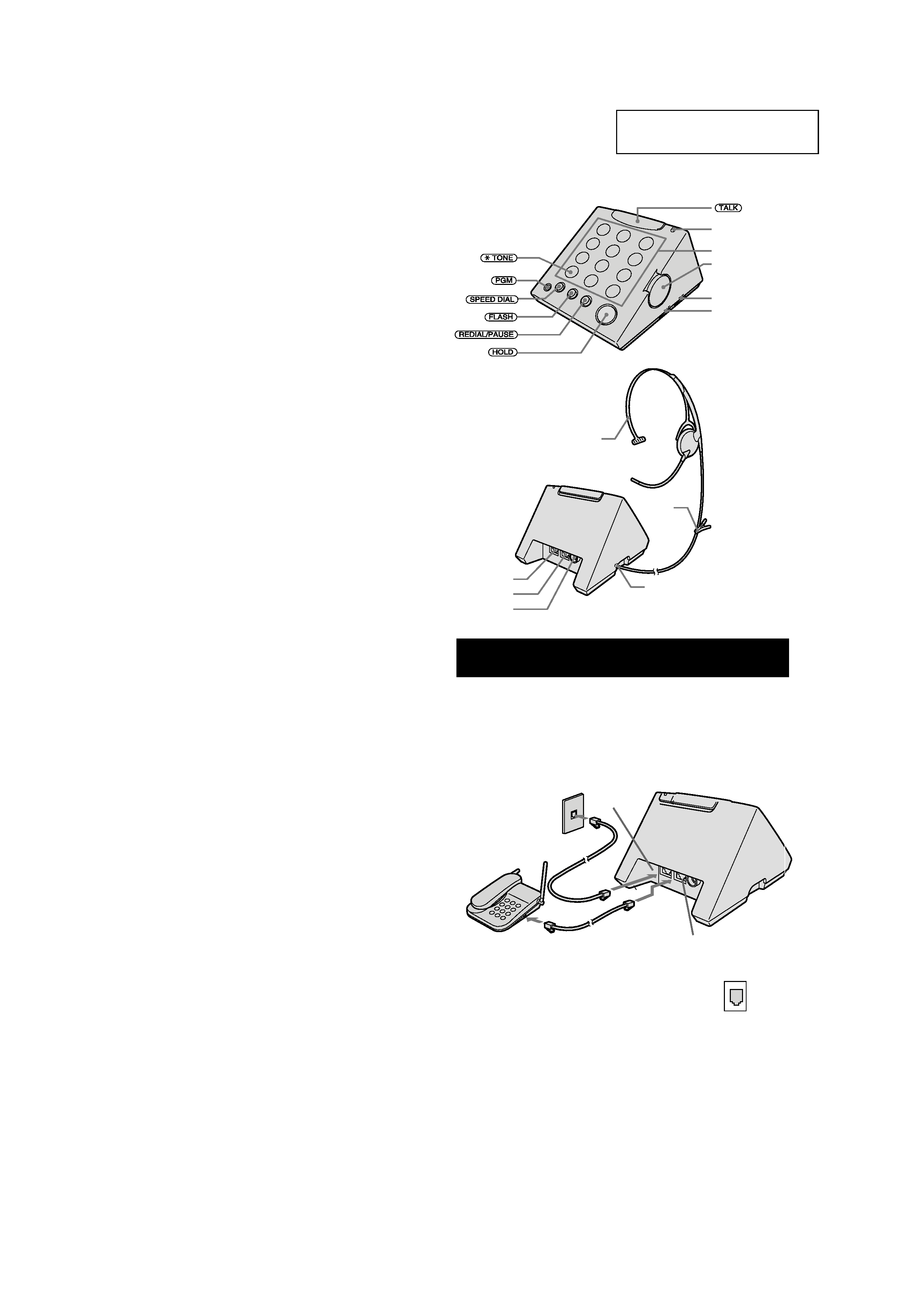
Identifying the part
Lamp
Dialing keys
HEADSET VOLUME
(TEL) control
RINGER LEVEL
switch
DIAL MODE switch
HEADSET jack
TEL/DATA jack
LINE jack
AUDIO IN jack
clip
Headset
Modular
Setting up the phone
Connect the phone
1Connect the telephone line cord (supplied) to the LINE jack,
and to a telephone outlet.
2Connect the telephone line cord (not supplied) to the TEL/
DATA jack and to other phone or the modem if necessary.
Tip
If your telephone outlet is not modular, contact your telephone
service company for assistance.
1
2
To telephone
outlet
Telephone line cord
(supplied)
Telephone line cord
(not supplied)
LINE jack
TEL/DATA jack
To TEL/DATA
jack
To LINE jack
3
TL-HP90
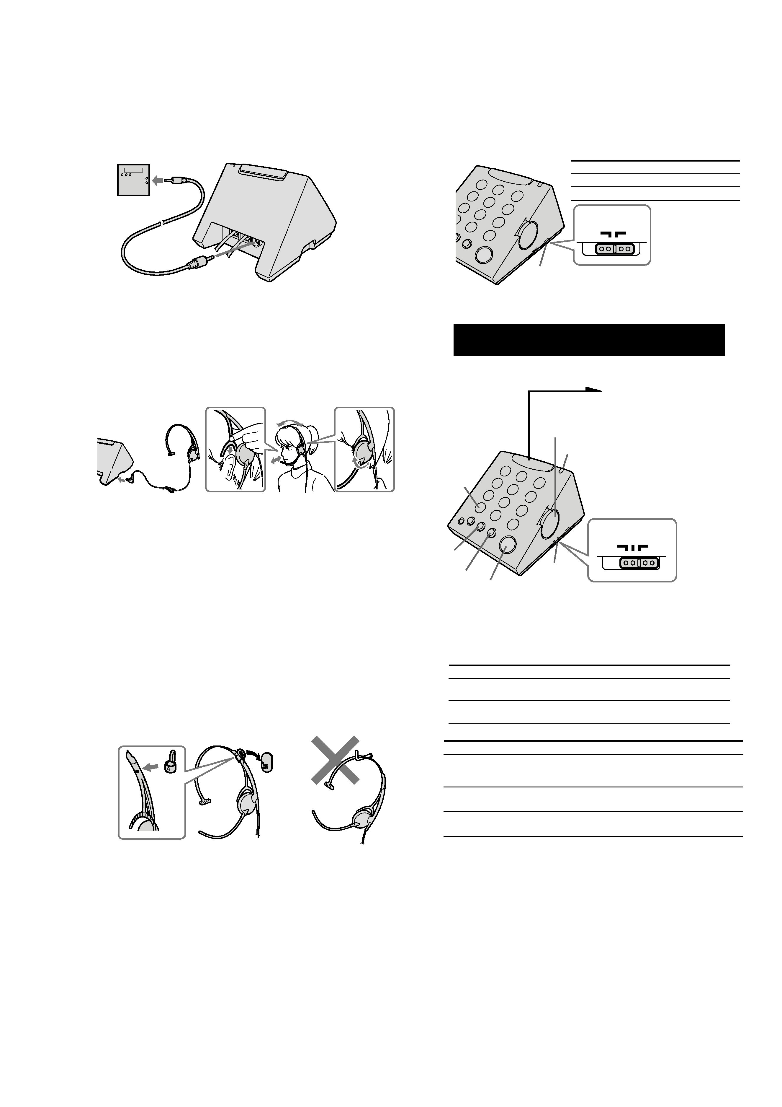
Connect the headset
1Connect the headset plug to the HEADSET jack.
2Place the earpiece support unit behind the top of your ear.
3Adjust the length of the headband so that the headset fits on
your ear.
4The earpiece can be rotated so it fits comfortably over either ear.
5Position the headset microphone so that it is placed near the mouth.
Notes
·
Listening with headset at high volume may affect your hearing.
·
The earpad may deteriorate due to long-term storage or use. If you need to
replacing the earpad, it can be purchase separately (EP-Q1).
Tip
You can use the headset on either your right or left ear.
12
3
4
5
Listening to music, etc. from an external equipment
If you want to listen to music, etc. from the external equipment, you can do
it using the headset during TALK off status.
Notes
·
When you are listening to music, etc. with the external equipment connected to
AUDIO IN jack, volume control on the headset is not available. Volume control is
available with the connected equipment.
Also, turning off the sound from the connected equipment can be done either by
shutting down the power for the external equipment or by pulling out the stereo
audio cable from AUDIO IN jack on this unit.
·
During conversation, the voice from an external equipment cannot be heard.
·
The sound of this unit is a monaural type.
Stereo audio
cable (supplied)
To the headphone jack
(stereo mini-plug)
To AUDIO IN jack
(stereo mini-plug)
e.g.,
cassette player,
radio (not supplied)
Using the headset hunger
The headset can be hung on the hook (supplied) by mounting the handset
hanger (supplied) on the headset.
1 Attach the headset hanger to the headset from the slit as
illustration A.
Be sure to insert the protrusion of the headset hanger to the
projection of the headset.
2 Hang the headset hanger on the hook.
Note
Do not hang the headset on as illustration B.
2
1
A
B
OFF
RINGER LEVEL
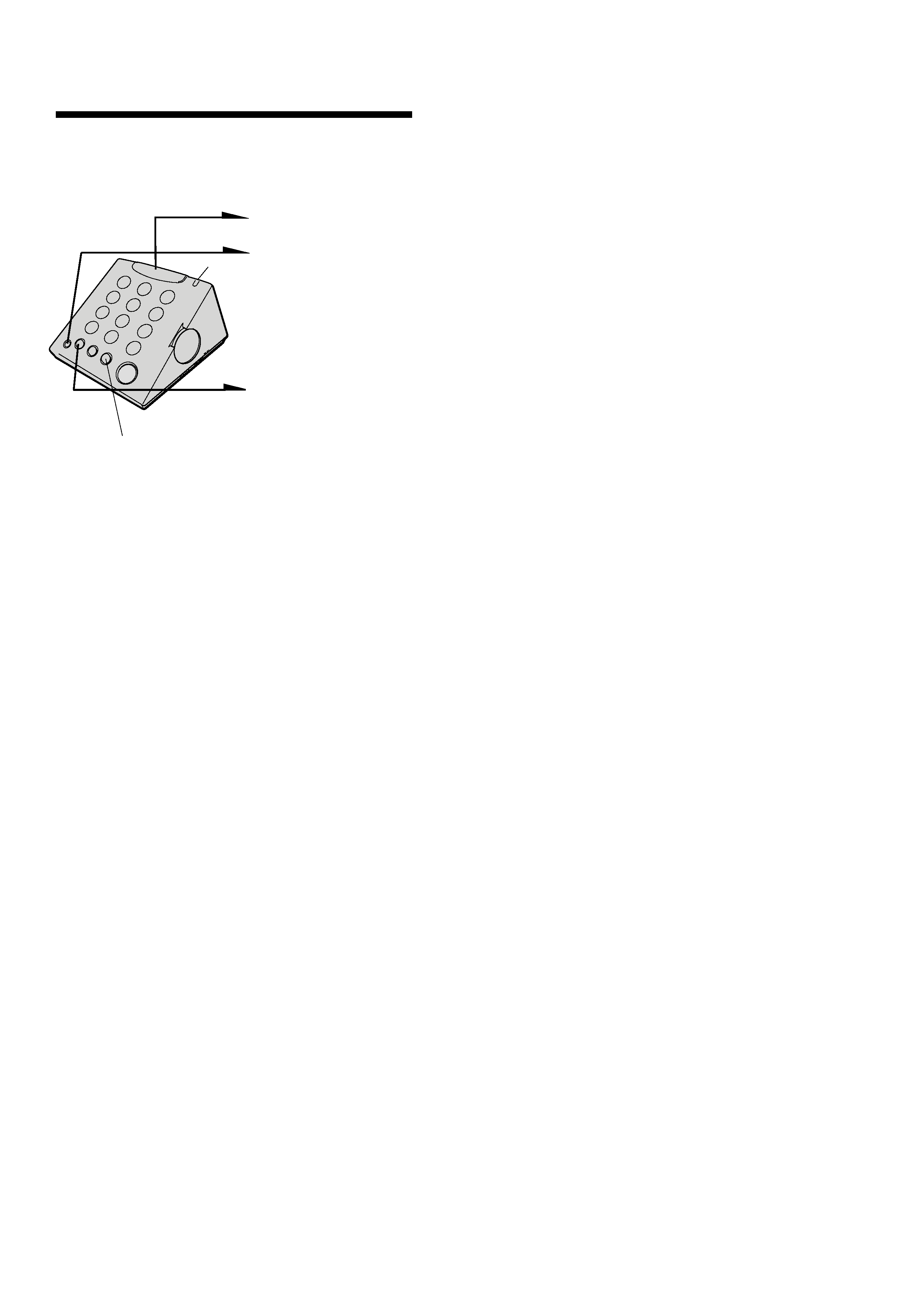
Making and receiving calls
Making a call
1 Press (TALK).
The lamp lights up.
You hear a dial tone.
2 Dial a phone
number.
3 When you're done
talking, press
(TALK).
The lamp goes off.
DIAL MODE
switch
(REDIAL/PAUSE)
(* TONE)
(FLASH)
RINGER
LEVEL
switch
(HOLD)
HEADSET
VOLUME
(TEL)
P
DIAL MODE
T
If your dialing system is to
Set the switch
Tone
T
Pulse
P
Lamp
Choose the dialing mode
For the phone to work properly, select an appropriate dialing mode (tone or
pulse).
Depending on your dialing system, set the
DIAL MODE switch as follows:
If you aren't sure of your dialing system
Make a trial call with the DIAL MODE switch set to T. If the call connects,
leave the switch as is; otherwise, set the switch to P.
Receiving a call
When you hear the phone ring, press (TALK) . When you're done talking,
press (TALK)again.
Additional tasks
Do this
Set the RINGER LEVEL switch to H (high), L (low)
or OFF
Turn the HEADSET VOLUME (TEL) up to increase
the receiver volume or down to decrease it.
(continued)
To
Adjust the ringer level
Adjust the receiver volume
Redialing
1 Press (TALK).
The lamp lights up.
2 Press (REDIAL/PAUSE).
Notes
· If the number last dialed exceeds 31 digits for tone dialing or 32 digits for pulse
dialing, the number cannot be dialed.
· The tone and pause are each counted as one digit.
Note
Pressing (HOLD) during dialing may stop transmission of the dial signal, causing you
to dial the wrong phone number.
To
Switch to tone dialing
temporarily
Put a call on hold
Switch to another call
("call waiting" service*)
Do this
Press (* TONE) after you're connected.
The line will remain in tone dialing until
disconnected.
Press (HOLD). The HOLD button lights up.
Press (HOLD) again to resume the conversation.
Press (FLASH) .
Press (FLASH) again to return to the first caller.
* You need to subscribe to this service with your telephone company.
4
TL-HP90
Speed dialing
You can dial with a touch of a few buttons by storing a phone number on a
dialing button. You can store up to 10 different phone numbers.
Storing phone numbers
1 Press (TALK).
The lamp lights up.
2 Press (PGM).
3 Enter the phone number
you want to store.
You can enter up to 16
digits for pulse dialing
or 15 digits for tone
dialing. Note that tone
and pause are each
counted as one digit.
4 Press (SPEED DIAL).
5 Press one of the dialing
buttons ( (0) to (9)) for
the phone number to be
stored.
And the number is stored.
6 Press (TALK).
The lamp goes off.
Tips
·
If you enter a wrong number, start from the beginning.
·
Use the supplied directory to write down what you stored on the speed dialing
numbers.
To store a number to be dialed via Private Branch
Exchange (PBX)
Before entering a phone number in step 3, do as follows:
1 Enter the outside line access digit (e.g. 9).
2 Press (REDIAL/PAUSE).
To change a stored number
Store a new number as described above, and the old number will erased.
Making calls with speed dialing
1 Press (TALK).
The lamp lights up.
2 Press (SPEED DIAL).
3 Enter the desired speed dialing number ((0) to (9)).
The phone number stored in the speed dialing number will be
dialed.
Note
If this unit is disconnected from the line for 10 minutes or more, the stored speed
dialing data is deleted from the memory.
Lamp
(REDIAL/PAUSE)
5
TL-HP90
SECTION 2
DISASSEMBLY
2-1. CASE (UPPER), CASE (LOWER)
Note : Follow the disassembly procedure in the numerical order given.
3 Connector (4 pin)
(CN301)
1 Screw(+BTP3X10)
1 Screw (+BTP3X10)
1 Screw (+BTP3X10)
2 Connector (3 pin)
(CN101)
4 Connector (14 pin)
(CN401)
Case (upper)
Case (lower)
5
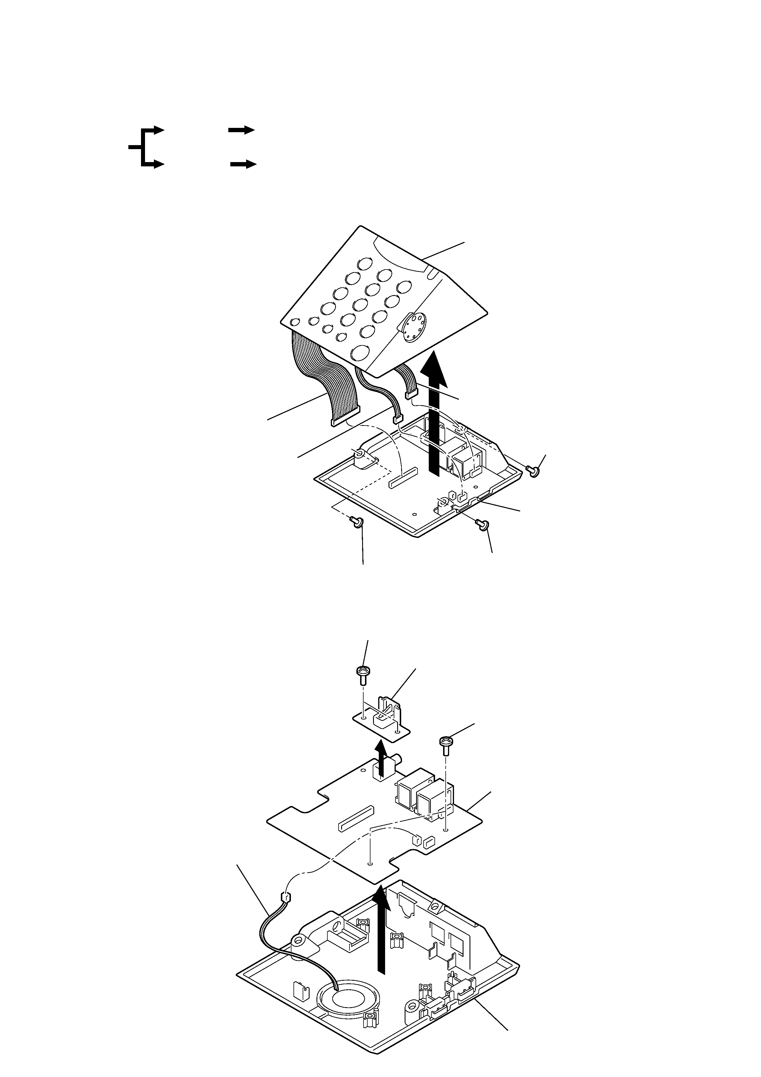
2-2. MAIN BOARD
Case (upper)
Volume board, key board
Main board
Case (lower)
Set
1 Screws (+BTP2.6X8)
4 Screws (+BTP2.6X8)
3 Connector (2 pin)
(CN201)
Holder (jack)
Main board
Case (lower)
2
5