TCS-60DV
US Model
Canadian Model
AEP Model
E Model
SERVICE MANUAL
CASSETTE CORDER
SPECIFICATIONS
Model Name Using Similar Mechanism
TCM-50DV
Tape Transport Mechanism Type
MT-50-30
Recording system
4-track 2 channel stereo
Tape speed
4.8 cm/s or 2.4 cm/s
Frequency range
250 8,000 Hz using nomal (TYPE1) cassette
(with REC TIME switch at "NORMAL")
Speaker
Approx. 3.6 cm (17/16 in.) dia.
×2
Power output
Speakers
: 160 mW + 160 mW
(at 10 % harmonic distortion)
Headphones : 6 mW + 6 mW
(at 10 % harmonic distortion)
Input
Microphone input jack (minijack) sensitivity
0.2 mV for 3
or lower impedance
microphone
Output
2 (headphones) jack (minijack) for
8 300
earphone
Variable range of the tape speed
From approx. +25 % to 15 %
(with REC TIME switch at "NOMAL")
Power requirements 3 V DC batteries AA (R6)
×2/
External DC 3 V power sources
Dimensions (w/h/d)(incl. projecting parts and controls)
Approx. 88.7
× 113.4 × 41.3 mm
(31/2
× 41/2 × 111/16 inches), incl.
Mass
Approx. 280 g (9.9 oz)
Design and specifications are subject to change without notice
Sony Corporation
Personal Audio Company
Published by Sony Engineering Corporation
9-926-969-12
2004G16-1
© 2004.07
Ver 1.2 2004. 07

-- 2 --
TABLE OF CONTENTS
Notes on chip component replacement
· Never reuse a disconnected chip component.
· Notice that the minus side of a tantalum capacitor may be
damaged by heat.
Flexible Circuit Board Repairing
· Keep the temperature of soldering iron around 270°C
during repairing.
· Do not touch the soldering iron on the same conductor of the
circuit board (within 3 times).
· Be careful not to apply force on the conductor when soldering
or unsoldering.
1. SERVICE NOTE ······························································· 3
2. GENERAL ·········································································· 4
3. DISASSEMBLY
3-1. Cabinet (rear) Assy, Lid Sub Assy, Cassette ··················· 5
3-2. MAIN Board, Mechanism Deck ····································· 5
3-3. Belt ·················································································· 6
3-4. Head ················································································ 6
3-5. Motor, DC ······································································· 7
3-6. Precaution For Attaching The MAIN Board ··················· 7
4. ADJUSTMENT ································································· 8
5. DIAGRAMS
5-1. Block Diagram ································································ 9
5-2. Schematic Diagram ······················································· 11
5-3. Printed Wiring Board MAIN Section ······················ 15
5-4. Printed Wiring Board LED Section ························· 20
5-5. IC Block Diagrams ······················································· 24
5-6. IC Pin Function Discription ·········································· 26
6. EXPLODED VIEWS
6-1. MAIN Section -1 ·························································· 27
6-2. MAIN Section -2 ·························································· 28
6-3. Mechanism Deck Section -1 ········································· 29
6-4. Mechanism Deck Section -2 ········································· 30
7. ELECTRICAL PARTS LIST ······································· 31
-- 3 --
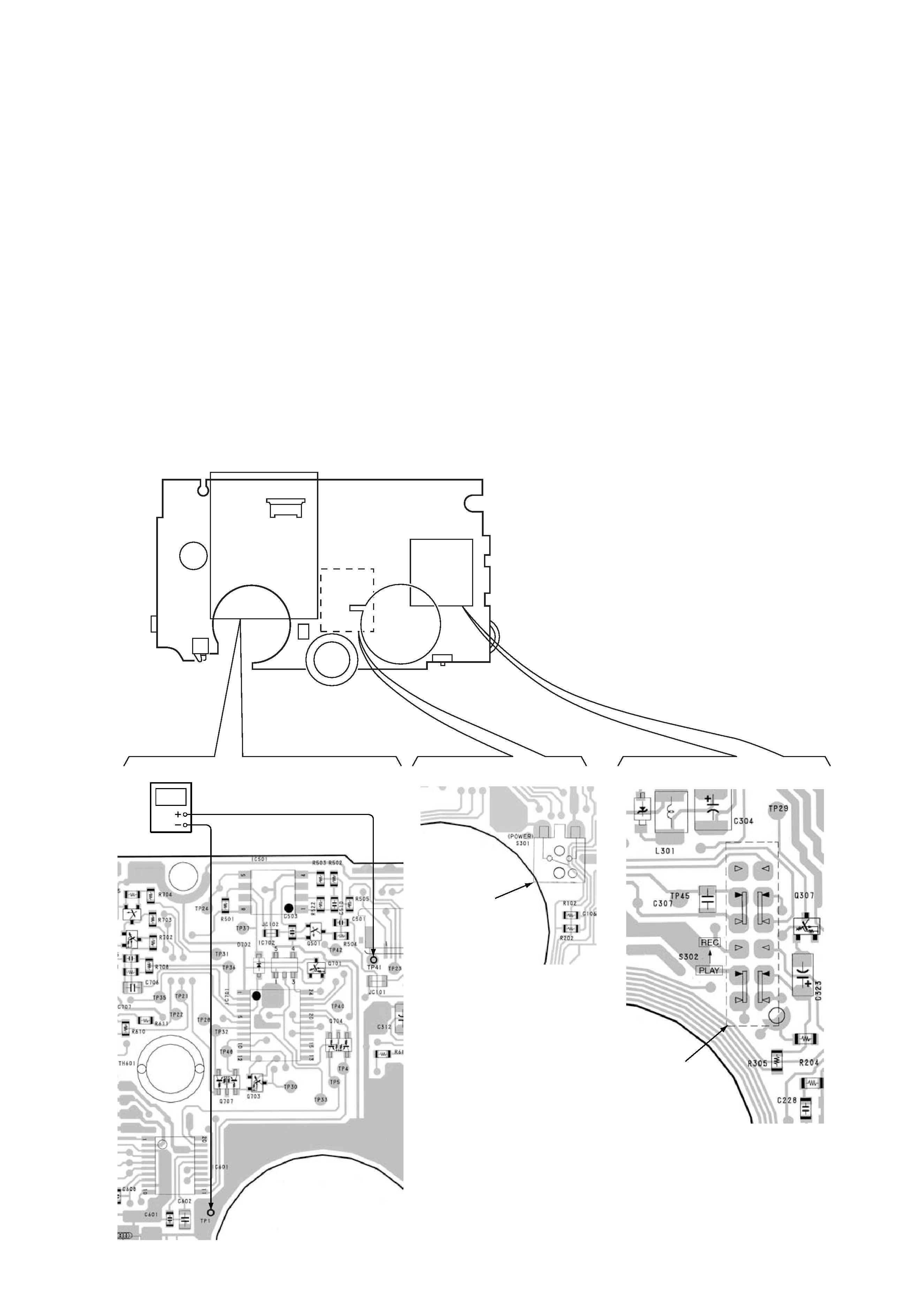
PULSE
10Hz 1.6V (4.5dB)
Oscillator
(Side B)
(Side A)
(Side A)
TP41
TP1
S301
S302
SECTION 1
SERVICE NOTE
The TCS-60DV detects rotation of both the supply and take-up side
reels using the PH701 (photo reflector).
Because the PH701 is
mounted on the Main board, auto stop is activated and reel rotation
cannot be detected when the Main board is removed. To check the
operation of mechanism deck and voltage without the Main board,
follow the procedure as described below.
How to remove the Main board (opening the Main board)
1) Refer to page 5 "3. Disassembly".
How to enter the fast forward/rewind modes
1) Input the square wave to the TP41. (Refer to the illustration
below.)
2) Press the fast forward/rewind keys.
3) Turn on the S301.
How to enter the playback mode
1) Input the square wave to the TP41. (Refer to the illustration
below.)
2) Press the playback key.
3) Set the S302 to the PLAY.
4) Turn on the S301.
How to enter the record mode
1) Input the square wave to the TP41. (Refer to the illustration
below.)
2) Press the record key.
3) Set the S302 to the REC.
4) Turn on the S301.
-- 4 --
SECTION 2
GENERAL
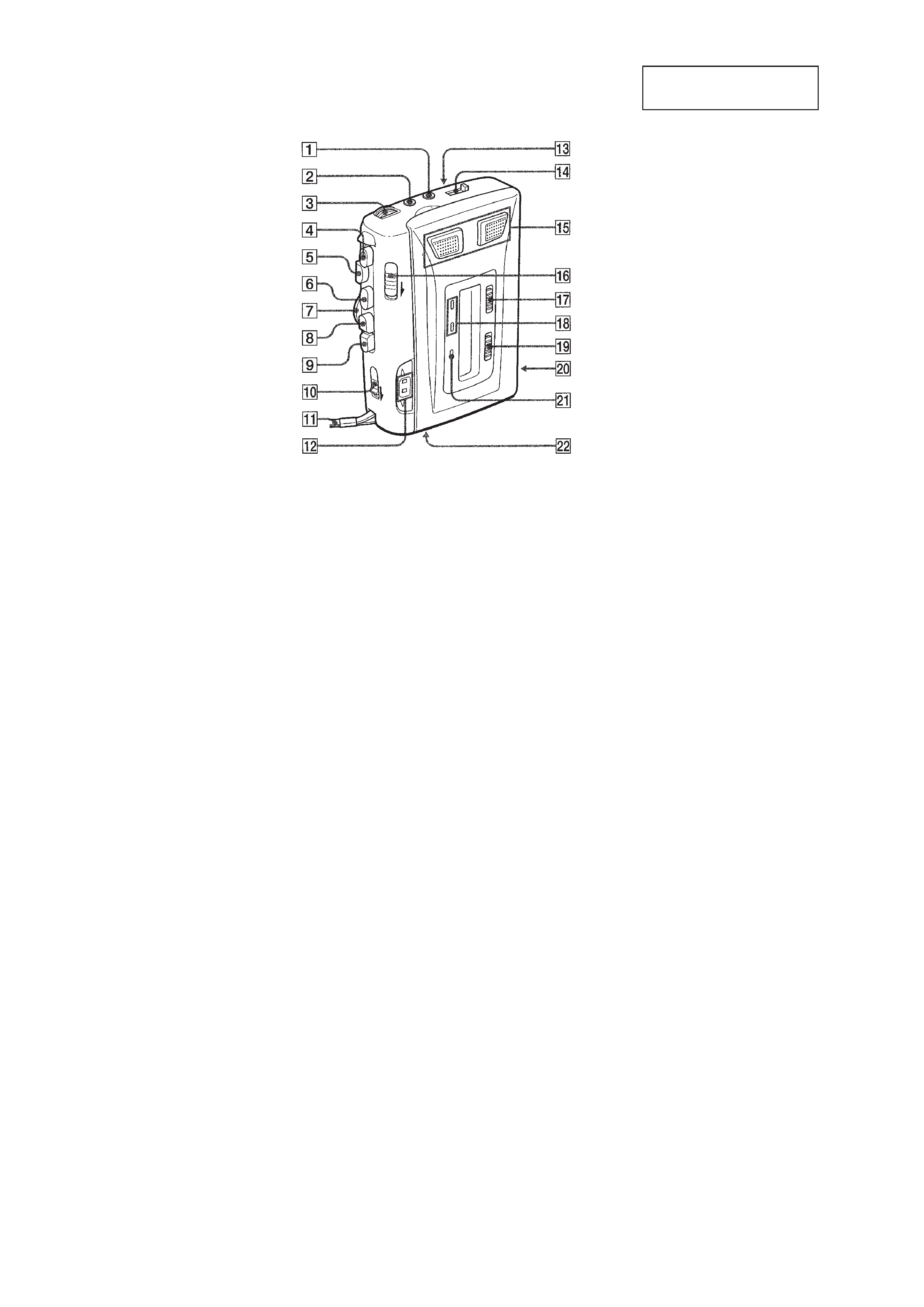
This section is extracted
from instruction manual.
!TM Tape direction indicators
!£ SPEAKER (REAR SIDE)
!¢ TAPE COUNTER switch
! Flat mic
!§ PAUSE c switch
!¶ REC TIME switch
!· BATT/REC indicator
!ª VOR switch
@º Battery compartment
@¡ i indicator
@TM DC IN 3V jack
1 2 Headphone jack
2 MIC (PULG IN POWER) jack
3 VOL knob
4 r REC button
5 p STOP button
6 PLAY button
7 SPEED CONTROL knob
8 REW/REVIEW button
9 FF/CUE button
0 DIR c switch
!¡ Hand strap
-- 5 --
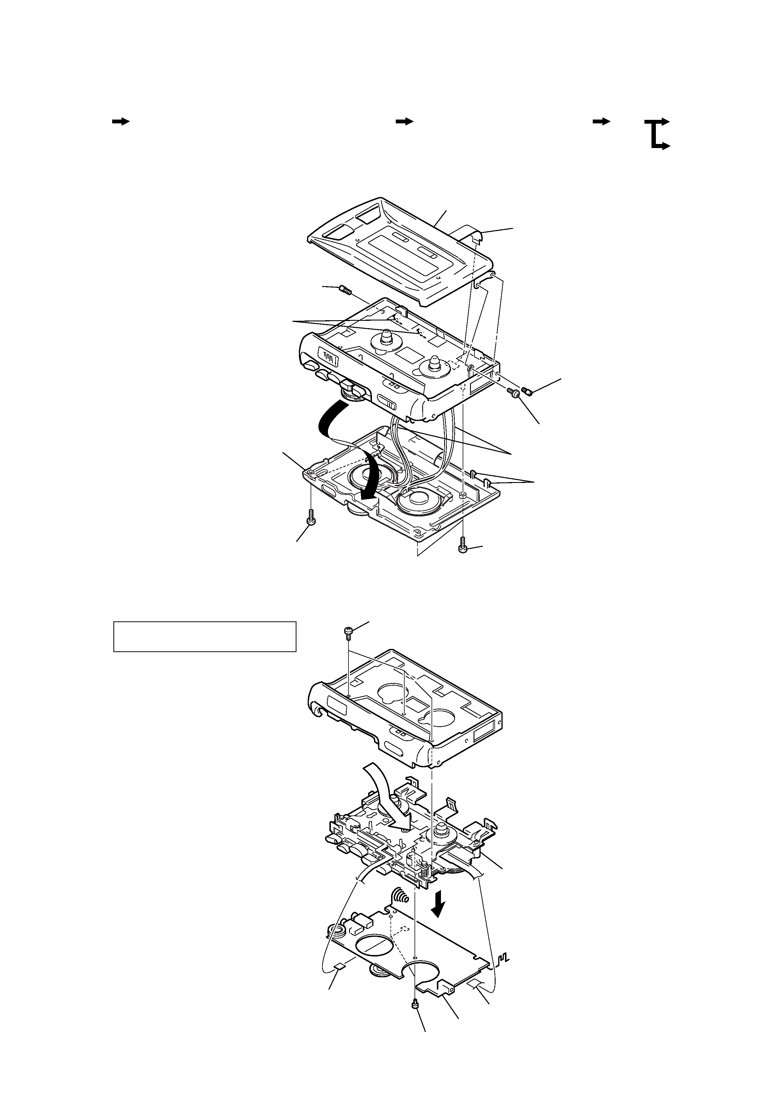
SECTION 3
DISASSEMBLY
Disassemble the unit in the order as shown below.
Note : Follow the disassembly procedure in the numerical order given.
3-1. "CABINET (REAR) ASSY", "LID SUB ASSY, CASSETTE"
Set
"Cabinet (rear) assy", "lid sub assy, cassette"
Main board, Mechanism deck
Belt
Head
Motor, dc
3-2. MAIN BOARD, MECHANISM DECK
1 Two screws(+B1.7
× 9)
2 Two screws(+B1.7
× 9)
4 Remove speaker cable (4pcs)
5 PWB, LED Flexible
6 Shaft(A), stopper
7 Screw, ornamental
8 Screw, ornamental
9 Lid Sub Assy, Cassette
Claws
3 Remove the Cabinet (rear) assy
in the direction of the allow
Claws
5 PC board, Motor flexible
1 Three screws(IB LOCK)
8 Mechanism deck
6 PC board, Head flexible
3 Two screws(M1.4), Toothed lock
7 MAIN board
2
4
NOTE: For attaching the Main board,
refer to the next page.