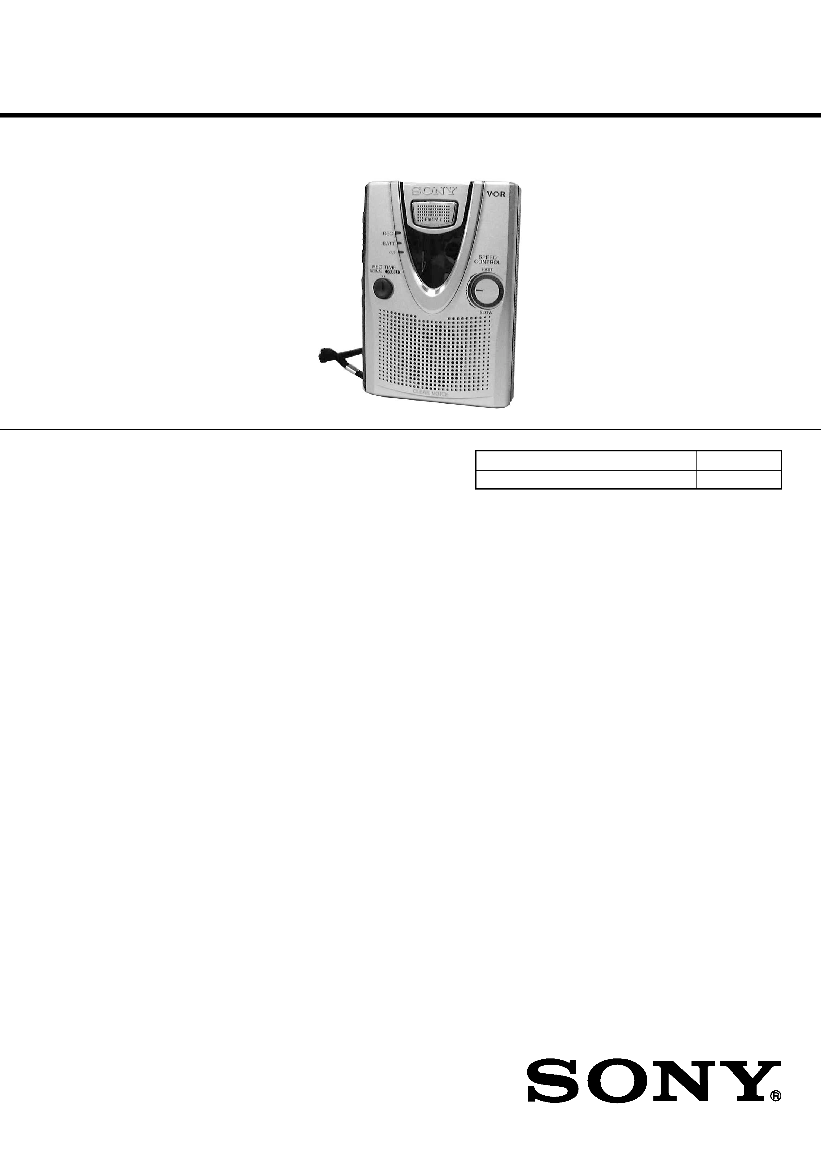
SERVICE MANUAL
CASSETTE-CORDER
E Model
Chinese Model
Tourist Model
Model Name Using Similar Mechanism
New
Tape Transport Mechanism Type
MT-400-175
SPECIFICATIONS
TCM-400DV
Ver 1.0 2001.10
9-873-336-01
2001J0200-1
© 2001. 10
Sony Corporation
Personal Audio Company
Published by Sony Engineering Corporation
Recording system
2-track 1 channel monaural
Tape speed
4.8 cm/s or 2.4 cm/s
Frequency range
250 - 6 300 Hz using nomal (TYPE
I) cassette (with REC TIME switch
at "NORMAL")
Speaker
Approx. 3.6 cm (1 7 /
16 in.) dia.
Power output
250 mW (at 10 % harmonic
distortion)
Input
Microphone input jack (minijack)
sensitivity 0.2 mV for 3 k
or
lower impedance microphone
Output
Earphone jack (minijack) for 8 -300
earphone
Variable range of the tape speed
From approx. +30% to 15% (with
REC TIME switch at "NORMAL")
Power requirements
3 V DC batteries R6 (AA) x 2/
External DC 3 V power sources
Dimensions (w/h/d) (incl. projecting parts and controls)
Approx. 86.7 x 114.4 x 35.4 mm
(3 1 /
2 x 4
5 /
8 x 1
7 /
16 in.)
Mass
Approx. 160 g (5.7 oz.) (main unit
only)
Design and specifications are subject to change without notice.
TCM-400DV
2
TABLE OF CONTENTS
1.
GENERAL ................................................................... 2
2.
DISASSEMBLY ......................................................... 3
3.
MECHANICAL ADJUSTMENTS ....................... 5
4.
ELECTRICAL ADJUSTMENTS ......................... 6
5.
DIAGRAMS
5-1. Block Diagrams ......................................................
7
5-2. Printed Wiring Board MAIN Board .................
8
5-3. Schematic Diagram ................................................
9
5-4. Printed Wiring Board LED Board .................... 10
5-5. IC BLOCK DIAGRAMS ....................................... 10
6.
EXPLODED VIEWS ................................................ 11
7.
ELECTRICAL PARTS LIST ............................... 15
Flexible Circuit Board Repairing
· Keep the temperature of the soldering iron around 270 °C dur-
ing repairing.
· Do not touch the soldering iron on the same conductor of the
circuit board (within 3 times).
· Be careful not to apply force on the conductor when soldering
or unsoldering.
Notes on chip component replacement
· Never reuse a disconnected chip component.
· Notice that the minus side of a tantalum capacitor may be dam-
aged by heat.
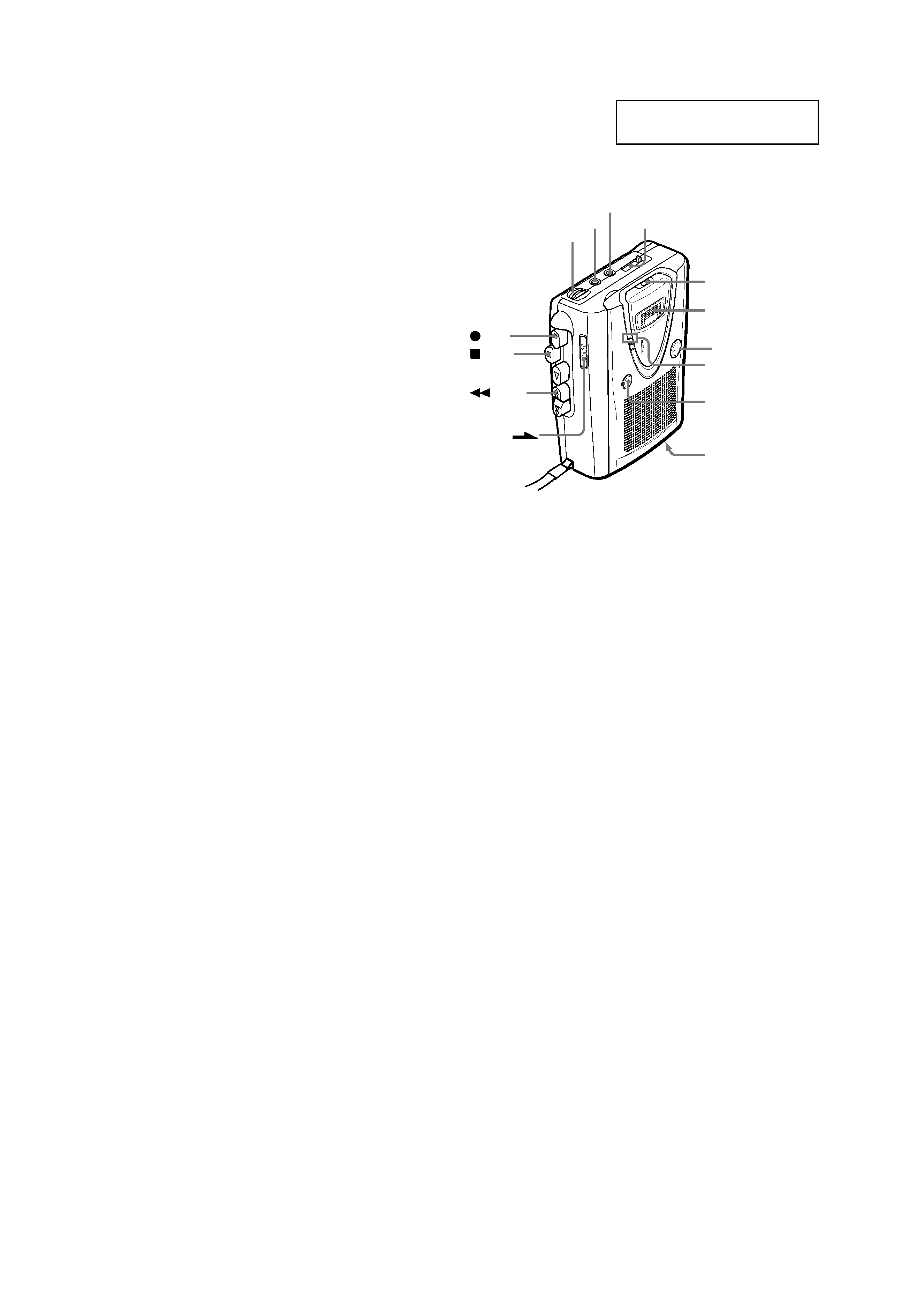
SECTION 1
GENERAL
This section is extracted from
instruction manual.
MIC
VOL
TAPE COUNTER
EAR
VOR
REC TIME
REC
DC IN 3V
REW/
REVIEW
STOP
PAUSE
REC
Flatmic
SPEED CONTROL
TCM-400DV
3
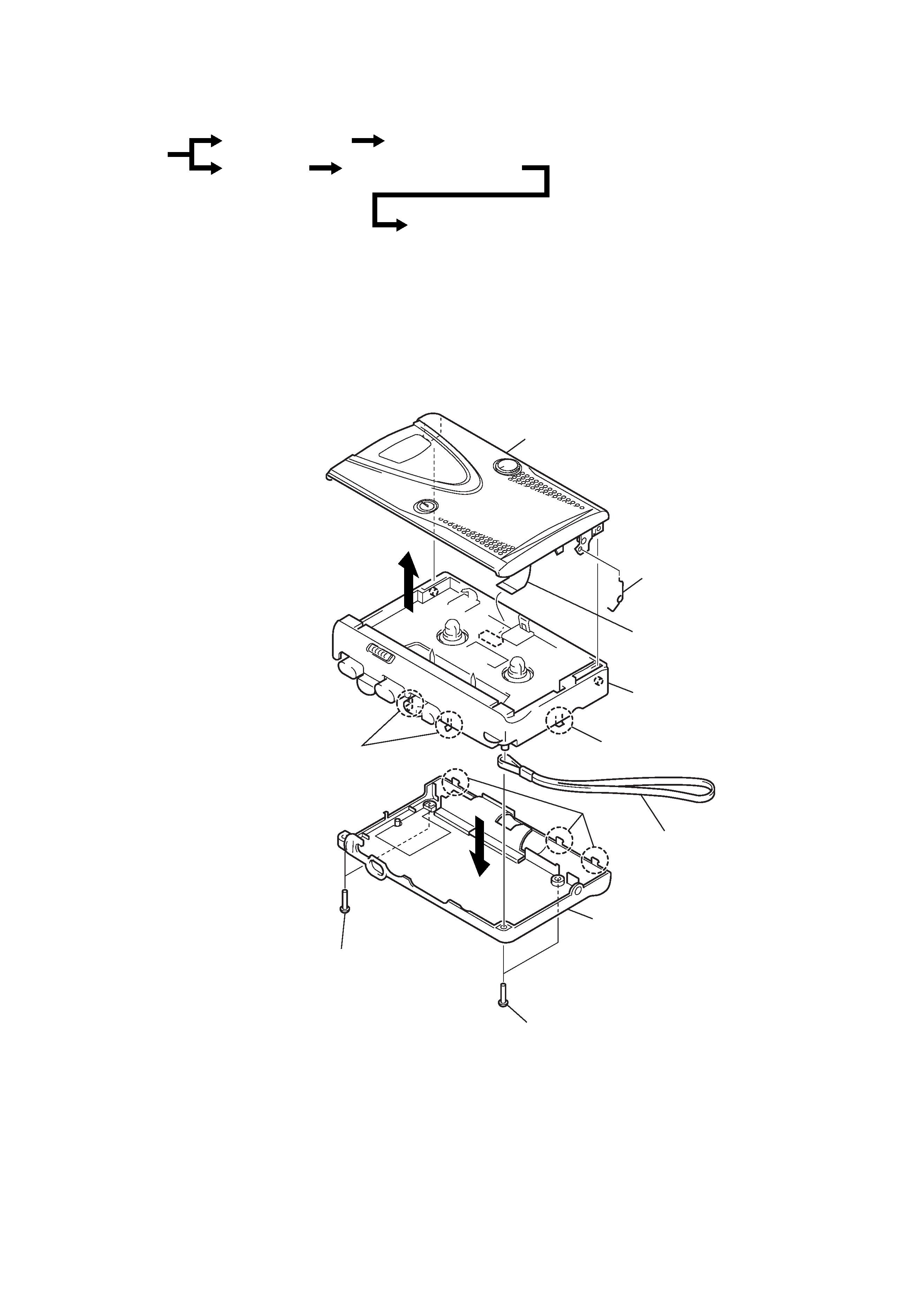
2-1.CABINET (REAR), CASSETTE HOLDER ASSY
Note: Follow the disassembly procedure in the numerical order given.
SECTION 2
DISASSEMBLY
· This set can be disassembled in the order shown below.
Cassette holder ASSY
Spring (cassette)
7
Claw
2
Claws
2
Strap, hand
4
3
6
Claws
2
Screws (B1.7X9)
1
Screws (B1.7X9)
1
Cabinet (front)
Cabinet (rear)
Flexible board (CN901)
5
Cassette holdr ASSY
LED board
Belt (cap), belt (pulley), M901 (capstan/reel motor), HRP901 (REC/PB head),
HE901 (erase head)
Set
Cabinet(rear)
MAIN Board,Mechanism Deck
TCM-400DV
4
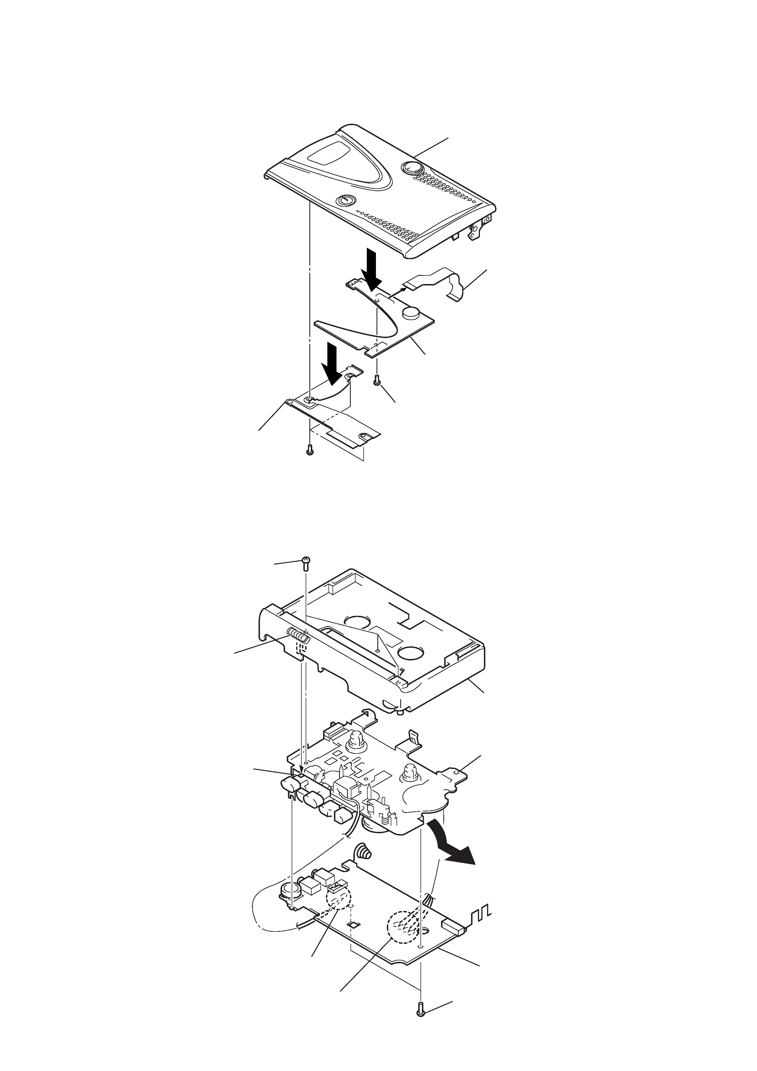
2-3. MAIN BOARD, MECHANISM DECK
Cabinet (front)
Mechanism deck
Main board
4
6
Screws (M1.4)
3
Screws (IB lock)
5
Remove solder
(four places)
2
Remove solder
(two places)
Lever (pause)
Knob (pause)
Note:
To install, position the Knob
(pause) and the lever (pause)
respectively.
1
2-2. LED BOARD
Cassette holder Assy
Screw(1.7)
3
LED board
Flexible board
5
Screws(1.7)
Freame
(cassette holder)
1
2
4
TCM-400DV
5
SECTION 3
MECHANICAL ADJUSTMENTS
Tape Tension Measurement
1. Clean the following parts with a denatured-alcohol-moistened
swab:
record/playback head
pinch roller
erase head
rubber belt
capstan
2. Demagnetize the record/playback head with a head demagne-
tizer. (Do not bring the head demagnetizer close to the erase
head.)
3. Do not use a magnetized screwdriver for the adjustments.
4. After the adjustments, apply suitable locking compound to the
parts adjusted.
5. The adjustments should be performed with the rated power
supply voltage (2.5 V) unless otherwise noted.
Mode
Torque Meter
Meter Reading
1.97 3.92mN·m
FWD
(20 40 g·cm)
CQ-102C
(0.28 0.55 oz·inch)
0.05 0.49 mN·m
Forward Back
(0.5 5 g·cm)
Tension
(0.007 0.069 oz·inch)
FF, REW
CQ-201B
more than 4.91 mN·m
(more than 50 g·cm)
(more than 0.69 oz·inch)
Mode
Tension Meter
Meter Reading
FWD
CQ-403A
more than 50 g
(more than 1.76 oz)
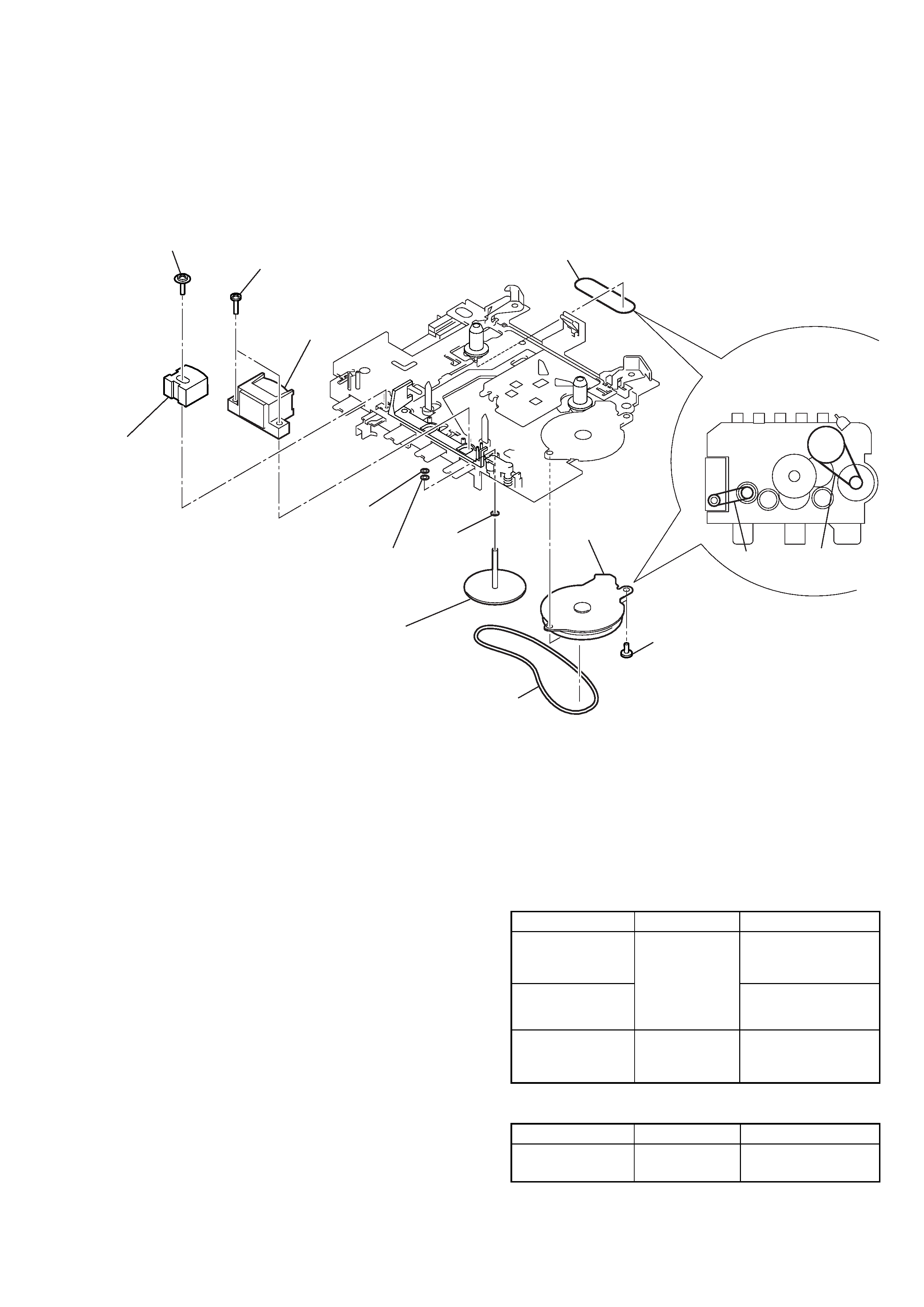
2-4. BELT (CAP), BELT (PULLEY), M901 (CAPSTAN/REEL MOTOR),
HRP901 (REC/PB HEAD), HE901 (ERASE HEAD)
HRP901
(REC/PB head)
Attaching belt (CAP)
and belt (pulley)
z
Belt (CAP)
Belt (CAP)
Belt (pulley)
Belt (pulley)
Screws (M1.4)
3
M901
(Capstan/reel
motor)
4
1
8
7Fly ASSY,
capstan
Washer
6Washer
5
0
qs
9
2
Washer
(stopper N)
Screws
HE901
(Erase head)
qa
Screw
Torque Measurement