SERVICE MANUAL
CASSETTE-CORDER
US Model
Canadian Model
AEP Model
E Model
Model Name Using Similar Mechanism
NEW
Tape Transport Mechanism Type
MT-323-118
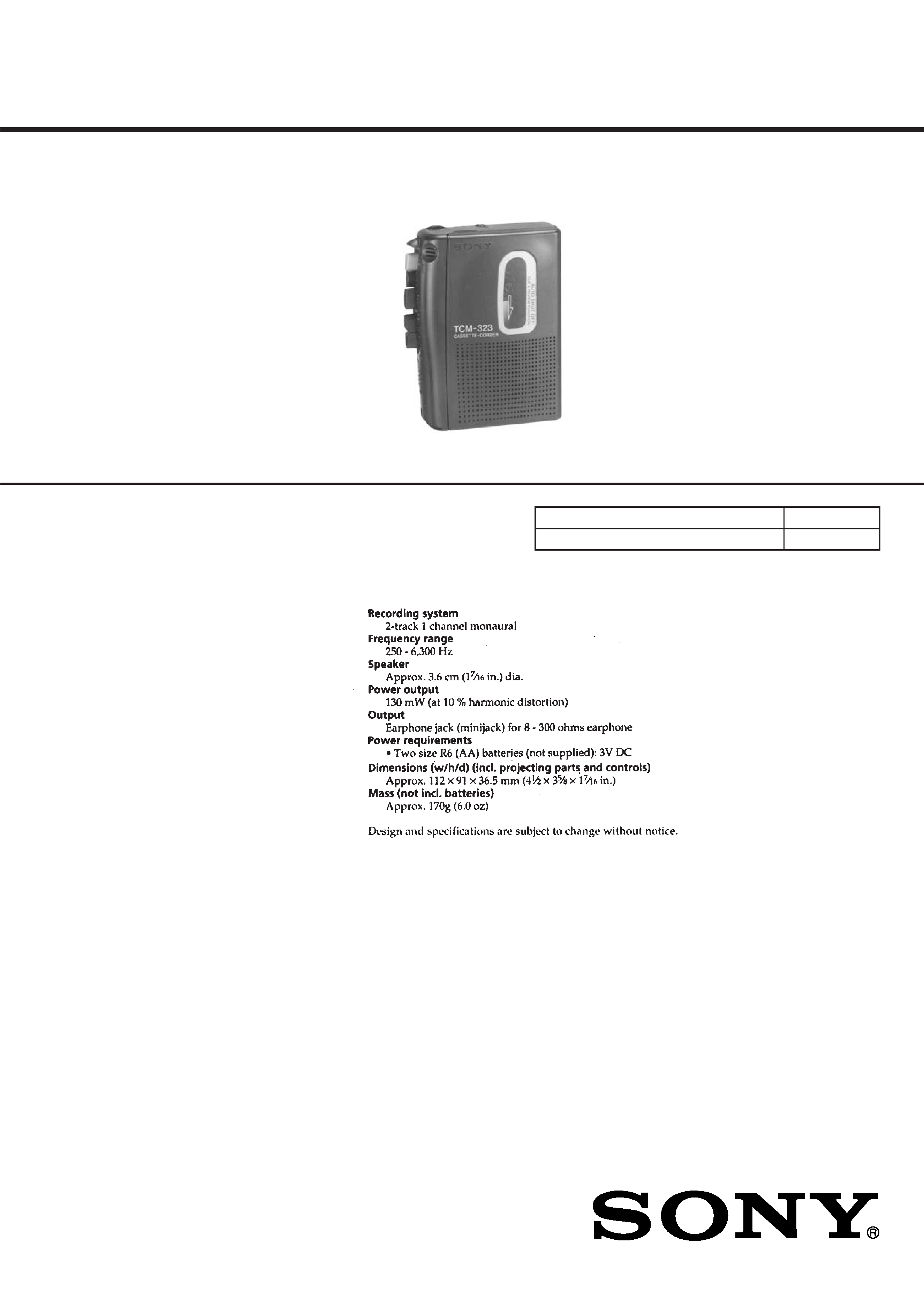
SPECIFICATIONS
TCM-323
Ver 1.2 2004.03
9-923-304-12
Sony Corporation
2004C05-1
Personal Audio Company
© 2004.03
Published by Sony Engineering Corporation
2
In this set, the S102 (power) detects REC/PLAYBACK on.
It is mounted on the MAIN board, and therefore the REC/PLAY-
BACK on cannot be detected with the MAIN board removed.
When making an operation check and voltage check of mechani-
cal deck with the MAIN board removed, fix the S102 at turn on.
SECTION 1
SERVICING NOTES
Notes on chip component replacement
· Never reuse a disconnected chip component.
· Notice that the minus side of a tantalum capacitor may be dam-
aged by heat.
[MAIN BOARD] (Conductor Side)
IC101
IC102
IC601
TABLE OF CONTENTS
1.
SERVICING NOTES ............................................... 2
2.
GENERAL .................................................................. 3
3.
DISASSEMBLY ......................................................... 4
4.
MECHANICAL ADJUSTMENTS ....................... 7
5.
ELECTRICAL ADJUSTMENTS ......................... 8
6.
DIAGRAMS
6-1. Block Diagram ................................................................ 9
6-2. Schematic Diagram ......................................................... 11
6-3. Printed Wiring Board ...................................................... 13
7.
EXPLODED VIEWS ................................................ 14
8.
ELECTRICAL PARTS LIST ............................... 17
3
SECTION 2
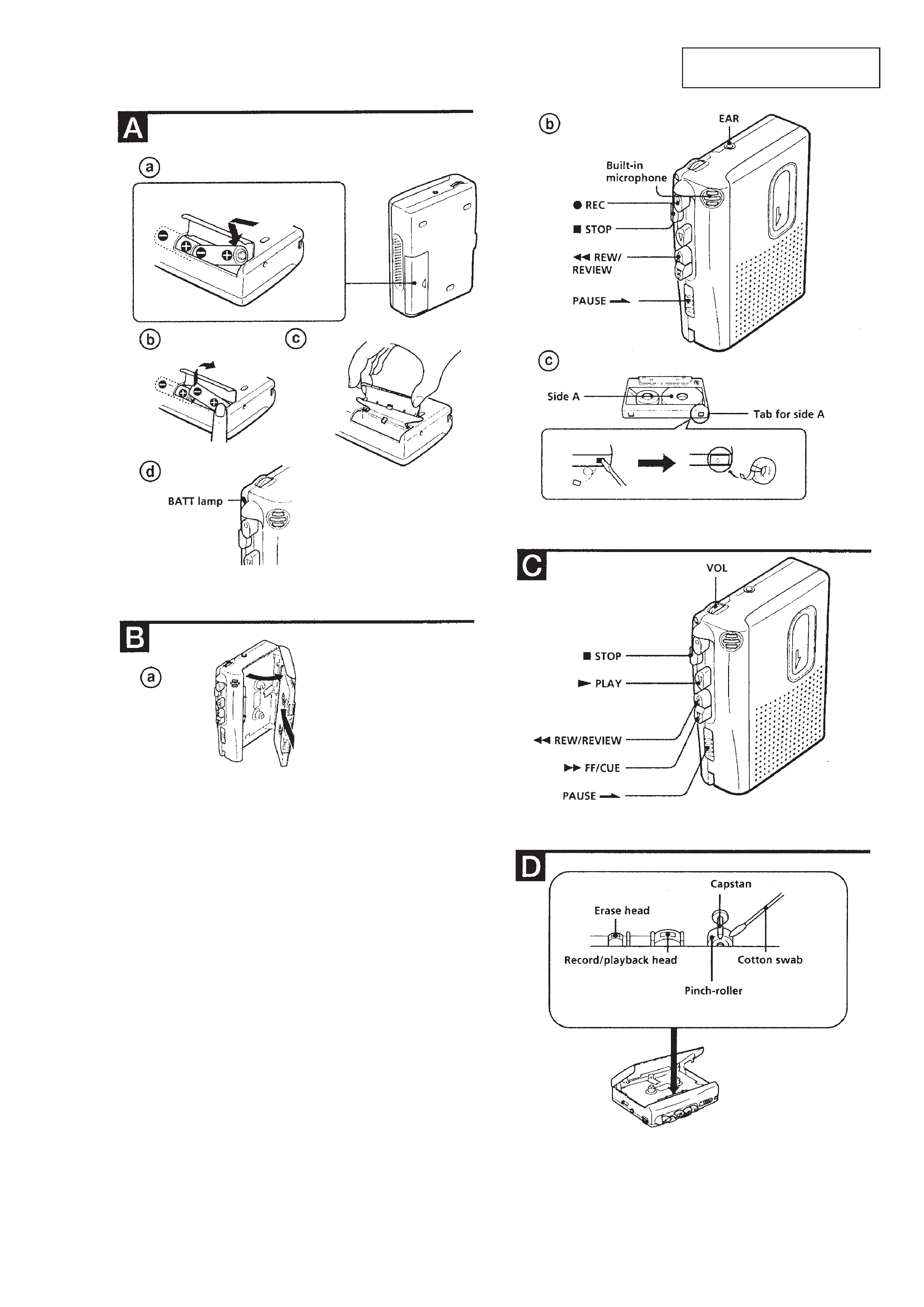
GENERAL
This section is extracted from
instruction manual.
4
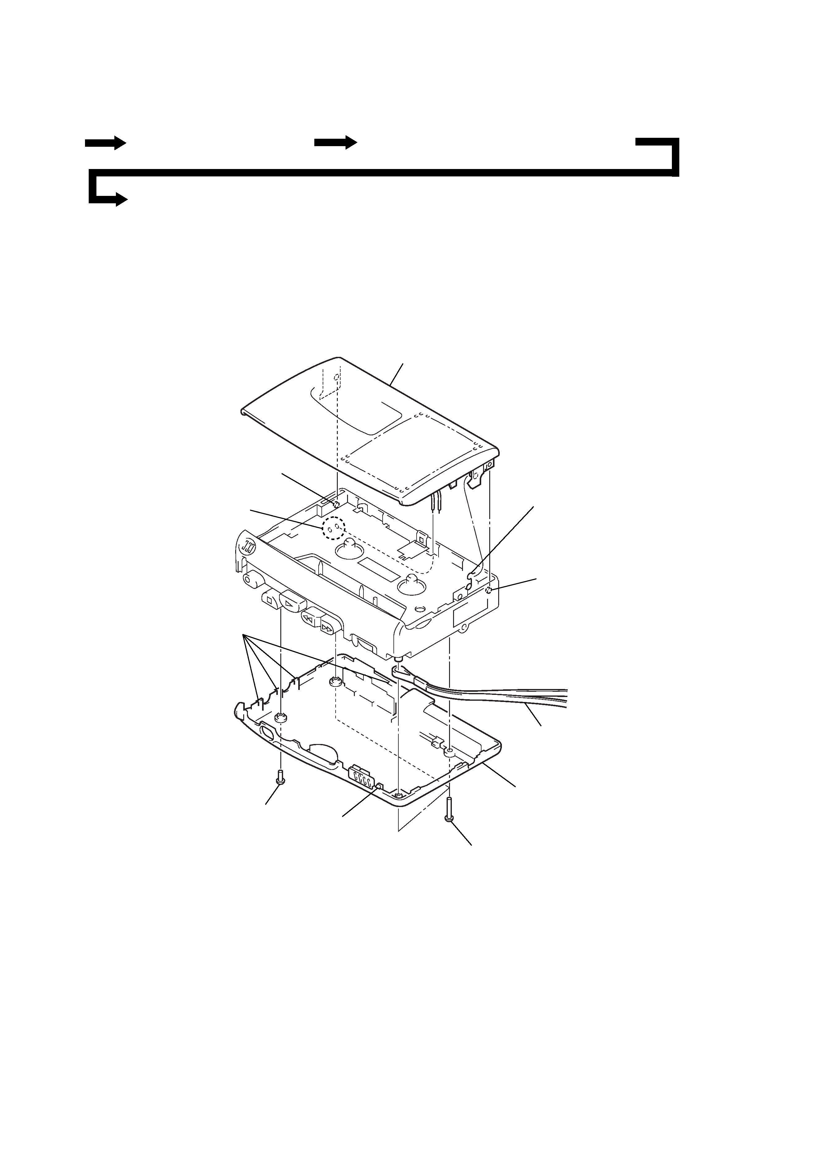
CABINET (REAR), CASSETTE LID
Note: Follow the disassembly procedure in the numerical order given.
SECTION 3
DISASSEMBLY
· This set can be disassembled in the order shown below.
9 cassette lid
8 cassette spring
5 strap
3 claw
3 four claws
2 screw
(IB lock)
4 cabinet (rear)
1 three screws
(B1.7
× 9)
7 boss
7 boss
6 Remove the two solders
speaker cords.
SET
CABINET (REAR), CASSETTE LID
MAIN BOARD, MECHANISM DECK (MT-323-118)
BELT
5
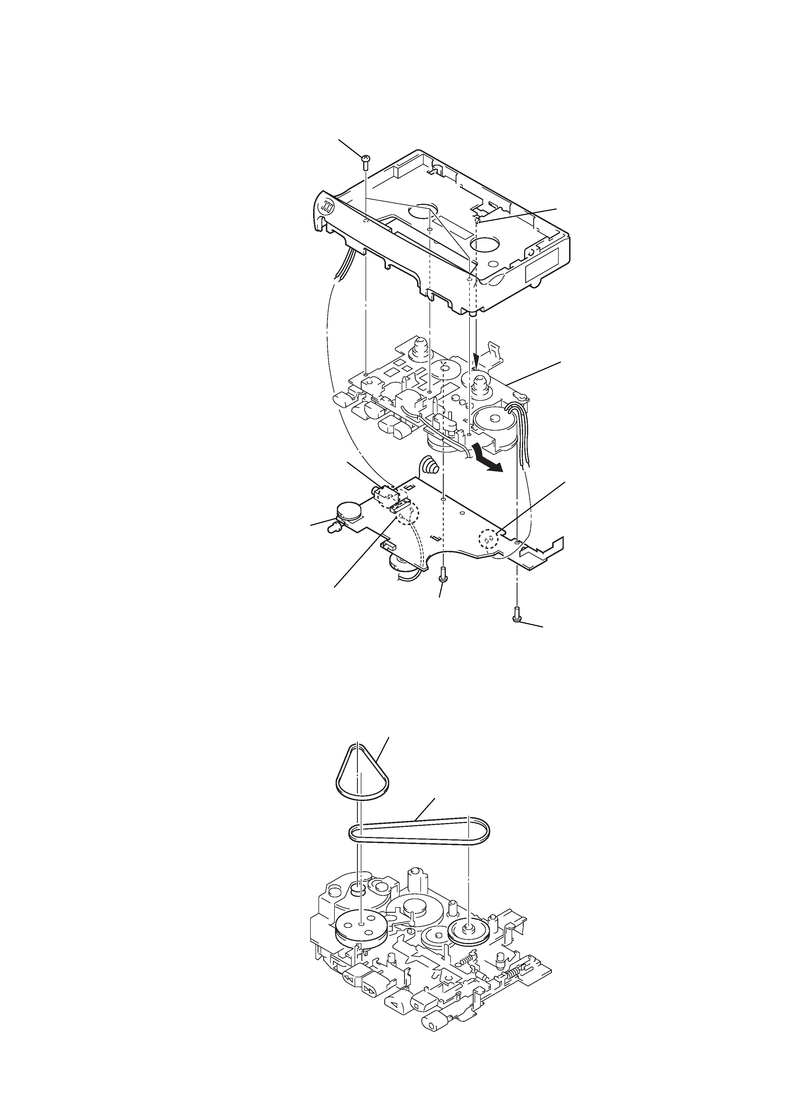
MAIN BOARD, MECHANISM DECK (MT-323-118)
BELT
6 claw
2 screw
(1.7)
3 screw
(M1.4)
4 MAIN board
7 mechanism deck
(MT-323-118)
5 three screws
(IB lock)
1 Remove the two solders
electret condenser microphone
(MIC901).
1 Remove the two solders
magnetic head (HRP901).
1 Remove the two solders
motor (M901).
1 belt (capstan)
2 belt (FR)