3-866-165-12(1)
Multichannel
Pre Amplifier
© 1999 by Sony Corporation
TA-P9000ES
Operating Instructions
Mode d'emploi
GB
FR
2GB
WARNING
To prevent fire or shock
hazard, do not expose the
unit to rain or moisture.
Do not install the
appliance in a confined
space, such as a bookcase
or built-in cabinet.
For the customers in United States
This symbol is intended to alert the user to
the presence of uninsulated "dangerous
voltage" within the product's enclosure
that may be of sufficient magnitude to
constitute a risk of electric shock to
persons.
This symbol is intended to alert the user to
the presence of important operating and
maintenance (servicing) instructions in the
literature accompanying the appliance.
Owner's Record
The model and serial numbers are located
on the rear of the unit. Record the serial
number in the space provided below.
Refer to them whenever you call upon
your Sony dealer regarding this product.
Model No. TA-P9000ES
Serial No.
For the customers in Canada
CAUTION
TO PREVENT ELECTRIC SHOCK, DO
NOT USE THIS POLARIZED AC PLUG
WITH AN EXTENSION CORD,
RECEPTACLE OR OTHER OUTLET
UNLESS THE BLADES CAN BE FULLY
INSERTED TO PREVENT BLADE
EXPOSURE.
INFORMATION
This equipment has been tested and found
to comply with the limits for a Class B
digital device, pursuant to Part 15 of the
FCC Rules.
These limits are designed to provide
reasonable protection against harmful
interference in a residential installation.
This equipment generates, uses, and can
radiate radio frequency energy and, if not
installed and used in accordance with the
instructions, may cause harmful
interference to radio communications.
However, there is no guarantee that
interference will not occur in a particular
installation. If this equipment does cause
harmful interference to radio or television
reception, which can be determined by
turning the equipment off and on, the user
is encouraged to try to correct the
interference by one or more of the
following measures:
Reorient or relocate the receiving
antenna.
Increase the separation between the
equipment and pre amplifier.
Connect the equipment into an outlet on
a circuit different from that to which the
pre amplifier is connected.
Consult the dealer or an experienced
radio/TV technician for help.
CAUTION
You are cautioned that any changes or
modification not expressly approved in
this manual could void your authority to
operate this equipment.
Note to CATV system installer:
This reminder is provided to call CATV
system installer's attention to Article 820-
40 of the NEC that provides guidelines for
proper grounding and, in particular,
specifies that the cable ground shall be
connected to the grounding system of the
building, as close to the point of cable
entry as practical.

3GB
TABLE OF CONTENTS
Hooking Up the Components
4
Unpacking 4
Control Amplifier Hookups 5
Power Amplifier Hookups 6
Additional Audio Hookups 7
Turning the TA-N9000ES On/Off From This Unit 8
Power Connections 8
Location of Parts and Basic
Operations
10
Front Panel Parts Description 10
Rear Panel Parts Description 12
Additional Information
13
Precautions 13
Troubleshooting 14
Specifications 16
GB
About This Manual
The instructions in this manual are for model
TA-P9000ES. Check your model number by looking at the
lower right corner of the front panel. In this manual, the
European model is used for illustration purposes unless
stated otherwise. Any difference in operation is clearly
indicated in the text, for example, "USA/Canada only."
Conventions
· The instructions in this manual describe the controls on
the pre amplifier. You can also use the controls on the
supplied remote if they have the same or similar names
as those on the pre amplifier. For details on the use of
your remote, refer to the separate operating instructions
supplied with the remote.
· The following icon is used in this manual:
z Indicates hints and tips for making the task easier.
4GB
Hooking Up
the
Components
This chapter describes how to connect
a Sony TA-E9000ES control amplifier,
a Sony TA-N9000ES power amplifier,
and your other audio components to
the pre amplifier. Be sure to read this
section before making any
connections.
Unpacking
Check that you received the following items with the unit:
· Audio cord (3)
· Remote commander RM-P9000 (remote) (1)
· R6 (size-AA) batteries (2)
· Control A1 connecting cord (1)
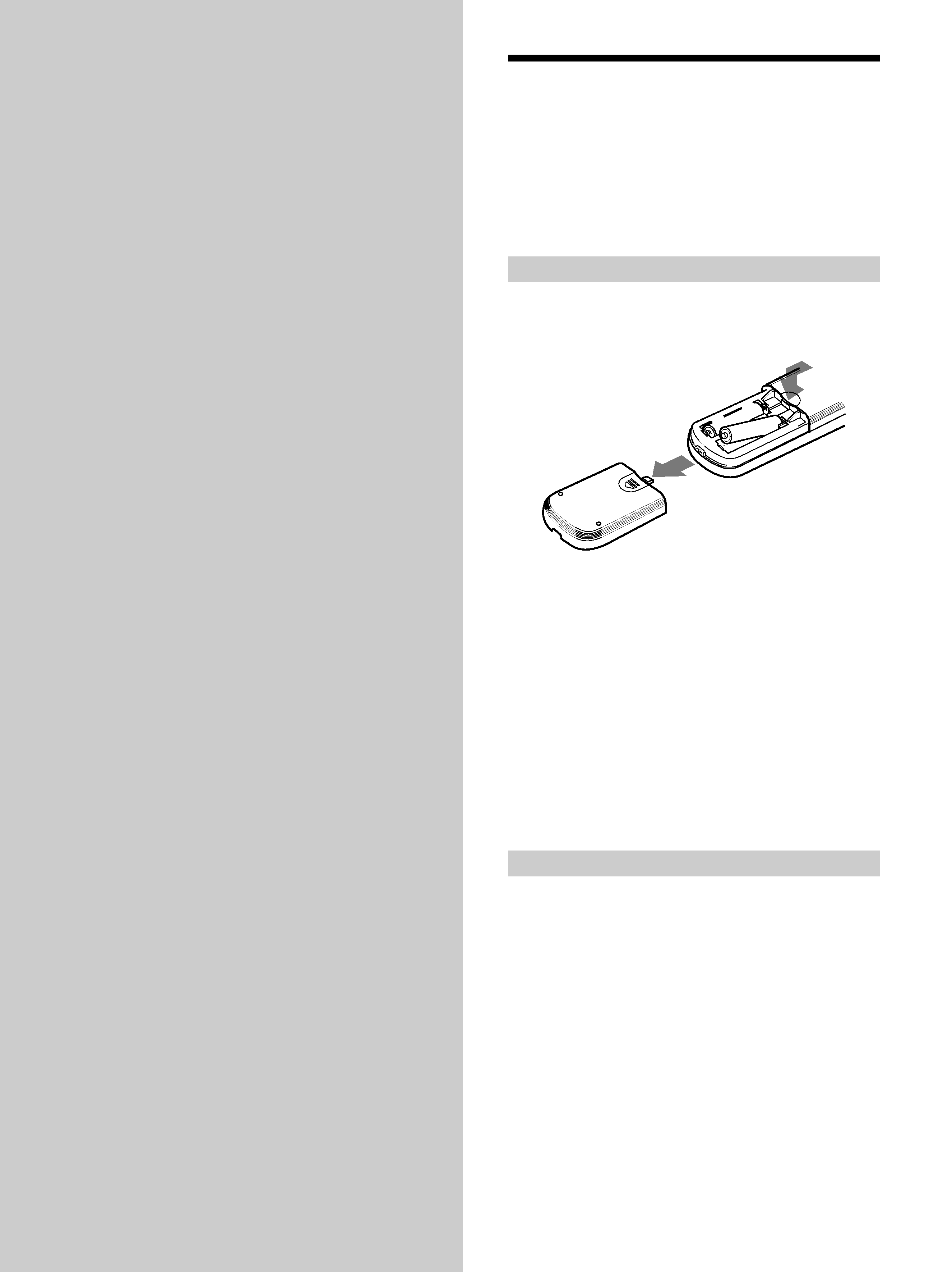
Inserting batteries into the remote
Insert two size-AA (R6) batteries with the + and
properly oriented in the battery compartment. When
using the remote, point it at the remote sensor g on the
pre amplifier.
z When to replace batteries
Under normal conditions, the batteries should last for about 6
months. When the remote no longer operates the pre amplifier,
replace all batteries with new ones.
Notes
· Do not leave the remote in an extremely hot or humid place.
· Do not use new batteries with old ones.
· Do not mix battery types.
· Do not expose the remote sensor to direct sunlight or lighting
apparatuses. Doing so may cause a malfunction.
· If you don't use the remote for an extended period of time,
remove the batteries to avoid possible damage from battery
leakage and corrosion.
Before you get started
· Turn off the power to all components before making
any connections.
· Do not connect the AC power cords until all of the
connections are completed.
· Be sure to make connections firmly to avoid hum and
noise.
· When connecting an audio cord, be sure to match the
color-coded pins to the appropriate jacks on the
components: white (left) to white; and red (right) to
red.
· When connecting the woofer or center channel, you can
use either the red or white pins on the audio cord.
}
]
}
]
5GB
Hooking
Up
the
Components
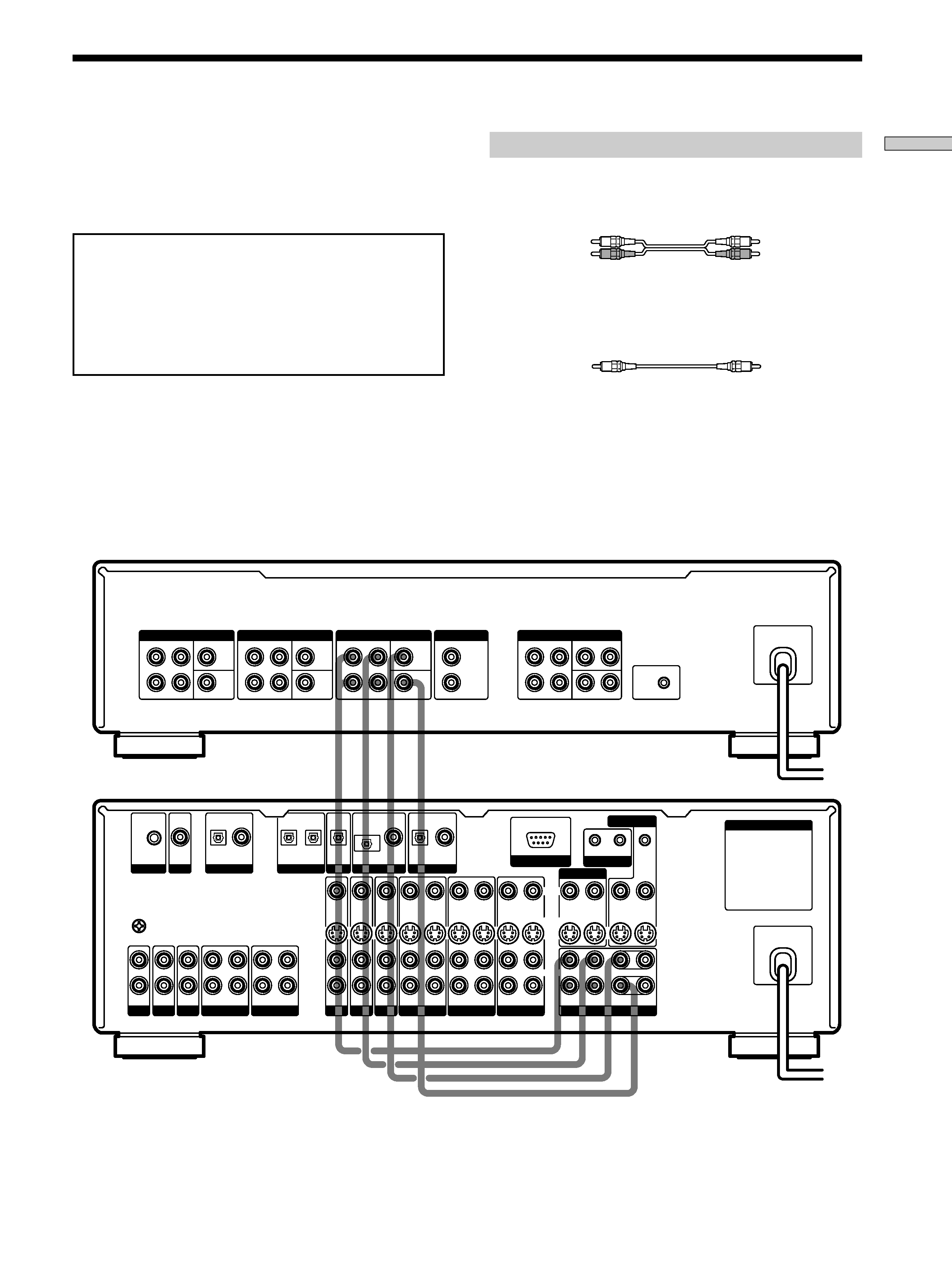
Control Amplifier Hookups
Connect the front, rear, center, and woofer pre out jacks on
your control amplifier (Sony TA-E9000ES etc.) to the pre
amplifier's BYPASS 5.1ch input jacks. For details, see the
operating instructions supplied with your control
amplifier.
To prevent damage to your speakers, do not connect
components whose volume cannot be controlled to the
BYPASS 5.1ch or BYPASS 2ch jacks.
Audio signals input to the BYPASS 5.1ch or BYPASS 2ch
jacks are not routed through this unit's MASTER
VOLUME control. They are output at the same level
they were input.
Required cords
Audio cords (not supplied)
When connecting a cord, be sure to match the color-coded pins to
the appropriate jacks on the components.
Monaural audio cords (not supplied)
For the BYPASS 5.1ch CENTER and BYPASS 5.1ch WOOFER
jacks.
Black
Black
z When making woofer and center channel connections
You can use one set of pins (e.g., red) on the audio cord (not
supplied) to connect the CENTER jacks and the other set (e.g.,
white) to connect the WOOFER jacks.
White (L)
White (L)
Red (R)
Red (R)
TA-P9000ES
TA-E9000ES etc.
AC OUTLET
PHONO TUNER
CD
MD/DAT
TAPE
DVD
TV
LD
VIDEO 3
VIDEO 2
VIDEO 1
PRE OUT
S-LINK
RS-232C
LD
DVD
TV
MD/DAT
CD
MONITOR
LD
ANALYZER
MIC IN
AC-3 RF
IN
OPTICAL
IN
COAXIAL
IN
OPTICAL
OUT
OPTICAL
IN
OPTICAL
IN
OPTICAL
IN
OPTICAL
IN
COAXIAL
IN
COAXIAL
IN
CTRL A1
CTRL S
IN
OUT
OUT
IN
OUT
IN
OUT
IN
OUT
IN
OUT
IN
IN
IN
IN
IN
IN
REC OUT
IN
REC OUT
IN
IN
IN
IN
REC OUT
IN
REC OUT
IN
REC OUT
IN
FRONT
REAR
WOOFER
CENTER
VIDEO
S-VIDEO
AUDIO
L
R
PROCESSOR
L
R
SIGNAL GND
y
PRE OUT
WOOFER
FRONT
REAR
CENTER
L
R
INPUT 1
WOOFER
FRONT
REAR
CENTER
L
R
INPUT 2
WOOFER
FRONT
REAR
CENTER
L
R
BYPASS 5.1ch
WOOFER
FRONT
REAR
CENTER
L
R
BYPASS 2ch
L
R
CTRL A1
TO POWER AMP