1
TA-N1
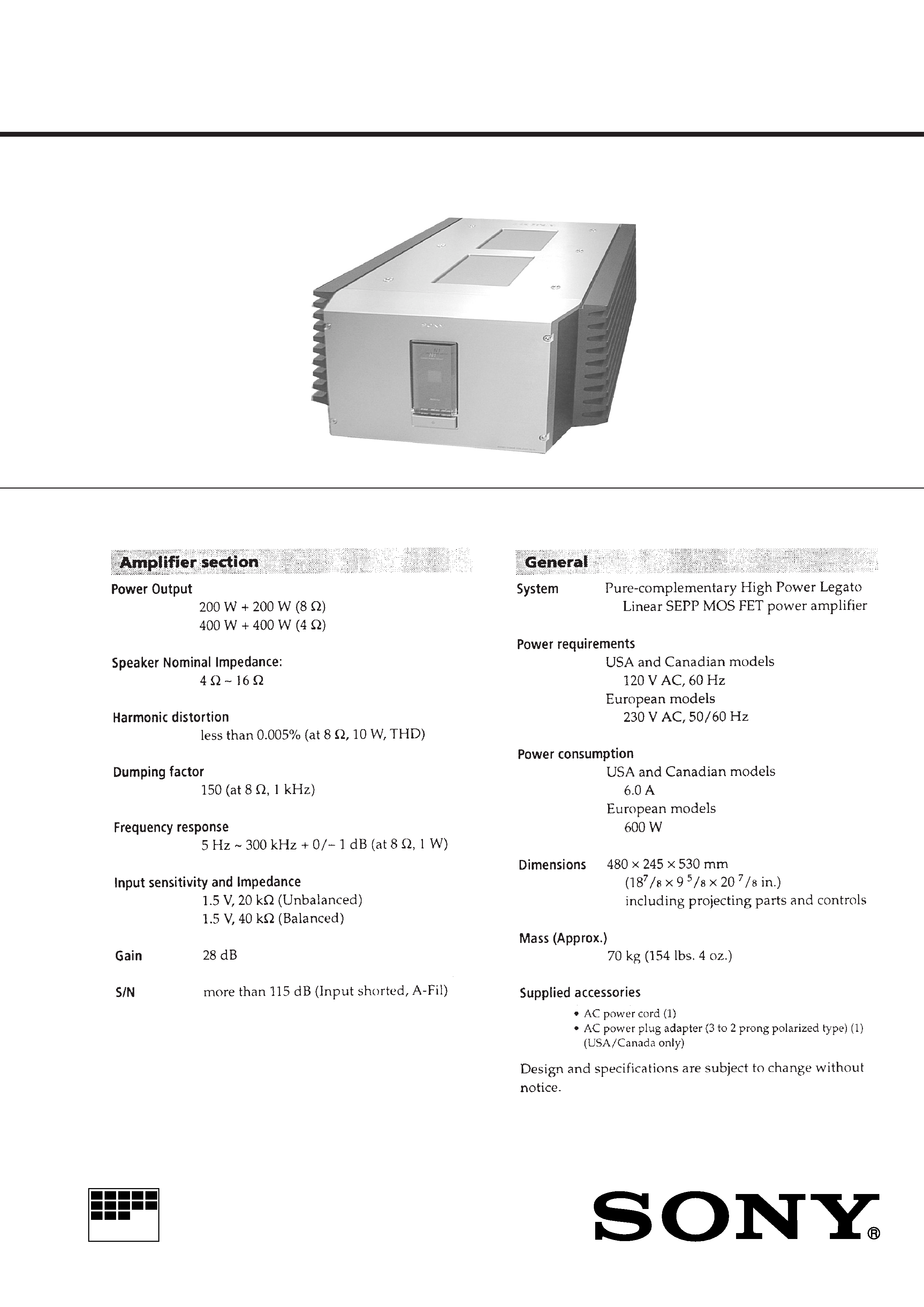
SPECIFICATIONS
STEREO POWER AMPLIFIER
SERVICE MANUAL
US Model
Canadian Model
AEP Model
UK Model
E Model
Australian Model
MICROFILM
2
TABLE OF CONTENTS
1. SERVICE NOTE ................................................................ 3
2. GENERAL ........................................................................... 5
3. ELECTRICAL ADJUSTMENT ..................................... 7
4. DIAGRAMS
4-1. Circuit Boards Location ........................................................ 7
4-2. Schematic Diagram Main L Section ............................... 8
4-3. Printed Wiring Board Main L Section ............................ 9
4-4. Schematic Diagram Main R Section ............................. 10
4-5. Printed Wiring Board Main R Section .......................... 11
4-6. Schematic Diagram Input Section ................................ 12
4-7. Printed Wiring Board Input Section .............................. 13
4-8. Schematic Diagram Power Section ............................... 14
4-9. Printed Wiring Board Power Section ............................ 15
5. EXPLODED VIEWS
5-1. Top and Back Panel Section ................................................ 16
5-2. Front Panel Section ............................................................. 16
5-3. Heat Sink Section ................................................................ 17
5-4. Bottom Plate and Frame Section ......................................... 18
6. ELECTRICAL PARTS LIST ................................... 19
SAFETY CHECK-OUT
After correcting the original service problem, perform the follow-
ing safety checks before releasing the set to the customer:
Check the antenna terminals, metal trim, "metallized" knobs, screws,
and all other exposed metal parts for AC leakage. Check leakage as
described below.
LEAKAGE
The AC leakage from any exposed metal part to earth Ground and
from all exposed metal parts to any exposed metal part having a
return to chassis, must not exceed 0.5 mA (500 microampers). Leak-
age current can be measured by any one of three methods.
1. A commercial leakage tester, such as the Simpson 229 or RCA
WT-540A. Follow the manufacturers' instructions to use these
instruments.
2. A battery-operated AC milliammeter. The Data Precision 245
digital multimeter is suitable for this job.
3. Measuring the voltage drop across a resistor by means of a VOM
or battery-operated AC voltmeter. The "limit" indication is 0.75
V, so analog meters must have an accurate low-voltage scale.
The Simpson 250 and Sanwa SH-63Trd are examples of a pas-
sive VOM that is suitable. Nearly all battery operated digital
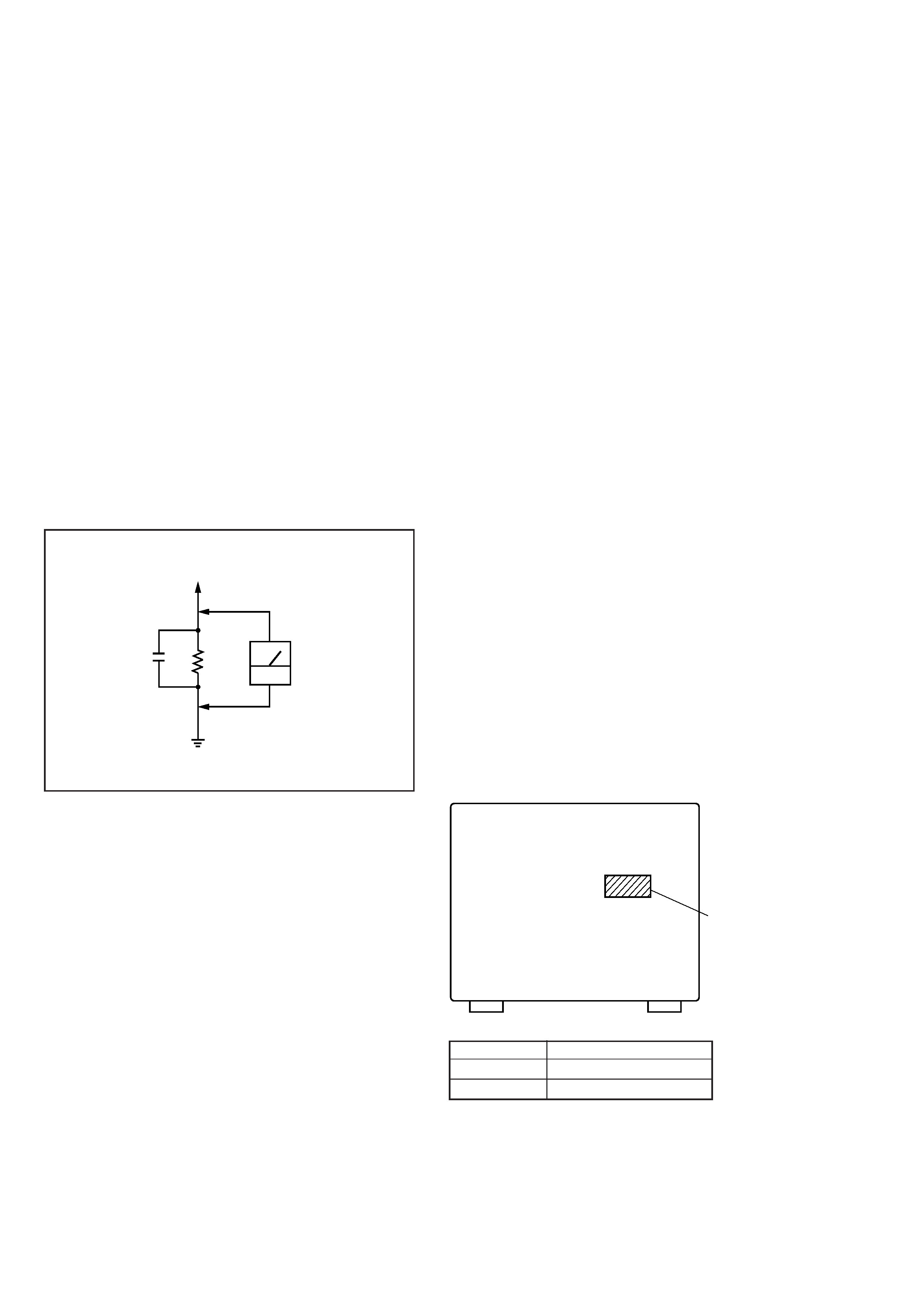
multimeters that have a 2V AC range are suitable. (See Fig. A)
Fig. A. Using an AC voltmeter to check AC leakage.
0.15
µF
To Exposed Metal
Parts on Set
1.5k
AC
voltmeter
(0.75V)
Earth Ground
SAFETY-RELATED COMPONENT WARNING !!
COMPONENTS IDENTIFIED BY MARK
! OR DOTTED LINE
WITH MARK
! ON THE SCHEMATIC DIAGRAMS AND IN
THE PARTS LIST ARE CRITICAL TO SAFE OPERATION.
REPLACE THESE COMPONENTS WITH SONY PARTS
WHOSE PART NUMBERS APPEAR AS SHOWN IN THIS
MANUAL OR IN SUPPLEMENTS PUBLISHED BY SONY.
ATTENTION AU COMPOSANT AYANT RAPPORT
À LA SÉCURITÉ!!
LES COMPOSANTS IDENTIFIÉS PAR UNE MARQUE
!SUR
LES DIAGRAMMES SCHÉMATIQUES ET LA LISTE DES
PIÈCES SONT CRITIQUES POUR LA SÉCURITÉ DE
FONCTIONNEMENT. NE REMPLACER CES COMPOSANTS
QUE PAR DES PIÈCES SONY DONT LES NUMÉROS
SONT DONNÉS DANS CE MANUEL OU DANS LES
SUPPLÉMENTS PUBLIÉS PAR SONY.
MODEL IDENTIFICATION
-- BACK PANEL --
PARTS No.
MODEL
4-217-757-1
US , CND
4-217-757-2
AEP, UK, E, AUS
·
Abbreviation
CND : Canadian model
AUS : Australian model
Parts No.
3
SECTION 1
SERVICE NOTE
EPT506
FPT558
CN554 (Red) 2P
CN654 (Red) 4P
CN201 (Red) 4P
CN751 (Red) 4P
CN852 (Red) 4P
CN702 (Black) 4P
CN701 (White) 4P
CN604 (White) 4P
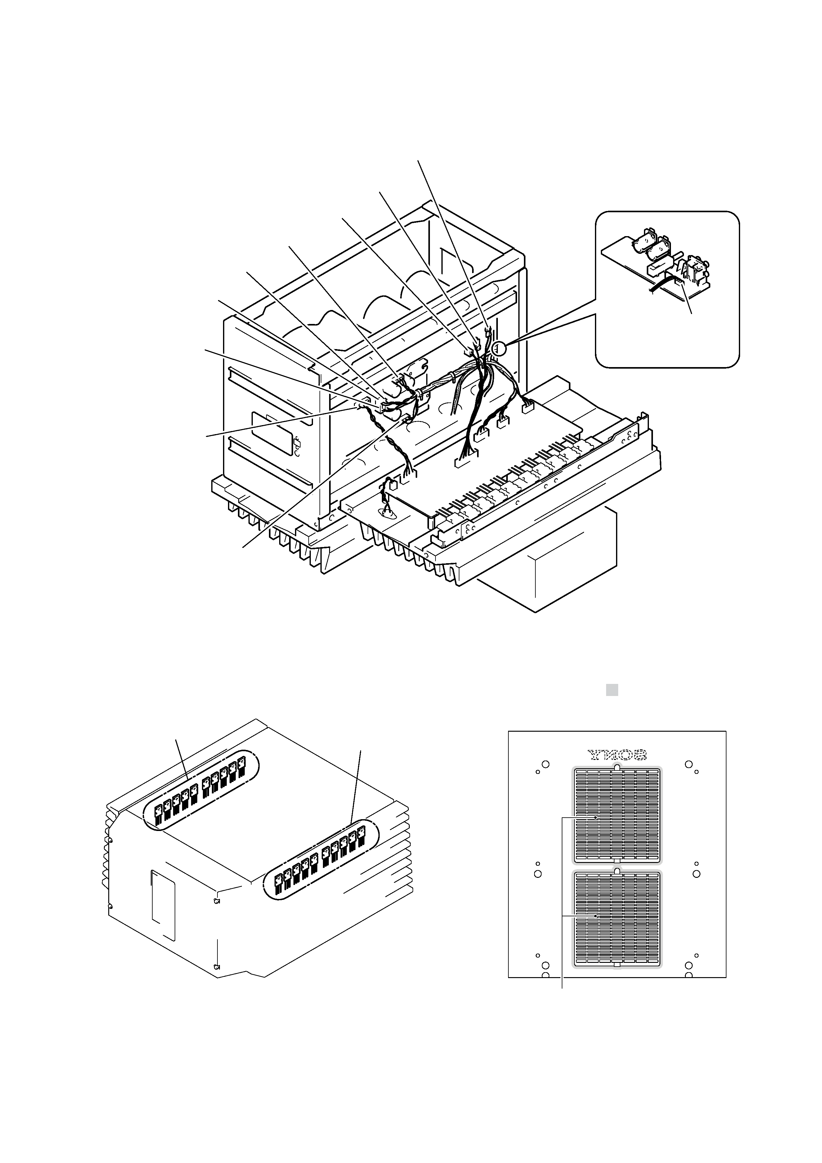
· SECURING THE GRILL (A)
When securing the grill (A) to the top panel, use the Sony bond
SC608LV (7-432-912-48). (
)
Top panel (Buttom side)
· SERVICE POSITION
When performing servicing, use a table about 15 cm as shown in
the figure.
· REPLACING THE POWER TRANSISTOR
When replacing the power transistors (Q304 to Q313: L-ch, Q404
to Q413: R-ch), replace all ten together.
L ch : Q304 to Q313
R ch : Q404 to Q413
Grille (A)
4
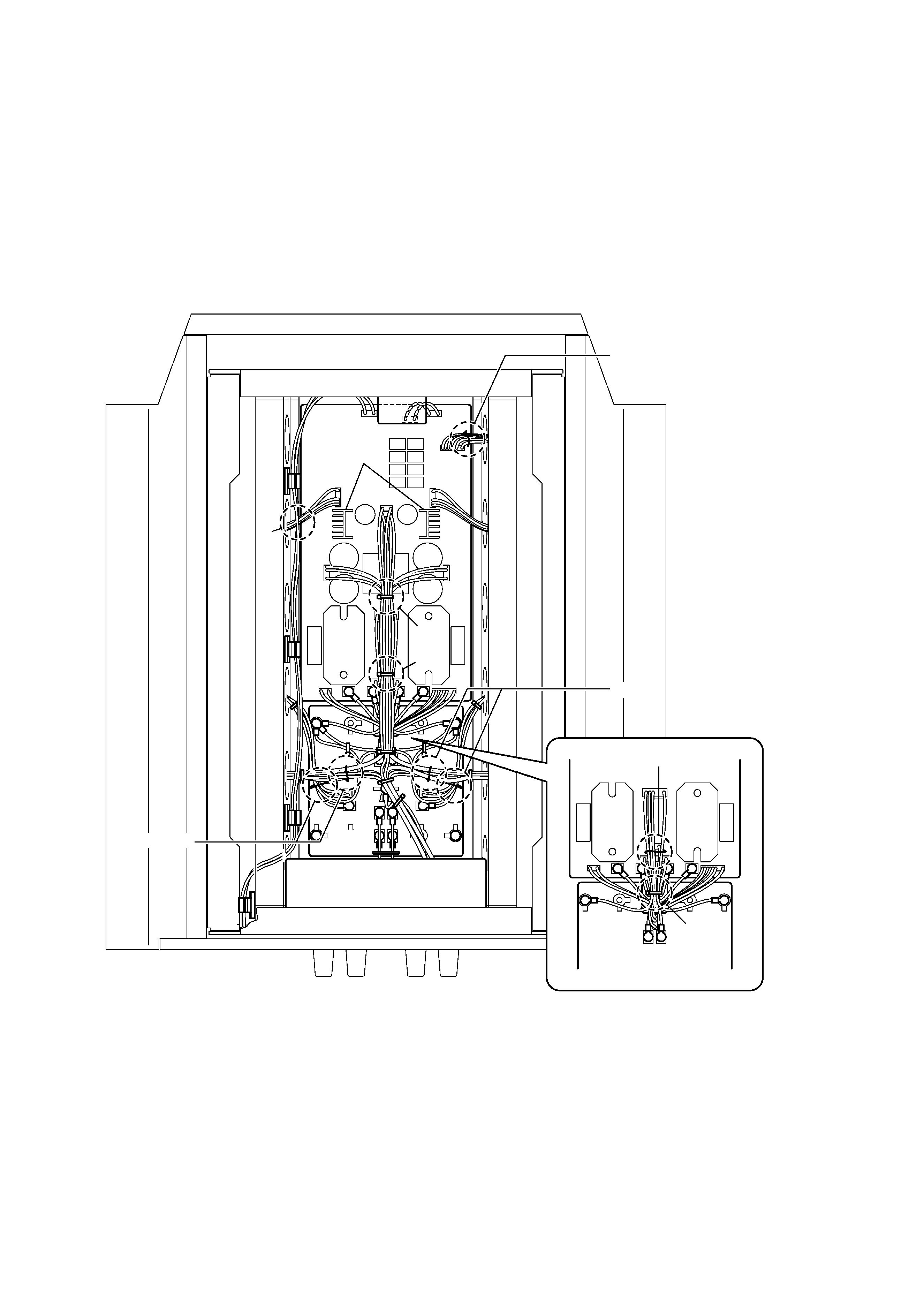
· NOTE ON ARRANGING WIRES
As how the wires in this unit are drawn affect the sound quality,
note down the positions of wires before beginning servicing.
After repairs, arrange the wires as follows.
A : After binding wires, push down.
B : Bind avoiding touching the heatsink.
C : Bind avoiding touching the wires below (binder A).
D : Arrange so that the wires from CN802 pass below the wires
from CN2.
INPUT board
AC/PS board
CN802
CN2
PS B
board
A
B
C
D
Heatsink
Lead pin
Lead pin
Lead pin
Lead pin
5
SECTION 2
GENERAL
This section is extracted from
instruction manual.