MICROFILM
SERVICE MANUAL
INTEGRATED STEREO AMPLIFIER
AEP Model
UK Model
E Model
Australian Model
Chinese Model
SPECIFICATIONS
TA-FA30ES
Photo: GOLD model
System
Power Amplifier: Pure-complementary SEPP MOS FET power
amplifier with all stages directly coupled
Preamplifier: Low-noise, high-gain equalizer amplifier
Power section: Large-capacity power supply advanced STD
Rated output
4 ohms, 120 W + 120 W (DIN 0.7%, 1 kHz)
8 ohms, 80 W + 80 W (DIN 0.7%, 1 kHz)
Speaker Impedance
4 to 16 ohms
Output bandwidth (8 ohms)
10 Hz to 100 kHz (at 40 W output, and high-frequency distortion
rate of 0.08%)
Total harmonic distortion
0.008% (at 8 ohms, 10 W output)
Damping factor
100 (8 ohms, 1 kHz)
Intermodulation (1M) distortion (60 Hz : 7 kHz = 4 : 1)
0.008% (8 ohms)
Throughrate
125 V/µ sec, 250 V/µ sec (Inside)
Residual noise
Less than 100 µV (network A)
Equalizer deviation
PHONO MM: 20 Hz to 20 kHz, ± 5 dB
Frequency response
TUNER, CD, AUX, TAPE1/DAT, TAPE2/MD: 7 Hz to
100 kHz
dB
S/N
PHONO MC: 78 dB (network A, 0.5 mV)
MM: 95 dB (network A, 5 mV)
TUNER, CD, AUX, TAPE1/DAT, TAPE2/MD: 105 dB
Inputs
Input sensitivity and impedance
PHONO MC: 0.17 mV, 100 ohms
MM: 2.5 mV, 50 kilohms
TUNER, CD, AUX, TAPE1/DAT, TAPE2/MD: 150 mV,
20 kilohms
Maximum input capability (1 kHz)
PHONO MC: 9 mV
MM: 150 mV
Outputs
Output level/impedance
REC OUT 1, 2: 150 mV, 1 kilohm
PHONES: 10 mW (at 8 ohms)
Tone controls
BASS (100 Hz): ± 7 dB
TREBLE (10 kHz): ± 7 dB
General
Power requirements
230 V AC, 50/60 Hz
Power consumption
220 W
Dimensions (approx) (w/h/d)
430
× 150 × 415 mm incl. projecting parts and controls
Mass (approx)
11.0 kg
Supplied accessories
Remote commander (remote ) RM-S326 (1)
Sony batteries R6 (size-AA) (2)
Design and specifications are subject to change without notice.
+0
3

2
TABLE OF CONTENTS
1.
GENERAL
Location of Controls .......................................................
3
2.
DISASSEMBLY ......................................................... 4
3.
ELECTRICAL ADJUSTMENTS ......................... 6
4.
DIAGRAMS
4-1. Notes for Printed Wiring Boards
and Schematic Diagrams ................................................
8
4-2. Printed Wiring Boards INPUT Section ...................
9
4-3. Schematic Diagram INPUT Section ......................... 11
4-4. Printed Wiring Boards MAIN Section .................... 13
4-5. Schematic Diagram MAIN Section .......................... 15
4-6. Printed Wiring Boards PANEL Section .................. 17
4-7. Schematic Diagram PANEL Section ....................... 19
4-8. Printed Wiring Boards POWER Section ................. 21
4-9. Schematic Diagram POWER Section ..................... 23
4-10. IC Pin Function Description ........................................... 26
5.
EXPLODED VIEWS ................................................ 27
6.
ELECTRICAL PARTS LIST ............................... 31
SAFETY-RELATED COMPONENT WARNING!!
COMPONENTS IDENTIFIED BY MARK
! OR DOTTED
LINE WITH MARK
! ON THE SCHEMATIC DIAGRAMS
AND IN THE PARTS LIST ARE CRITICAL TO SAFE
OPERATION. REPLACE THESE COMPONENTS WITH
SONY PARTS WHOSE PART NUMBERS APPEAR AS
SHOWN IN THIS MANUAL OR IN SUPPLEMENTS PUB-
LISHED BY SONY.
3
SECTION 1
GENERAL
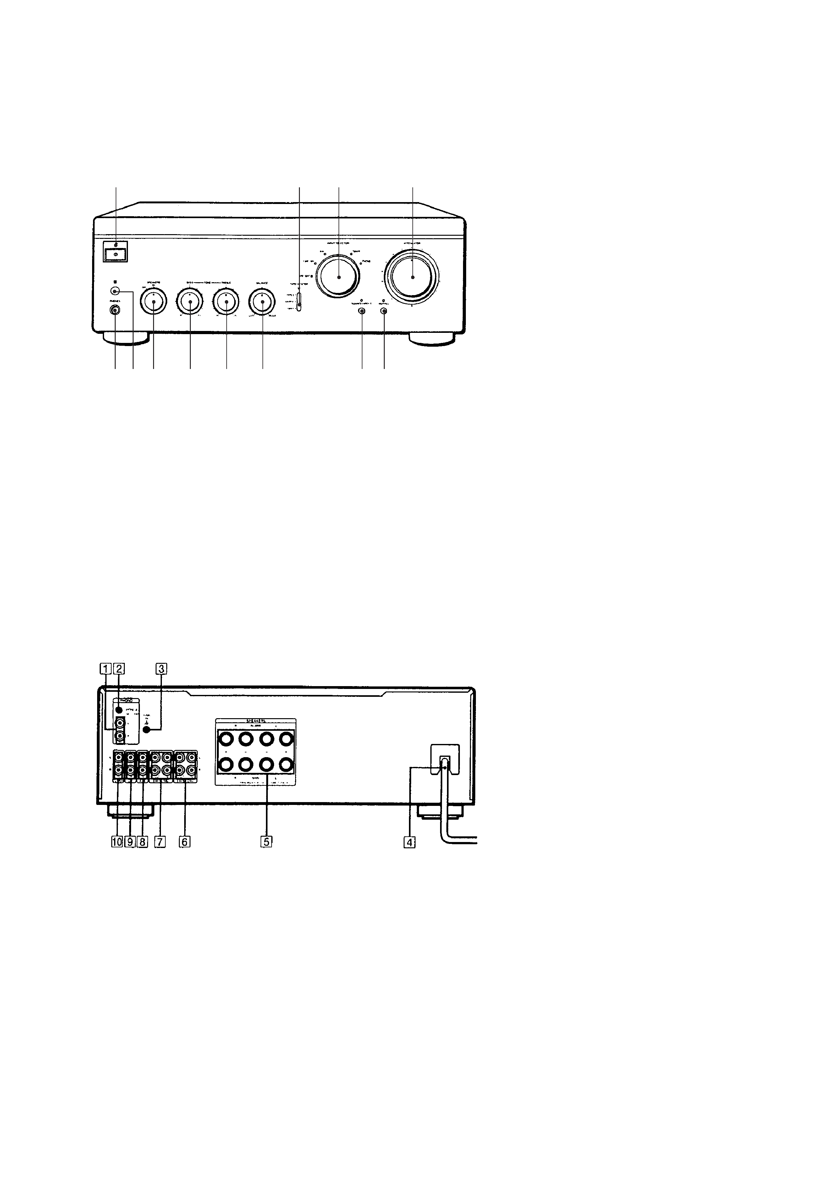
LOCATION OF CONTROLS
Front Panel
Rear Panel
1 U (Power) switch and indicator
2 TAPE MONITOR switch and indicator
3 INPUT SELECTOR switch and indicator
4 ATTENUATOR control
5 PHONES jack
6 Remote control sensor
7 SPEAKERS switch
8 BASS control
9 TREBLE control
!º BALANCE control
!¡ SOURCE DIRECT switch and indicator
!TM MUTING swith and indicator
1
2
3
4
56 7
8
9
!º
!¡ !TM
1 PHONO
2 CARTRIDGE MM/MC
3 SIGNAL GND y
4 Mains lead
5 SPEAKERS MAIN/BI-WIRE
6 TAPE 1/DAT
7 TAPE 2/MD
8 AUX
9 CD
!º TUNER
4
6 connector
(CN2)
4 connector
(CN700)
1 connector
(CN103)
3 connector
(CN303)
2 connector
(CN102)
7 two screws
(3
× 8)
7 three screws
(3
× 8)
7 two screws
(3
× 8)
7 four screws
(3
× 8)
7 two screws
(3
× 8)
5 connector
(CN503)
8 sub panel section
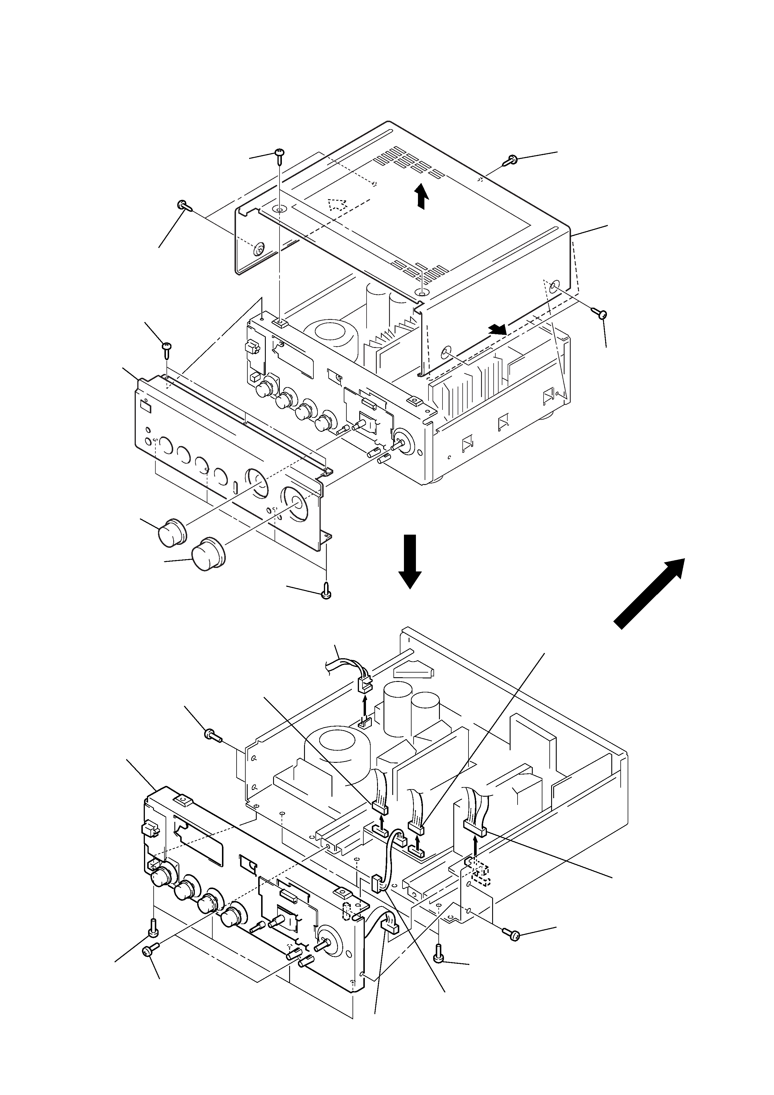
CASE, FRONT PANEL
SUB PANEL SECTION
Note: Follow the disassembly procedure in the numerical order given.
SECTION 2
DISASSEMBLY
1 two screws
(CASE 3 TP2)
1 screw
(CASE 3 TP2)
1 two screws
(CASE 3 TP2)
2 case
(413235)
1 two screws
(CASE 3 TP2)
5 three screws
(3
× 8)
5 four screws
(3
× 8)
6 front panel
3 knob (SEL)
4 knob (VOL)
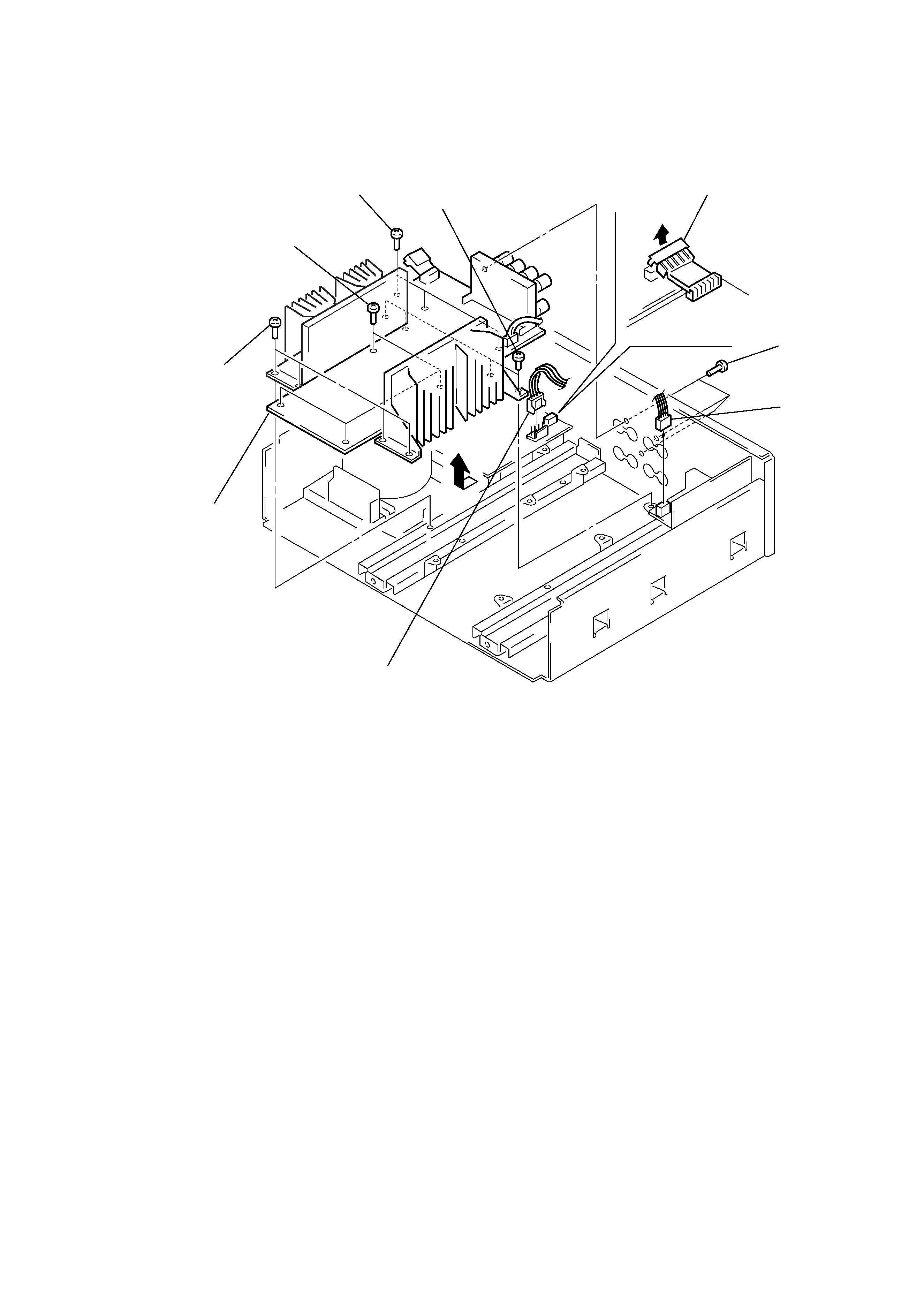
5
MAIN BOARD
2 connector
(CN752)
3 connector
(CN104)
1 connector
(CN751)
4 three screws
(BV/RING)
5 four screws
(3
× 8)
7 main board
6 four screws
(3
× 8)
5 four screws
(3
× 8)
5 three screws
(3
× 8)