-- 1 --
TA-AV661
US Model
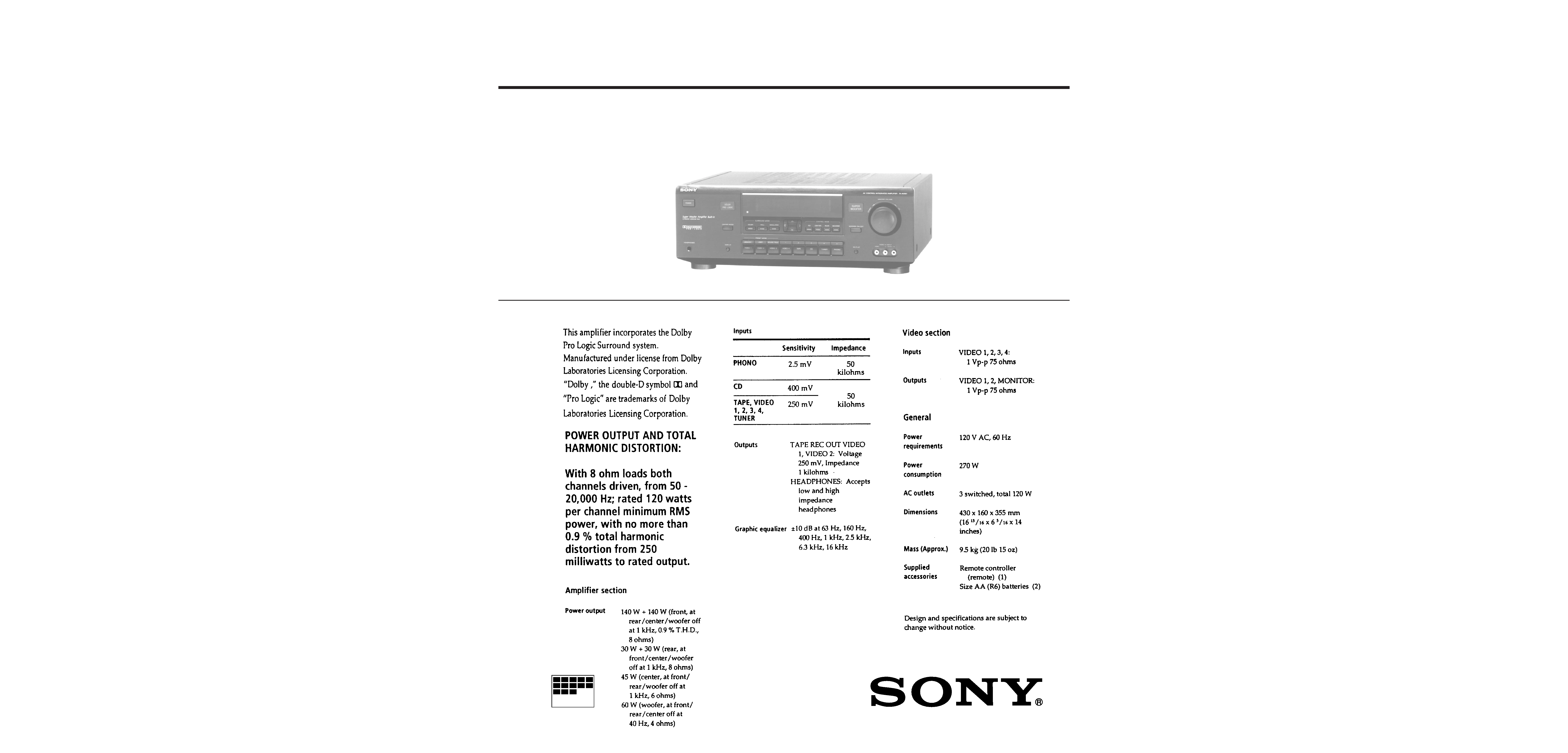
SPECIFICATIONS
AV CONTROL INTEGRATED AMPLIFIER
MICROFILM
SERVICE MANUAL

-- 2 --
TABLE OF CONTENTS
Section
Title
Page
SECTION 1.GENERAL ...................................................... 3
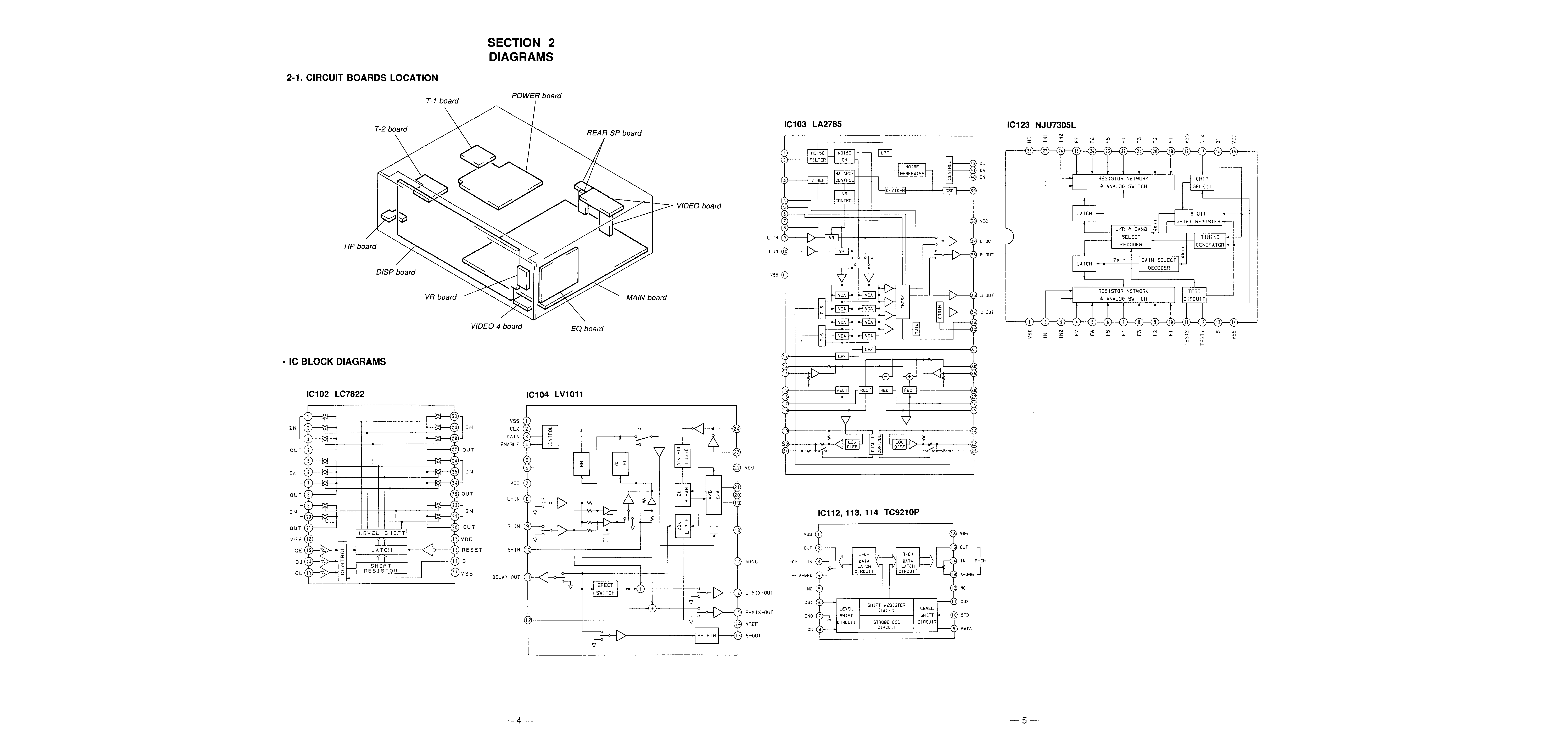
SECTION 2. DIAGRAMS
2-1.
Circuit Boards Location ..................................................... 4
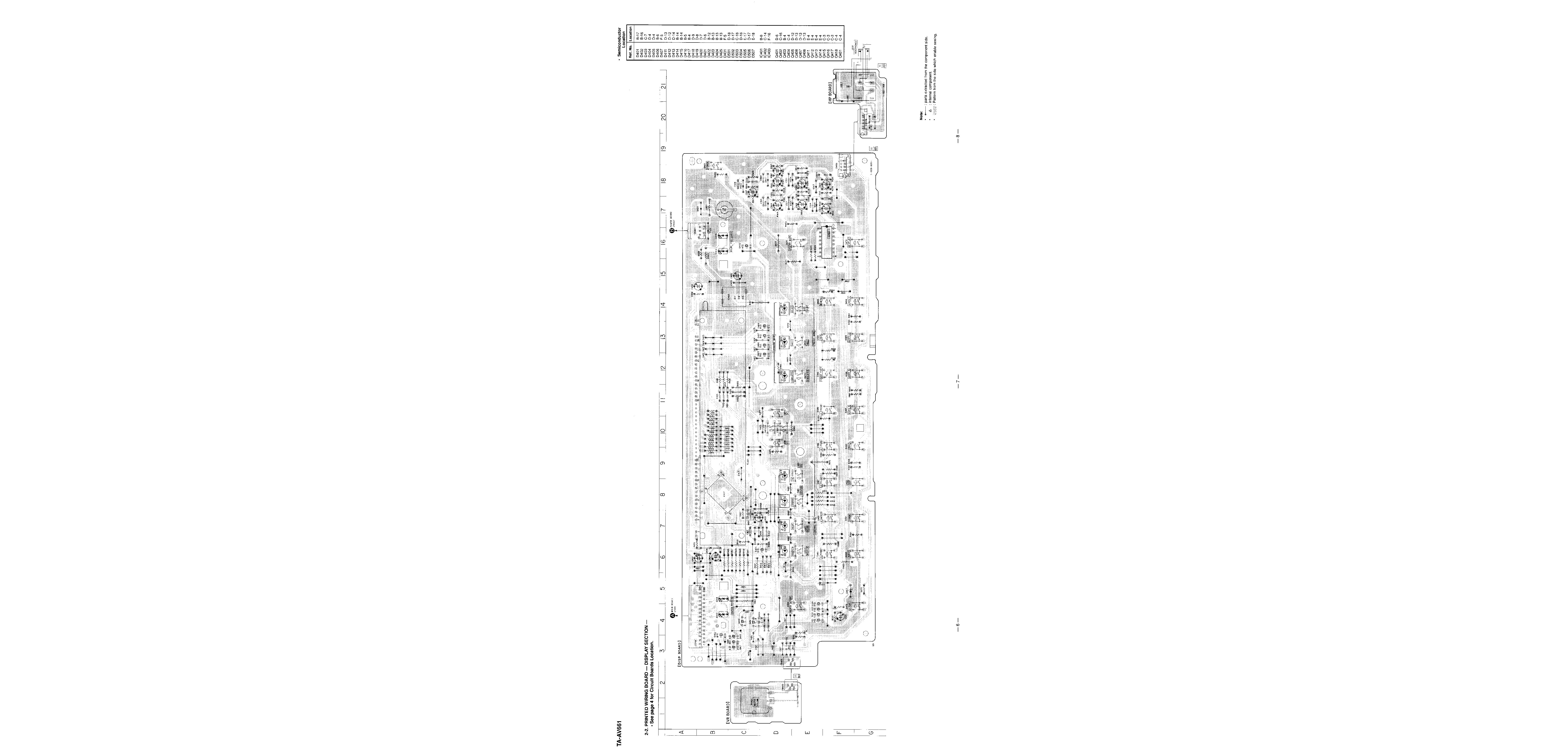
2-2.
Printed Wiring Board -- Display Section -- ..................... 6
2-3.
Schematic Diagram -- Display Section -- ........................ 9
2-4.
IC Pin Function
· IC401 System Control (µPD78043AGF-033-3B9) ........ 12
2-5.
Schematic Diagram -- Main Section -- .......................... 13
2-6.
Printed Wiring Board -- Main Section -- ....................... 17
SECTION 3. EXPLODED VIEWS
3-1.
Front Panel Section .......................................................... 21
3-2.
Back Panel Section ........................................................... 22
3-3.
Chassis Section ................................................................. 23
SECTION 4. ELECTRICAL PARTS LIST .................. 24
SAFETY CHECK-OUT
After correcting the original service problem, perform the
following safety checks before releasing the set to the customer:
Check the antenna terminals, metal trim, "metallized" knobs,
screws, and all other exposed metal parts for AC leakage. Check
leakage as described below.
LEAKAGE
The AC leakage from any exposed metal part to earth ground and
from all exposed metal parts to any exposed metal part having a
return to chassis, must not exceed 0.5 mA (500 microampers).
Leakage current can be measured by any one of three methods.
1. A commercial leakage tester, such as the Simpson 229 or
RCA WT-540A. Follow the manufacturers' instructions to
use these instruments.
2. A battery-operated AC milliammeter. The Data Precision 245
digital multimeter is suitable for this job.
3. Measuring the voltage drop across a resistor by means of a
VOM or battery-operated AC voltmeter. The "limit"
indication is 0.75 V, so analog meters must have an accurate
low-voltage scale. The Simpson 250 and Sanwa SH-63Trd
are examples of a passive VOM that is suitable. Nearly all
battery operated digital multimeters that have a 2V AC range
are suitable. (See Fig. A)
Fig. A. Using an AC voltmeter to check AC leakage.
To Exposed Metal
Parts on Set
0.15µF
1.5k
AC
voltmeter
(0.75V)
Earth Ground
SAFETY-RELATED COMPONENT WARNING !!
COMPONENTS IDENTIFIED BY MARK
! OR DOTTED
LINE WITH MARK
! ON THE SCHEMATIC DIAGRAMS
AND IN THE PARTS LIST ARE CRITICAL TO SAFE
OPERATION. REPLACE THESE COMPONENTS WITH
SONY PARTS WHOSE PART NUMBERS APPEAR AS
SHOWN IN THIS MANUAL OR IN SUPPLEMENTS
PUBLISHED BY SONY.
[Lighting of all FLs and LEDs]
While pressing 3 button, connect the power supply plug to the
outlet, the FL tubes and LEDs light up.
[Key Check]
With all the FLs and LEDs lit, when the 3 button and
WOOFER ON/OFF button are pressed simultaneously, "SET **"
is displayed.
When the 3 button and WOOFER ON/OFF button are pressed
simultaneously again, the Key Check mode is set and "KEY 0" is
displayed.
Each time a button other than POWER is pressed, the display
will count up to "KEY 30".
A button already pressed will not be counted when pressed again.
When the button is pressed for the 31st time, "AMP" is displayed
and the key check mode is ended.
Note: The ** of "SET **" differs according to the version of the
microprocessor.
To exit the test mode, press the POWER button.
· Abbreviation
FL : Fluorescent Indicator Tube
-- 3 --
SECTION 2
GENERAL
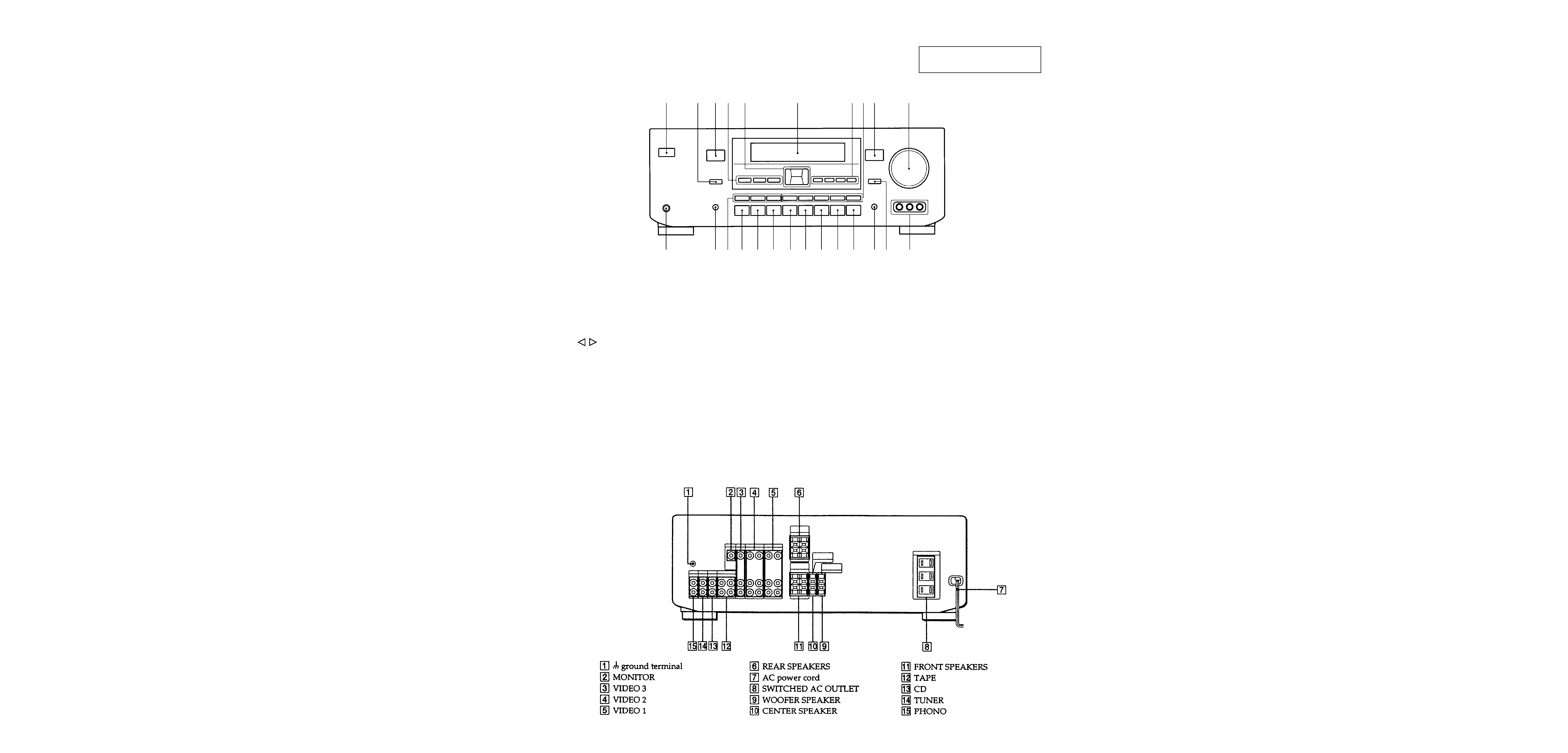
FRONT PANEL
This section is extracted from
instruction manual.
REAR PANEL
12 34 5
6
789
!º
!¡
!TM!£!¢ ! !§ !¶ !· !ª @º @¡ @TM@£ @¢
!£ PRESET MODE buttons
(MEMORY, USER, SOUND FIELD)
!¢ VIDEO 1 button
! VIDEO 2 button
!§ VIDEO 3 button
!¶ VIDEO 4 button
!· TAPE button
!ª CD button
@º TUNER button
@¡ PHONO button
@TM EQ FLAT button
@£ WOOFER ON/OFF button
@¢ VIDEO 4 INPUT jack
(VIDEO, AUDIO L/R)
1 POWER button
2 CENTER MODE button
3 DOLBY PRO LOGIC indicator
4 SURROUND MODE buttons
(DOLBY, HALL, SIMULATED)
5 / /¢/>/ button
6 Display Window
7 CONTROL MODE buttons
(EQ, CENTER, REAR, WOOFER)
8 Numeric buttons (1-5)
9 SUPER WOOFER indicator
!º MASTER VOLUME knob
!¡ HEADPHONES jack
!TM DISPLAY button