-- 1 --
SERVICE MANUAL
US Model
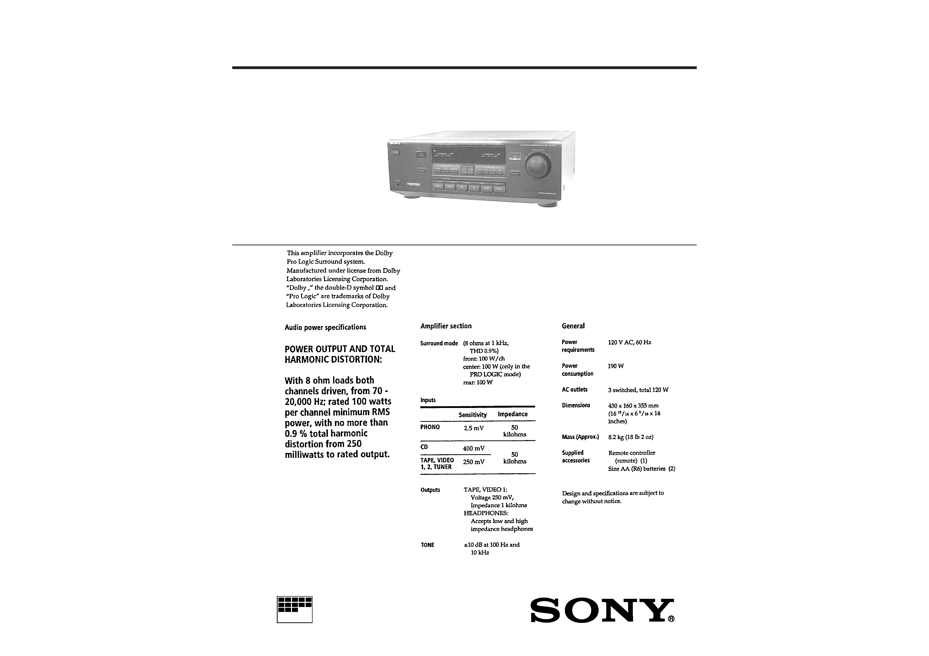
INTEGRATED AV AMPLIFIER
MICROFILM
TA-AV571
SPECIFICATIONS
-- 2 --
TABLE OF CONTENTS
1. SERVICING NOTE .......................................................... 3
2. GENERAL .......................................................................... 4
3. DIAGRAMS
3-1. Circuit Boards Location ........................................................ 5
3-2. Waveforms ........................................................................... 6
3-3. Schematic Diagram -- Main Section -- .............................. 7
3-4. Printed Wiring Board -- Main Section -- .......................... 11
3-5. Printed Wiring Board -- Power Section -- ........................ 13
3-6. Printed Wiring Board -- Display Section -- ...................... 15
3-7. Schematic Diagram -- Display Section -- ........................ 17
3-8. IC Block Diagrams ............................................................. 19
3-9. IC Pin Function
· IC401
µPD78042FGF-036-3BP (RF System Control) .... 21
4. EXPLODED VIEWS
4-1. Case and Back Panel Section .............................................. 23
4-2. Front Panel Section ............................................................. 24
4-3. Chassis Section ................................................................... 25
5. ELECTRICAL PARTS LIST ........................................ 26
SAFETY-RELATED COMPONENT WARNING !!
COMPONENTS IDENTIFIED BY MARK
! OR DOTTED LINE
WITH MARK
! ON THE SCHEMATIC DIAGRAMS AND IN
THE PARTS LIST ARE CRITICAL TO SAFE OPERATION.
REPLACE THESE COMPONENTS WITH SONY PARTS
WHOSE PART NUMBERS APPEAR AS SHOWN IN THIS
MANUAL OR IN SUPPLEMENTS PUBLISHED BY SONY.
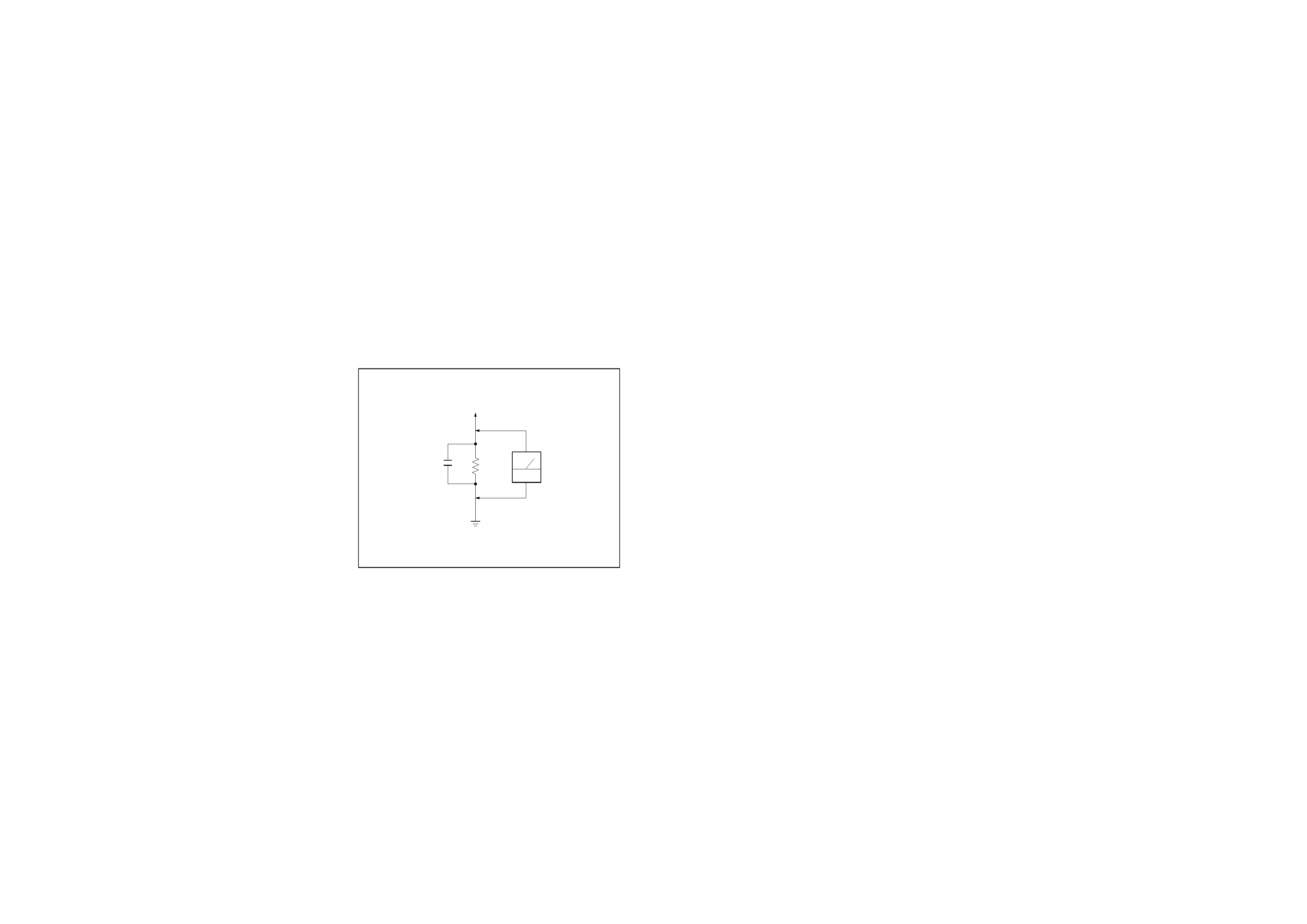
To Exposed Metal
Parts on Set
0.15µF
1.5k
AC
voltmeter
(0.75V)
Earth Ground
SAFETY CHECK-OUT
After correcting the original service problem, perform the follow-
ing safety checks before releasing the set to the customer:
Check the antenna terminals, metal trim, "metallized" knobs, screws,
and all other exposed metal parts for AC leakage. Check leakage as
described below.
LEAKAGE
The AC leakage from any exposed metal part to earth Ground and
from all exposed metal parts to any exposed metal part having a
return to chassis, must not exceed 0.5 mA (500 microampers). Leak-
age current can be measured by any one of three methods.
1. A commercial leakage tester, such as the Simpson 229 or RCA
WT-540A. Follow the manufacturers' instructions to use these
instruments.
2. A battery-operated AC milliammeter. The Data Precision 245
digital multimeter is suitable for this job.
3. Measuring the voltage drop across a resistor by means of a VOM
or battery-operated AC voltmeter. The "limit" indication is 0.75
V, so analog meters must have an accurate low-voltage scale.
The Simpson 250 and Sanwa SH-63Trd are examples of a pas-
sive VOM that is suitable. Nearly all battery operated digital
multimeters that have a 2V AC range are suitable. (See Fig. A)
Fig. A. Using an AC voltmeter to check AC leakage.
-- 3 --
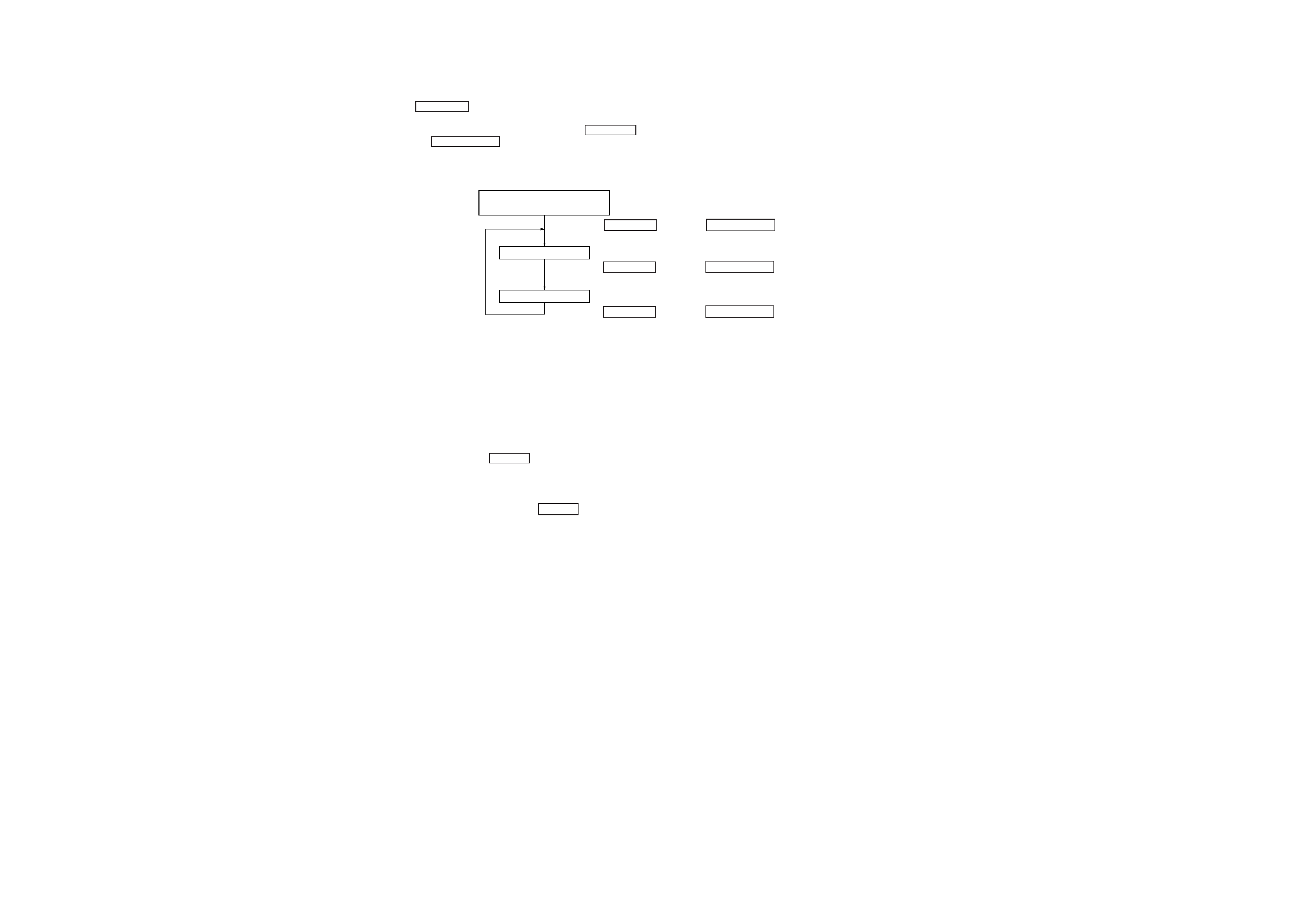
[Fluorescent Indicator Tube, LED All Lit, and Key Check Mode]
1. When the plug is inserted into the outlet while pressing the
3 CLASSIC button, the fluorescent indicator tube and LED
will light up completely.
2. The mode changes as follows each time the 3 CLASSIS button
and DBFB ON/OFF button are pressed together after 1.
Sequence of Service Modes
SECTION 1
SERVICING NOTE
Fluorescent Indicator
Tube and LED Check Mode*1
AMP check mode*2
KEY check mode*3
· Press the 3 CLASSIC button and DBFB ON/OFF
button at the same time.
· Press the 3 CLASSIC button and DBFB ON/OFF
button at the same time.
· Press the 3 CLASSIC button and DBFB ON/OFF
button at the same time.
*1 For checking if the fluorescent indicator tube and LED are lit
completely
*2 When the AMP check mode is set, "AMP" is displayed on the
fluorescent indicator tube. As this mode is not used for servic-
ing, perform step 2 to enter the KEY check mode.
*3 When the KEY check mode is set, "KEY 0" is displayed on the
fluorescent indicator tube. Each press of the button is counted.
(This excludes the POWER button)
When all buttons are pressed, the AMP check mode is set.
Buttons pressed once will not be counted when pressed again.
3. To exit the test mode, press the POWER button.
-- 4 --
SECTION 2
GENERAL
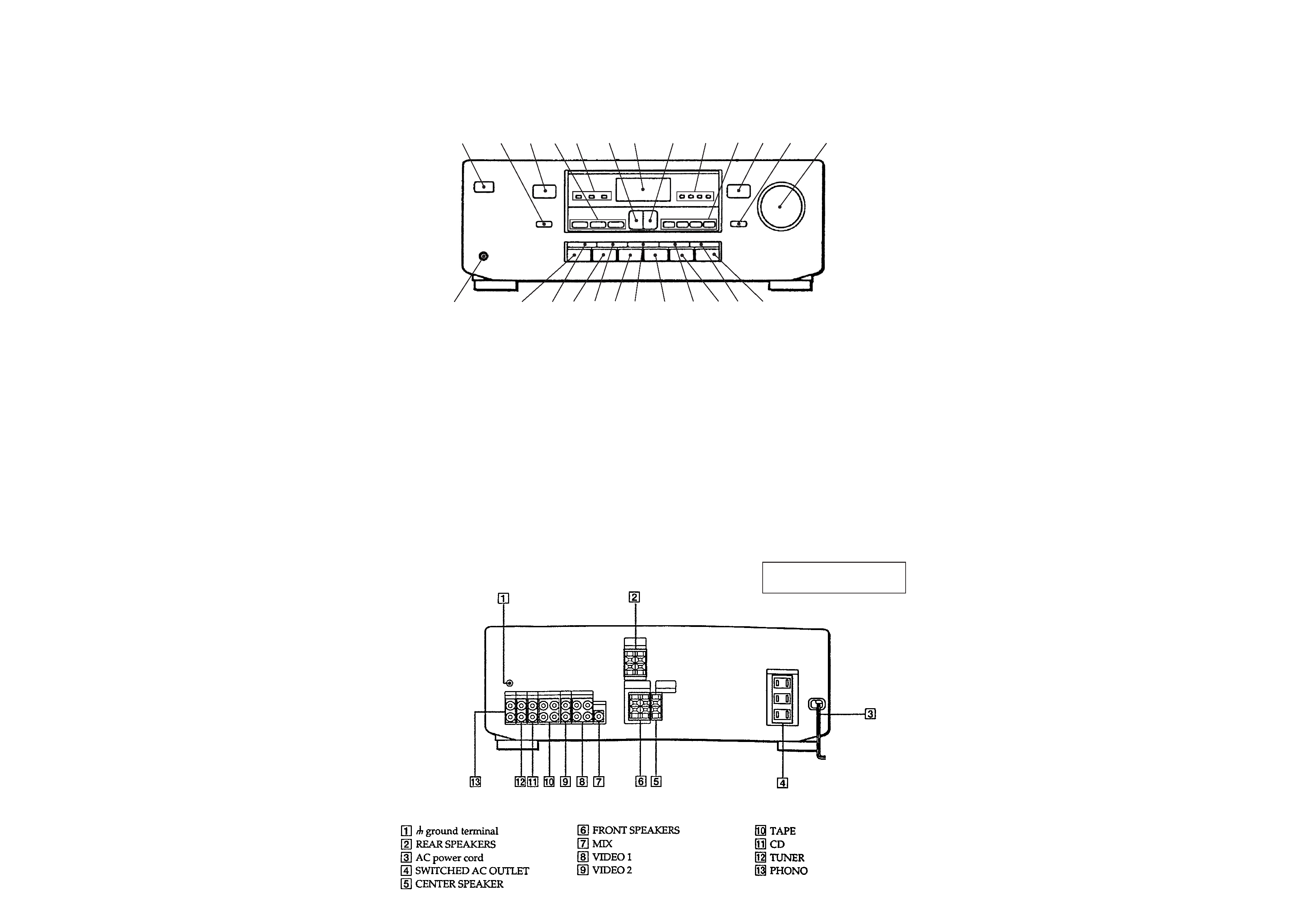
LOCATION OF PARTS AND CONTROLS
Front Panel
1 POWER button
2 CENTER MODE button
3 DOLBY PRO LOGIC indicator
4 SURROUND MODE buttons
(DOLBY, HALL, SIMULATED)
5 SURROUND indicators
(DOLBY, HALL, SIMULATED)
6 button
7 Display window
8 + button
9 SOUND CONTROL indicators
(BASS, TREBLE, CENTER, REAR)
!º CONTROL MODE buttons
(BASS, TREBLE, CENTER, REAR)
!¡ DBFB indicator
!TM DBFB ON/OFF button
!£ MASTER VOLUME Knob
!¢ PHONO button
! 5 GAME button
!§ TUNER button
!¶ 4 MOVIE button
!· CD button
!ª 3 CLASSIC button
@º TAPE button
@¡ 2 POPS button
@TM VIDEO 2 button
@£ 1 ROCK button
@¢ VIDEO 1 button
@ PHONES jack
1
23 4 5
6
7
8
0
9
!¡
!TM
!£
!¢
!
!§
!¶
!·
!ª
@º
@¡
@TM
@£
@¢
@
This section is extracted from
instruction manual.
Rear Panel
-- 5 --
-- 5 --
SECTION 3
DIAGRAMS
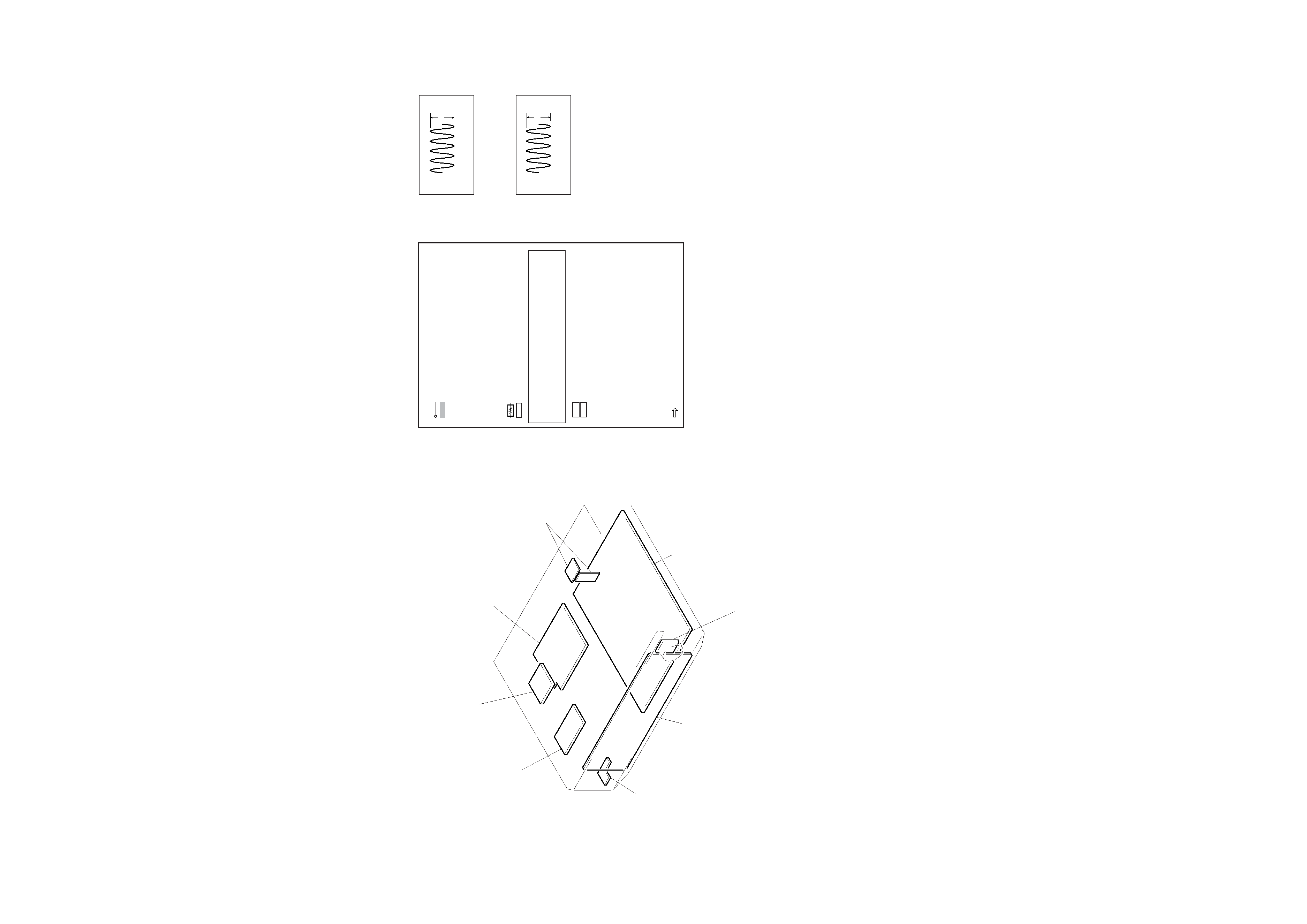
3-1. CIRCUIT BOARDS LOCATION
NOTE
·
: parts extracted from the component side.
·
: Pattern from the side which enable seeing.
NOTE
· All capacitors are in
µF unless otherwise noted. pF : µµF
50WV or less are not indicated except for electrolytics and
tantalums.
· All resistors are in
and 1/4W or less unless otherwise speci-
fied.
·
¢ : internal component.
·
: nonflammable resistor.
·
: panel designation.
THIS NOTE IS COMMON FOR PRINTED WIRING BOARDS
AND SCHEMATIC DIAGRAMS.
(In addition to this, the necessary note is printed in each
block.)
-- 6 --
MAIN SECTION
1
5.2Vp-p
3-2. WAVEFORMS
8MHz
T-2 board
T-1 board
POWER board
REAR SP board
MAIN board
VR board
DISPLAY board
H.P board
IC202 @¢
2
IC401 #¢ X1
4.2Vp-p
5MHz
PANEL SECTION
Note:
The components identi-fied by mark
! or dotted line with mark
! are critical for safety.
Replace only with part number specified.
·
B+
: B+ Line
·
B
: B Line
· Voltage and waveforms are dc with respect to ground under no-
signal conditions.
no mark : STOP
· Voltages are taken with a VOM (Input impedance 10M
).
Voltage variations may be noted due to normal production toler-
ances.
· Waveforms are taken with a oscilloscope.
Voltage variations may be noted due to normal production toler-
ances.
· Circled numbers refer to waveforms.
· Signal path.
:FM