FM Stereo
FM-AM Tuner
Operating Instructions
4-233-395-
14(1)
ST-SE570
ST-SE370
© 2001 Sony Corporation
Owner's Record
The model and serial numbers are located on the rear panel. Record the serial number
in the space provided below. Refer to them whenever you call upon your Sony dealer
regarding this product.
Model No.
Serial No.
2
WARNING
To prevent fire or shock hazard, do not
expose the unit to rain or moisture.
To avoid electrical shock, do not open
the cabinet. Refer servicing to qualified
personnel only.
To prevent fire, do not Cover the ventilation of the
apparatus with news papers, table-cloths, curtains,
etc. And don't place lighted candles on the apparatus.
To prevent fire or shock hazard, do not place objects
filled with liquids, such as vases, on the apparatus.
Don't throw a battery, dispose it as
the injurious wastes.
NOTICE FOR THE CUSTOMERS IN THE
U.S.A.
This symbol is intended to alert the user to
the presence of uninsulated "dangerous
voltage" within the product's enclosure that
may be of sufficient magnitude to constitute
a risk of electric shock to persons.
This symbol is intended to alert the user to
the presence of important operating and
maintenance (servicing) instructions in the
literature accompanying the appliance.
WARNING
This equipment has been tested and found to comply
with the limits for a Class B digital device, pursuant
to Part 15 of the FCC Rules. These limits are
designed to provide reasonable protection against
harmful interference in a residential installation. This
equipment generates, uses, and can radiate radio
frequency energy and, if not installed and used in
accordance with the instructions, may cause harmful
interference to radio communications. However, there
is no guarantee that interference will not occur in a
particular installation. If this equipment does cause
harmful interference to radio or television reception,
which can be determined by turning the equipment
off and on, the user is encouraged to try to correct the
interference by one or more of the following
measures:
Reorient or relocate the receiving antenna.
Increase the separation between the equipment and
receiver.
Connect the equipment into an outlet on a circuit
different from that to which the receiver is
connected.
Consult the dealer or an experienced radio/TV
technician for help.
CAUTION
You are cautioned that any changes or modifications
not expressly approved in this manual could void
your authority to operate this equipment.
Note to CATV system installer
This reminder is provided to call the CATV system
installer's attention to Article 820-40 of the NEC that
provides guidelines for proper grounding and, in
particular, specifies that the cable ground shall be
connected to the grounding system of the building, as
close to the point of cable entry as practical.
About This Manual
The instructions in this manual describe the
operation of the Sony ST-SE570 and
ST-SE370. Most operating procedures apply to
both. However, there are certain procedures
that may apply to only one of the tuners. These
are clearly indicated (e.g., ST-SE570 only).
Check the model number on the front of your
tuner so you'll know which instructions apply
to you.
In this manual, the display of ST-SE570 is used
for illustration purposes.
3
Table of Contents
Parts Identification
Main unit ............................................... 4
Getting Started
Unpacking ............................................. 5
Hooking up the system .......................... 5
Selecting the German display ................ 7
Storing FM stations automatically
(Auto-betical Select)* ..................... 7
Presetting radio stations ......................... 8
Basic Operations
Receiving preset stations ....................... 8
Advanced Tuner Operations
About the menu entry system ................ 9
Customizing the display ........................ 9
Receiving broadcasts ............................. 9
Tips for better FM reception ............... 10
Naming the preset stations .................. 11
Organizing the preset stations ............. 11
Using the Radio Data System (RDS)* ... 12
Additional Information
Precautions .......................................... 16
Troubleshooting ................................... 16
Specifications ...................................... 17
* European model only.
4
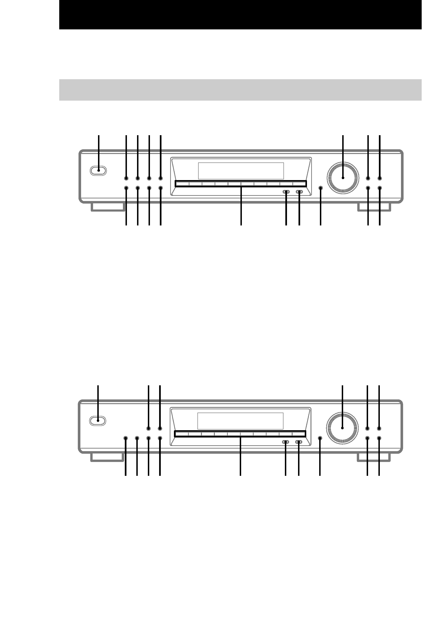
AUTO BETICAL SELECT qk (7, 12)
BAND qg (9, 10, 12)
CHARACTER 7 (11)
DIRECT qs (9)
DISPLAY 5 (10, 11, 13)
ENTER qa (9, 11, 12, 14)
EON NEWS/INFO 3 (13, 14)
EON TA 2 (13, 14)
FM MODE qh (9, 10)
Parts Identification
Main unit
The items are arranged in alphabetical order.
Refer to the pages indicated in parentheses ( ) for details.
MEMORY 4 (8, 11)
MENU 0 (9, 11, 14)
Numeric buttons qf (79)
POWER 1 (7, 8, 12)
PTY qj (14, 15)
RETURN 9 (9)
SHIFT qd (8, 11)
TUNE MODE 8 (8, 10)
TUNING/SELECT 6 (712, 14)
ST-SE570
ST-SE370
AUTO BETICAL SELECT (European model only)
qh (7, 12)
BAND qd (9, 10, 12)
CHARACTER 5 (11)
DIRECT 0 (9)
DISPLAY 3 (10, 11, 13)
ENTER 9 (9, 11, 12, 14)
FM MODE qf (9, 10)
MEMORY 2 (8, 11)
MENU 8 (9, 11, 14)
Numeric buttons qs (79)
POWER 1 (7, 8, 12)
PTY (European model only) qg (14, 15)
RETURN 7 (9)
SHIFT qa (8, 11)
TUNE MODE 6 (8, 10)
TUNING/SELECT 4 (712, 14)
1234567890
1
2 3
5 6
4
7
8
9
0
qa
qs
qd
qf
qg
qh
1234567890
1
2 3 4 5
7 8
6
9
0
qa
qs
qd
qf
qg
qh
qj
qk
5
Parts
Identification/Getting
Started
Unpacking
Check that you received the following items
with the tuner:
· Audio cord (1)
· AM loop antenna (1)
· FM wire antenna (1)
· EON connecting cord (ST-SE570 only, 1)
Hooking up the system
Before you get started
· Turn off the power to all components before
making any connections.
· Do not connect the mains lead until all of the
connections are completed.
· Be sure to make connections firmly to avoid
hum and noise.
· When connecting an audio cord, be sure to
match the colour-coded pins to the appropriate
jacks: White (left) to White; and Red (right) to
Red.
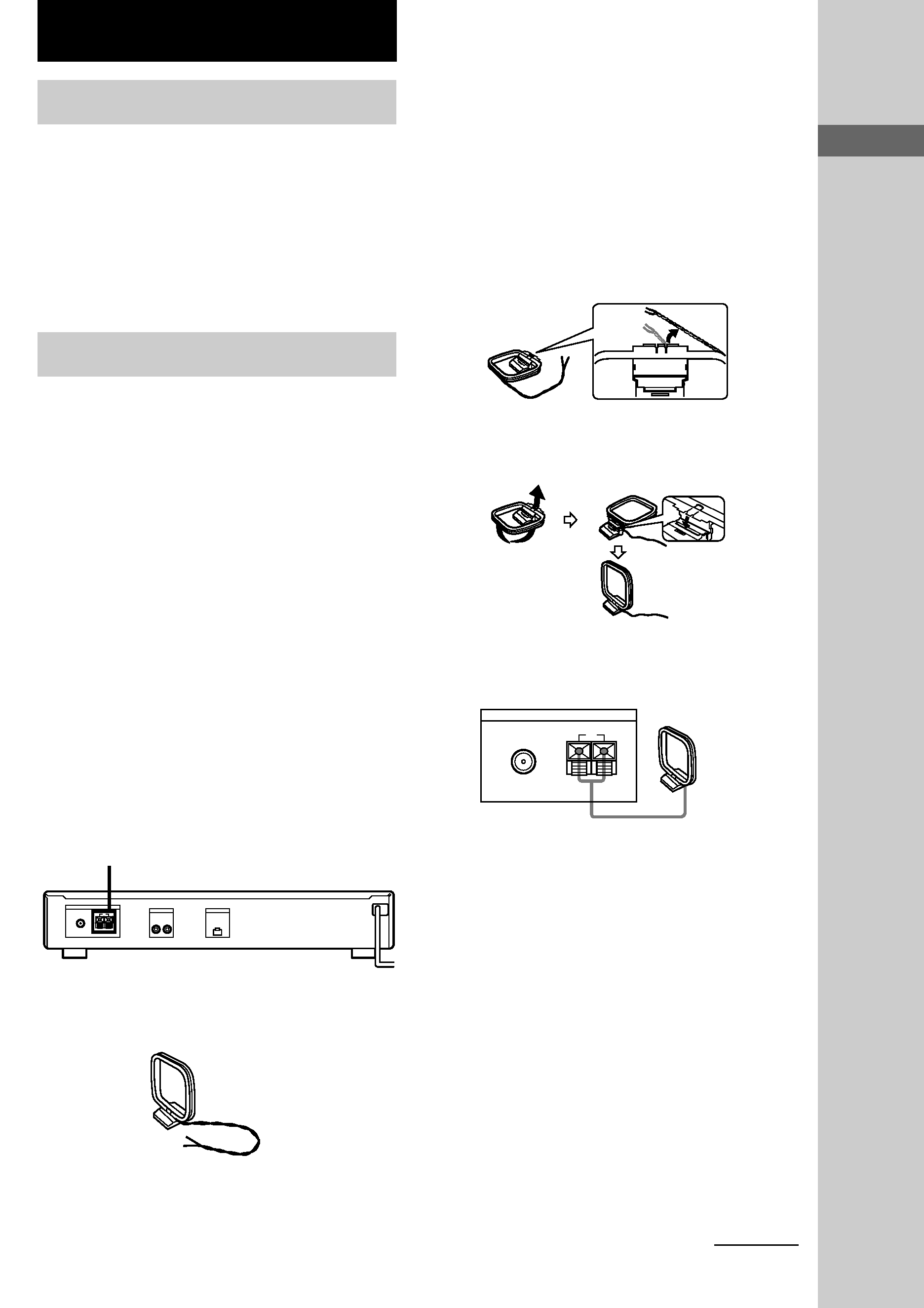
AM antenna hookups
This section describes how to connect the
supplied AM loop antenna. For the specific
location of the AM ANTENNA terminals, see
the illustration below.
What will I need?
· AM loop antenna (supplied) (1)
Getting Started
1 Before assembling the supplied
antenna, pull the lead wire out from the
slot in the antenna frame.
2 Unwrap 3 lengths of the braided lead
wire from around the frame of the
antenna.
Be careful to unwrap only the braided
section of the lead wire. Do not unwrap
more than 3 lengths of the lead wire. Also,
be careful not to unbraid the lead wire.
3 Assemble the supplied antenna as
shown below.
4 Connect the AM loop antenna to the AM
terminals on the back of this unit.
5 Adjust the antenna direction for the
best reception.
The AM loop antenna has a directivity
which detects the signal from some angles
more strongly than others. Set the antenna
to the orientation which provides the best
receiving condition.
If a high pitched noise (beat noise) occurs
when recording AM broadcasts, adjust the
position of the AM loop antenna so that the
noise disappears.
If you live in a building constructed of
reinforced concrete, or with a steel frame,
you may not be able to achieve good
reception since the radio waves become
weaker indoors. In this case, we recommend
connecting an optional antenna.
ANTENNA
FM
y
75
COAXIAL
AM
AM loop antenna
continued
AM ANTENNA
ANTENNA
OUTPUT
EON CONTROL
FM
y
75
COAXIAL
R
L
OUT
AM