1
MICROFILM
East European Model
CIS Model
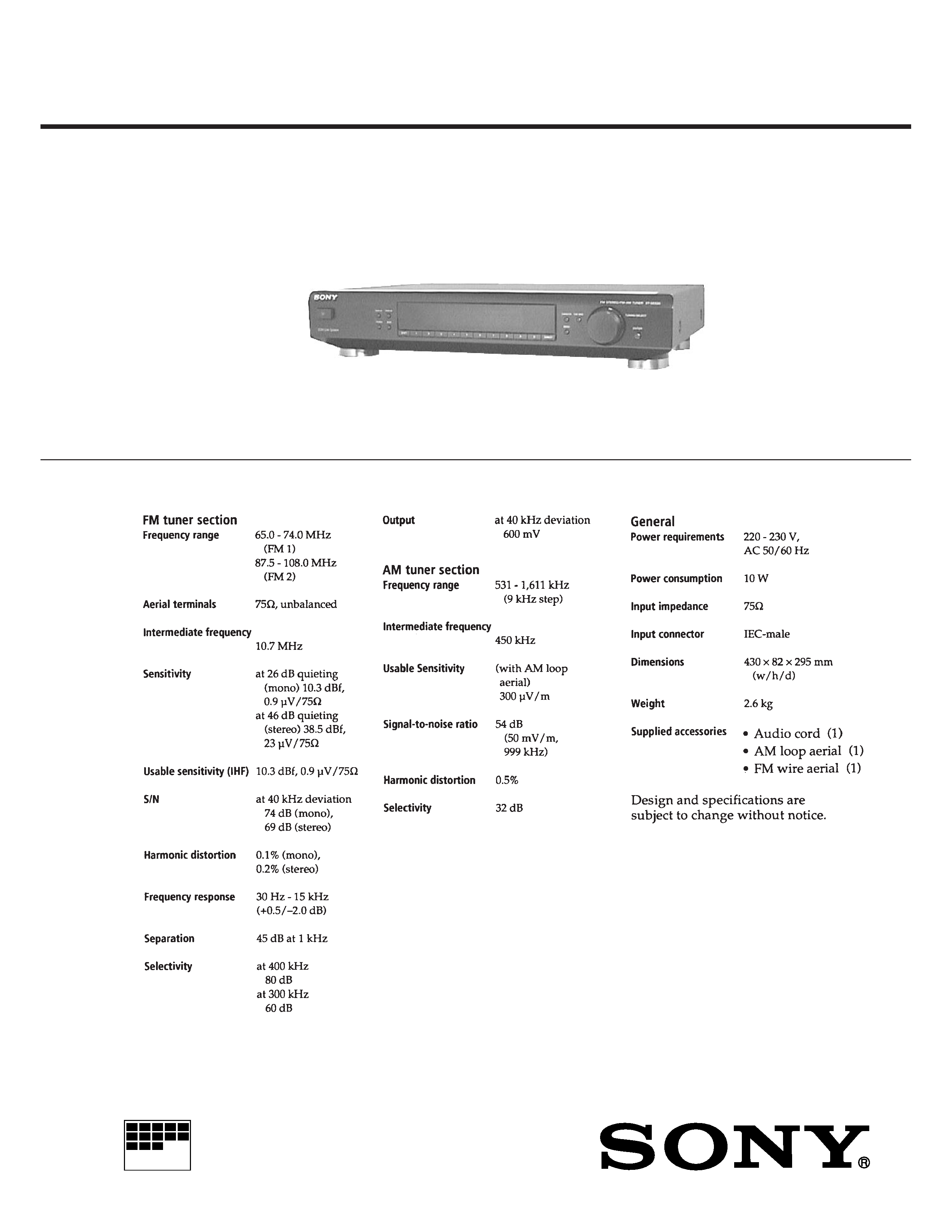
SPECIFICATIONS
SERVICE MANUAL
FM STEREO FM-AM TUNER
ST-SE520
2
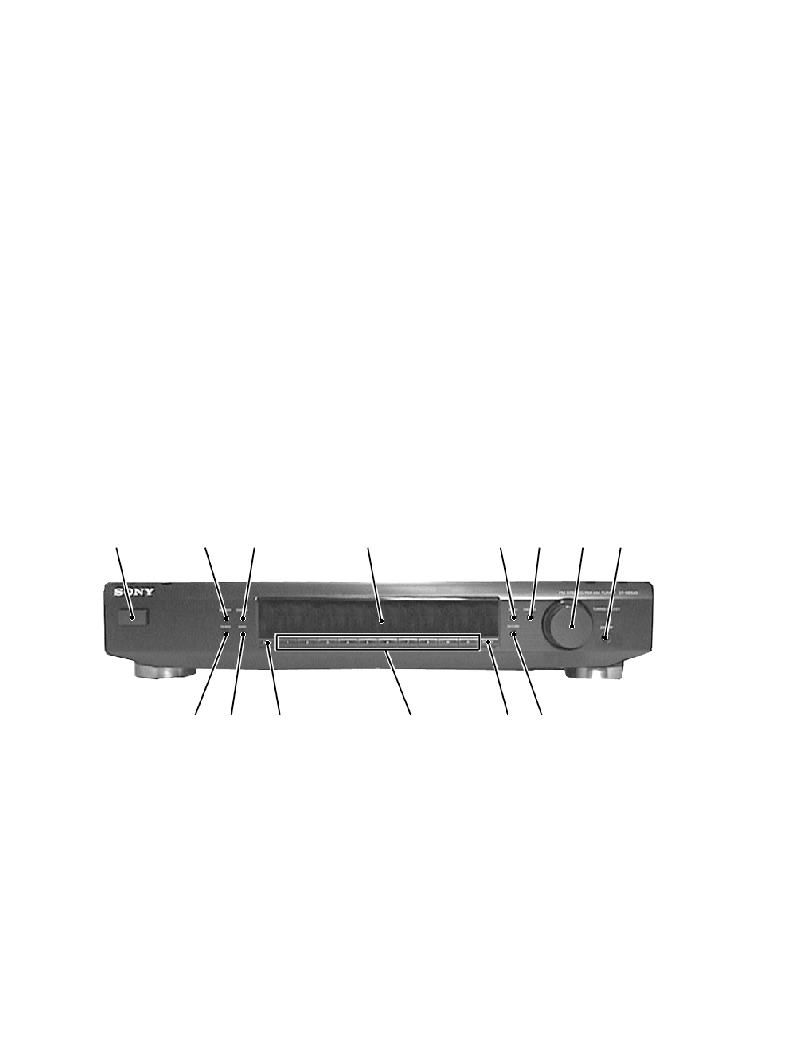
Front Panel Descriptions
SECTION 1
GENERAL
1 U (Power) switch
2 MEMORY button
3 DISPLAY button
4 Display window
5 MENU button
6 TUNER MODE button
7 TUNING/SELECT knob
8 ENTER button
9 FM MODE button
10 BAND button
11 SHIFT button
12 Numeric buttons
13 DIRECT button
14 RETURN button
SAFETY-RELATED COMPONENT WARNING !!
COMPONENTS IDENTIFIED BY MARK ! OR DOTTED LINE
WITH MARK ! ON THE SCHEMATIC DIAGRAMS AND IN
THE PARTS LIST ARE CRITICAL TO SAFE OPERATION.
REPLACE THESE COMPONENTS WITH SONY PARTS
WHOSE PART NUMBERS APPEAR AS SHOWN IN THIS
MANUAL OR IN SUPPLEMENTS PUBLISHED BY SONY.
TABLE OF CONTENTS
1. GENERAL .......................................................................... 2
2. TEST MODE ....................................................................... 3
3. ELECTRICAL ADJUSTMENTS ................................. 5
4. DIAGRAMS
4-1. Schematic Diagram Tuner Section .................................. 7
4-2. Printed Wiring Board Tuner Section ............................... 9
4-3. Schematic Diagram Display Section ............................ 11
4-4. Printed Wiring Board Display Section .......................... 13
4-5. IC Pin Function ................................................................... 15
4-6. IC Block Diagrams .............................................................. 17
5. EXPLODED VIEW ......................................................... 18
6. ELECTRICAL PARTS LIST ........................................ 19
78
2
3
46
5
1
10
11
13
12
914
3
NOTE : The preset data will be erased when this test mode is used. Therefore, take down the data before setting this mode and preset the data
again after completing operations in this mode.
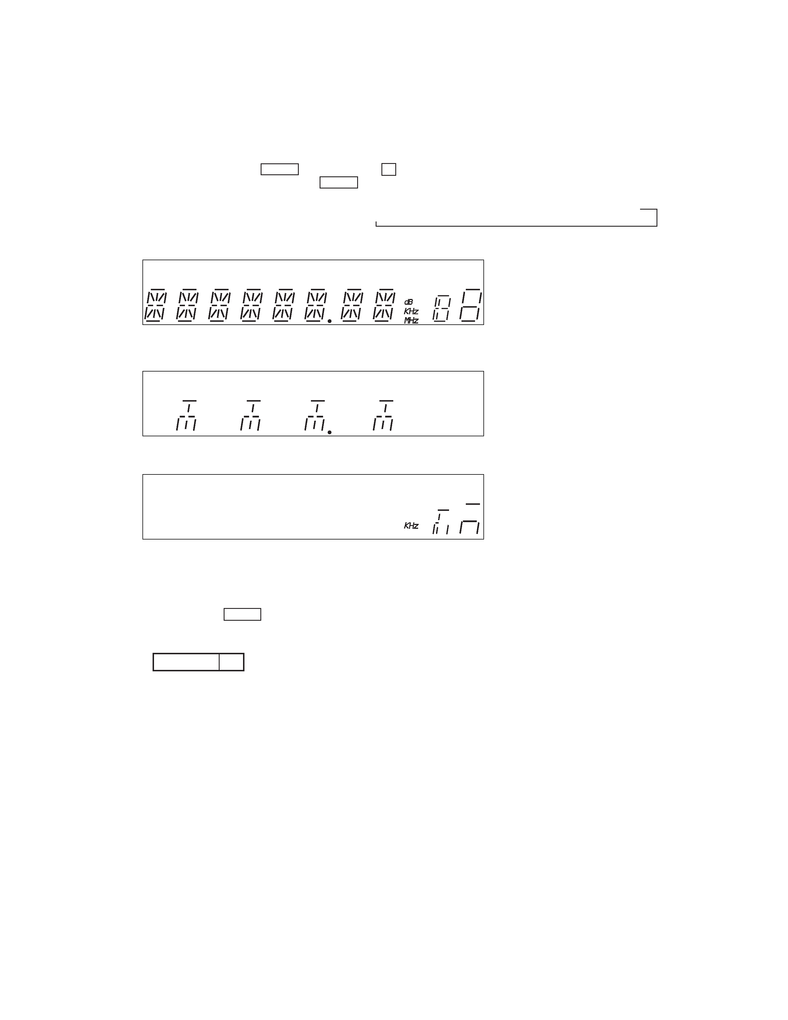
1. Display Tube and Key Check Mode
1-1. Display Tube Check
1-1-1. Turn OFF the power.
1-1-2. While pressing
1 and MENU together, turn ON U .
1-1-3. While continuously pressing
1 and MENU together, check the following.
Microcomputer version indication (1 sec) n All light up(1) n 8-digit test pattern(2) n 2-digit test pattern (3)
(1) All light up
(2) 8-digit test pattern
(3) 2-digit test pattern
The display changes every 500 msec.
1-2. Key Check
1-2-1. Release
1 and MENU . The KEY CHECK mode will be set.
1-2-2. All key numbers will be displayed.
1-2-3. Each time the key is pressed, the key number will be counted down.
Each key will be counted only once, at the first time.
1-2-4. When all keys have been pressed, the process will end and the factory preset will be entered.
SECTION 2
TEST MODE
n
Key Number
20
MONO
TA
AUTO
STEREO
MONO
TUNED
TA
NEWS
INFO
AUTO
PRESET
MEMORY
4
2. Entering the Factory Preset
To skip "1. Display Tube Key Check Mode", and factory preset:
(1) Turn OFF the power.
(2) While pressing
3 and MENU together, turn ON U .
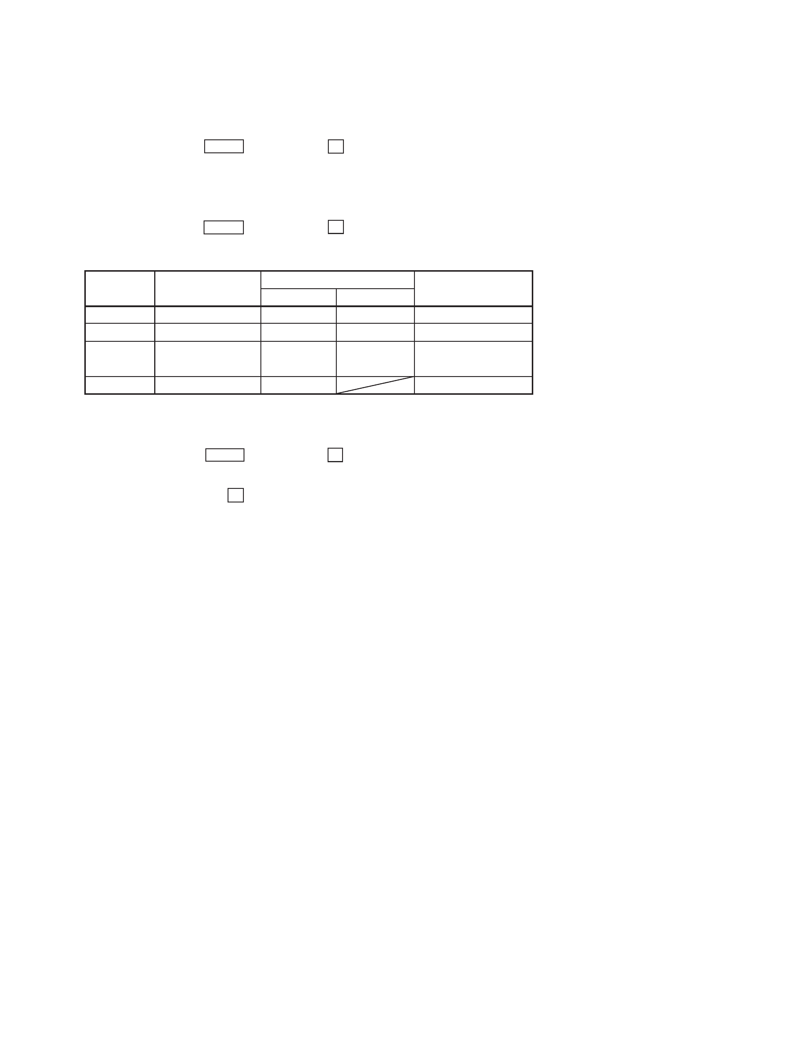
3. Circuit Check Mode
Set to the reception frequency that the circuit can receive (FM:STEREO stations). (Set the input level to above 70 dB.)
(1) Turn OFF the power.
(2) While pressing
4 and MENU together, turn ON U .
· The items in the following table will be checked automatically in order every 2 seconds.
AST signal =LOW
IF COUNT OK
SI LEVEL
70dB
ST signal=LOW
TUNED
IF
SIG L
ST
OK or NG
OK or NG
OK or NG
OK or NG
OK or NG
OK or NG
OK or NG
TB 101 NG
TB 101 NG
TB101 NG
4. Forced RESET
Clears all the RAMs and sets the initial state
(1) Turn OFF the power.
(2) While pressing
5 and MENU together, turn ON U .
NOTE : This model have PILOT/POLAR switching function. (Normally, do not use.)
(1) Turn OFF the power.
(2) While pressing
2, turn ON U .
Switches between PILOT and POLARITY and display the state.
Switches between PILOT and POLARITY each time this mode is performed.
Return the original state after completing the process.
Display
Items
FM STEREO
AM
Display
NG
>
=
IC 201 NG
RV201 adjustments
FM Signal Level Adjustment
SECTION 3
ELECTRICAL ADJUSTMENTS
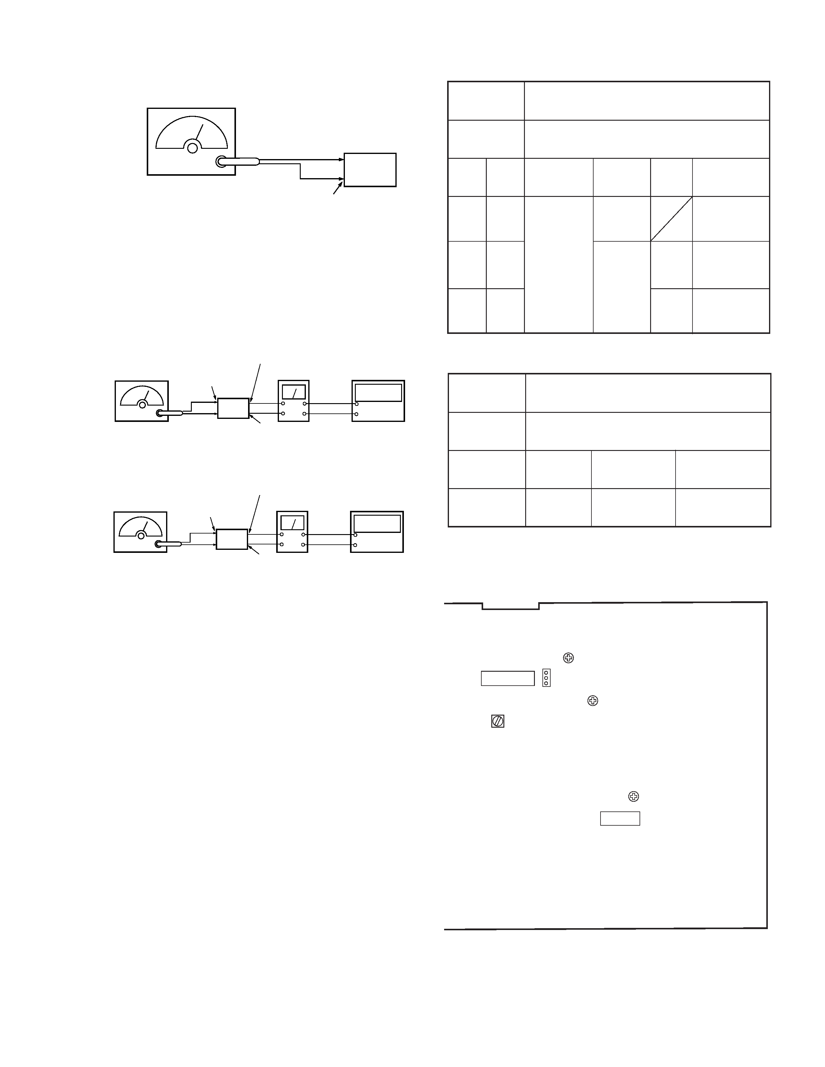
Fig. 1 Subcarrier
Fig. 2 VCO Frequency
Subcarrier/VCO Frequency Adjustment
SWITCH
POSITION
SIGNAL
GENERATOR
STEP
TEST
STAGE
FM TUNING
FREQUENCY
SIGNAL
GENERA-
TOR
AD-
JUST-
MENT
REMARKS
BAND : FM
FM MODE : MONO
70 MHz, 76 dB, FM modulated (MONO SIGNAL)
1
2
3
fo
Q
70 MHz
1 kHz
(40 kHz
dev.)
31.25 kHz
(10 kHz
dev.)
L401
RV401
The value in this
state should be 0
dB (Vo).
Adjust for
maximam
output.
indication is +15
dB against Vo.
VCO Frequency Adjustment
SWITCH
POSITION
SIGNAL
GENERATOR
FM TUNING
FREQUENCY
ADJUSTMENT
REMARKS
FM MODE : STEREO
70 MHz, 76 dB, FM modulated (MONO SIGNAL)
70 MHz
RV402
Adjust for
31.25 kHz ± 50 Hz
Adjustment Location :
[TUNER BOARD] Componet Side
Procedure :
1. Tune the set to 98MHz.
2. Push the DISPLAY button for digital signal meter indication.
3. Adjust RV201 to the place where level and "70dB" indication
lights on fluorescent indicator tube.
Subcarrier/VCO Frequency Adjustment
RV402 VCO
L401
SUBCARRIER
TP401
1
3
IC401
IC201
RV401 SUBCARRIER
RV201
FM SIGNAL LEVEL
FM RF signal
generator
set
FM ANTENNA
75
coaxial
(TM101)
Carrer frequency : 98 MHz
Modulation
: 1 kHz, 40 kHz deviation
Output level
: 6.3 mV (76dB
µ)
(75
open)
FM RF signal
generator
GND
Antenna
TP401-
1 pin
TP401-
2 pin
Level Meter
Frequency
Counter
FM RF signal
generator
GND
Antenna
TP401-
3 pin
TP401-
2 pin
Frequency
Counter
Level Meter