SERVICE MANUAL
FM STEREO, FM/AM
SUPERHETERODYNE TUNER
AEP Model
UK Model
E Model
Australian Model
SPECIFICATIONS
ST-S9
Ver 1.0 2001.09
ST-S9 is the tuner section in
MHC-S9D.
Tuner section
FM stereo, FM/AM superheterodyne tuner
FM tuner section
Tuning range
87.5 108.0 MHz
Antenna
FM lead antenna
Antenna terminals
75 ohm unbalanced
Intermediate frequency
10.7 MHz
AM tuner section
Tuning range
Pan American model:
530 1,710 kHz
(with the interval set at
10 kHz)
531 1,710 kHz
(with the interval set at
9 kHz)
European and Middle Eastern models:
531 1,602 kHz
(with the interval set at
9 kHz)
Other models:
531 1,602 kHz
(with the interval set at
9 kHz)
530 1,710 kHz
(with the interval set at
10 kHz)
Antenna
AM loop antenna
Antenna terminals
External antenna terminal
Intermediate frequency
450 kHz
Dimensions (w/h/d)
Approx. 280 x 108 x 340 mm
Mass
Approx. 2.1 kg
Design and specifications are subject to change
without notice.
9-873-283-01
Sony Corporation
2001I0500-1
Home Audio Company
C
2001.9
Shinagawa Tec Service Manual Production Group
2
ST-S9
TABLE OF CONTENTS
1.
SERVICING NOTES ................................................ 2
2.
GENERAL
Location of Controls .......................................................
3
Setting the Time ..............................................................
4
3.
DISASSEMBLY
3-1. Disassembly Flow ...........................................................
5
3-2. Case .................................................................................
6
3-3. Front Panel Section .........................................................
6
3-4. PANEL Board, SIRCS Board .........................................
7
3-5. Tuner Pack (FM/AM) .....................................................
7
3-6. MAIN Board ...................................................................
8
3-7. DSP Board .......................................................................
8
4.
TEST MODE .............................................................. 9
5.
DIAGRAMS
5-1. Note for Printed Wiring Boards and
Schematic Diagrams ....................................................... 10
5-2. Schematic Diagram MAIN Board (1/2) .................. 12
5-3. Schematic Diagram MAIN Board (2/2) .................. 13
5-4. Printed Wiring Board MAIN Board ........................ 14
5-5. Printed Wiring Board DSP Board ............................ 15
5-6. Schematic Diagram DSP Board (1/2) ..................... 16
5-7. Schematic Diagram DSP Board (2/2) ..................... 17
5-8. Printed Wiring Boards PANEL Section .................. 18
5-9. Schematic Diagram PANEL Section ....................... 19
5-10. IC Pin Function Description ........................................... 20
6.
EXPLODED VIEWS
6-1. Case, Front Panel Section ............................................... 26
6-2. Chassis Section ............................................................... 27
7.
ELECTRICAL PARTS LIST ............................... 28
Notes on chip component replacement
· Never reuse a disconnected chip component.
· Notice that the minus side of a tantalum capacitor may be dam-
aged by heat.
SAFETY-RELATED COMPONENT WARNING!!
COMPONENTS IDENTIFIED BY MARK 0 OR DOTTED
LINE WITH MARK 0 ON THE SCHEMATIC DIAGRAMS
AND IN THE PARTS LIST ARE CRITICAL TO SAFE
OPERATION. REPLACE THESE COMPONENTS WITH
SONY PARTS WHOSE PART NUMBERS APPEAR AS
SHOWN IN THIS MANUAL OR IN SUPPLEMENTS PUB-
LISHED BY SONY.
SECTION 1
SERVICING NOTES
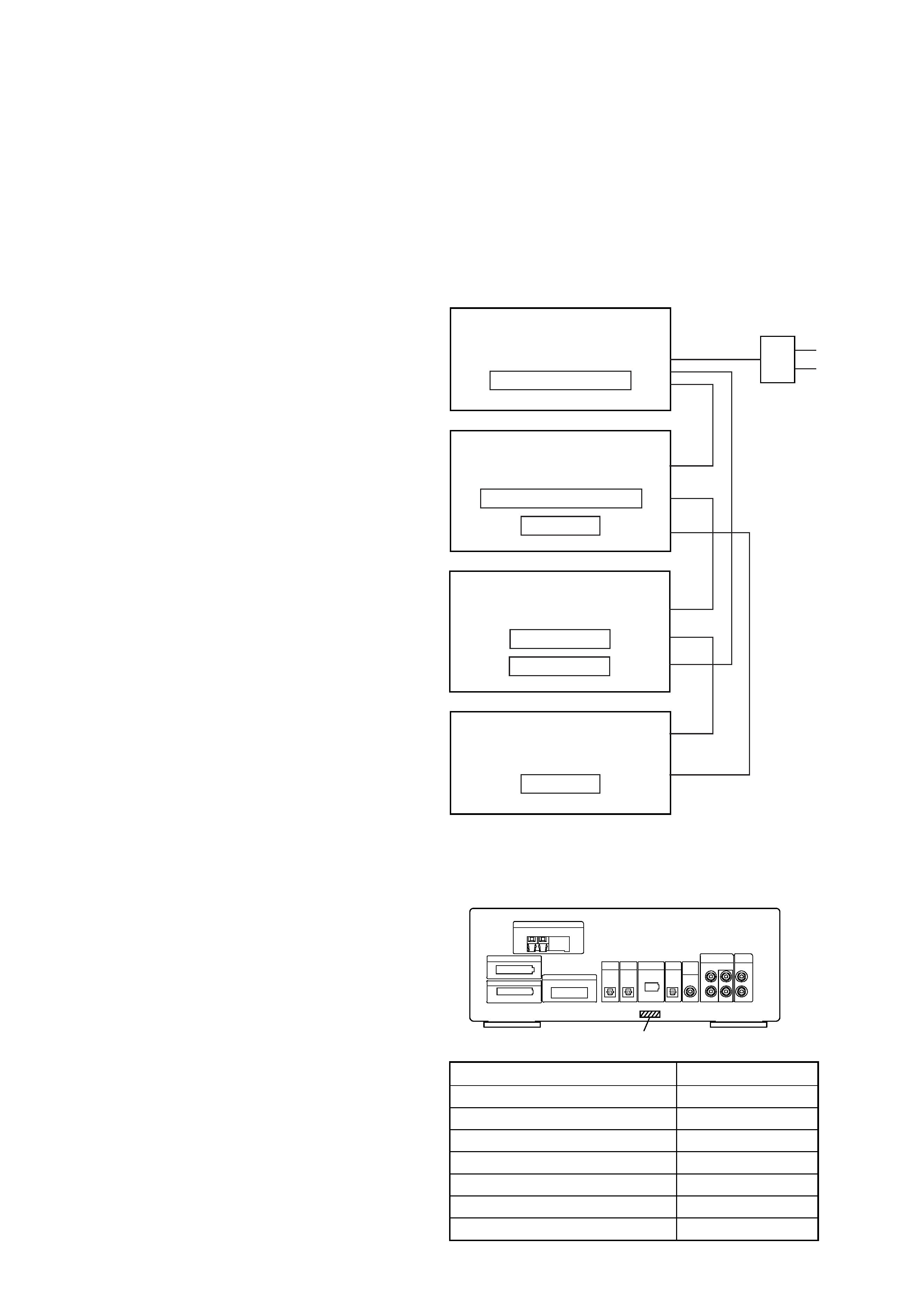
This set is a component of the MHC-S9D.
The MHC-S9D system configuration is as shown below, and there-
fore it does not operate normally unless all four components are
connected.
In performing the repair, connect all components with the system
cables.
Note: The precaution to the users is described on the label stuck
on the back panel (DVD/video CD/CD player) and in the trouble-
shooting section in the Operation Manual.
System Configuration:
POWER SUPPLY
AC IN
TA
MASTER & GRAPHIC
µcon
ST
TC
µcon
TC
DISPLAY
HTC & MB
µcon
DVP
POWER BLOCK
· MODEL IDENTIFICATION
Rear Panel
PART No.
MODEL
PART No.
AEP and UK models
4-232-349-0[]
Australian model
4-232-349-1[]
Saudi Arabia model
4-232-349-2[]
Singapore and E models
4-232-349-3[]
Mexican model
4-232-349-4[]
Thai model
4-232-349-5[]
Korean model
4-232-349-6[]
3
ST-S9
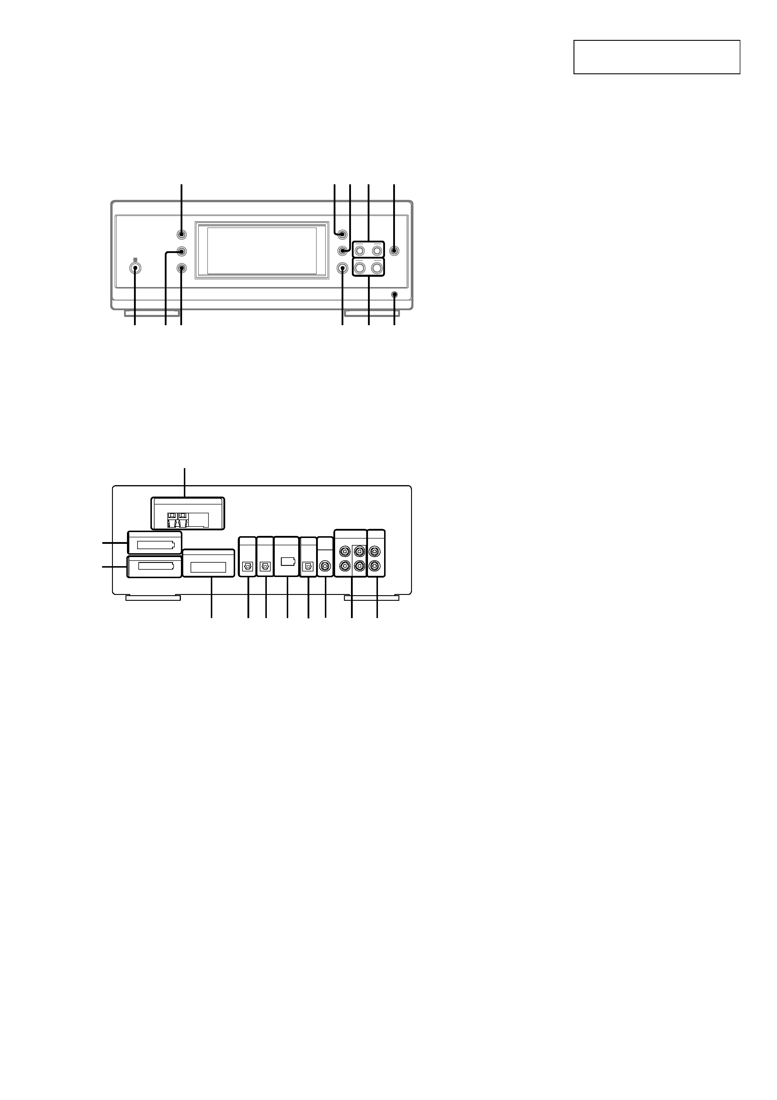
1 ANTENNA terminal
2 SYSTEM CONTROL 1 connector (TO TA-S9D)
3 SYSTEM CONTROL 2 connector (TO TA-S9D)
4 SYSTEM CONTROL 3 connector (FROM DVP-S9)
5 OPTICAL IN terminal
6 OPTICAL IN terminal (FROM DVP-S9)
7 SYSTEM CONTROL 4 connector (TO TC-S9)
8 OPTICAL OUT terminal
9 SUB WOOFER OUT jack
0 MD IN/OUT jack
qa VIDEO (AUDIO) IN jack
Rear Panel
SECTION 2
GENERAL
This section is extracted from
instruction manual.
LOCATION OF CONTROLS
Front Panel
1
2
3
4
5 6 7 8
0
9
qa
CLOCK/TIMER wj (17, 47, 56)
DISPLAY qk (17, 31, 32, 43, 54,
63)
ENTER ws (42, 43)
IR receptor wk
PRESET --/+ wf (42, 43)
PTY (European model only) wd
(43)
STEREO/MONO ql (43, 63)
TIMER SELECT wh (47, 56)
TUNER/BAND wg (42)
TUNER MEMORY w; (42)
TUNING --/+ wa (42)
--
--
+
+
qk
qlw; wa
ws
wf
wg
wd
wh
wj
wk
4
ST-S9
Setting the time
1 Turn on the system.
2 Press CLOCK/TIMER (or CLOCK/TIMER
SET on the remote).
When you set the time for the first time,
proceed to step 5.
3 Press O or o repeatedly to select
"CLOCK SET".
4 Press ENTER (A/V amplifier or remote).
5 Press O or o repeatedly to set the hour.
6 Press ENTER (A/V amplifier or remote).
7 Press O or o repeatedly to set the
minutes.
8 Press ENTER (A/V amplifier or remote).
Tip
If you have made a mistake or want to change the
time, start over from step 2.
Note
The clock settings are canceled when you disconnect
the power cord or if a power failure occurs.
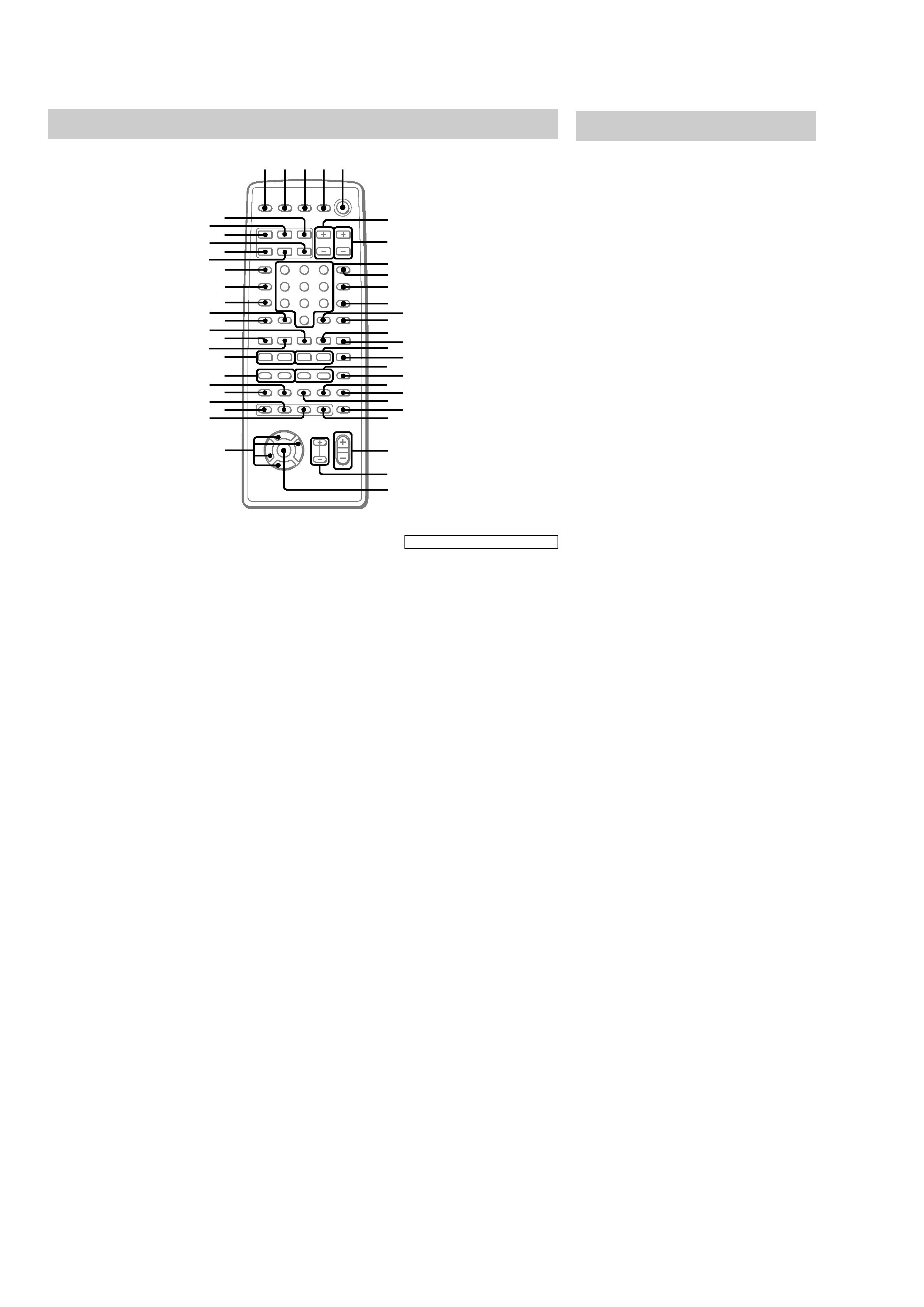
Remote control
ANGLE es (37)
AUDIO ws (34)
CLEAR qs (22, 29, 30, 36)
CLOCK/TIMER SELECT 3
(47, 56)
CLOCK/TIMER SET 2 (17, 47,
56)
DBFB ra (48)
D.SKIP 9 (26)
DIGITAL rf (57)
DISPLAY rj (17, 31, 32, 43, 54)
DVD DISPLAY wd (18, 19, 30,
32--34, 36--40)
DVD MENU wa (27)
DVD SET UP ql (18, 19, 24, 39)
ENTER wj
EQ ea (52)
EQ ON/OFF wl (53)
FILE SELECT +/-- wh (48, 49,
53)
FUNCTION rd (18, 25, 27, 28,
36, 45, 46, 55, 57)
GROOVE rs (48)
KARAOKE PON (Except for
North American and European
models) el (54)
MD rh (57)
Numeric buttons 8 (28, 30)
PLAY MODE qa (25, 28, 29, 46)
REPEAT q; (30)
RETURN
O qd (27, 39, 40)
SELECT DVD
N eh (20, 25,
27, 29, 30)
SET UP wf (14, 16, 51, 53, 54)
SLEEP 1 (55)
SLOW
t/T qk (26)
SPECTRUM ANALYZER rk
(54)
STEP
c/C ef (26)
SUBTITLE ed (37)
SUR e; (51)
TAPE A
nN ek (44)
TAPE B
nN qf (44, 45)
TITLE w; (27)
TUNER/BAND ej (42)
TV
@/1 4 (13)
TV CH +/-- 7 (13)
TV/VIDEO rl (13)
TV VOL +/-- 6 (13)
VIDEO rg (57)
VOL +/-- wg
x
M
m
>
.
nN
O
X
T
t
C
c
V
v
Bb
12 3 4 5
e;
es
ef
ej
eg
6
7
9
8
q;
qa
qd
qs
qf
qg
qj
qh
qk
ql
wa
wd
ws
wf
w;
wg
wj
wh
wk
ed
wl
ea
eh
el
rs
ra
rd
ek
r;
rg
rj
rl
rf
rh
rk
BUTTON DESCRIPTIONS
@/1 (power) 5
X (pause) qj
x (stop) qg
m/M (rewind/fast forward),
TUNING --/+ qh
./> (go back/go forward),
PRESET --/+, PREV/NEXT eg
O/o/P/p wk
>10 r;
5
ST-S9
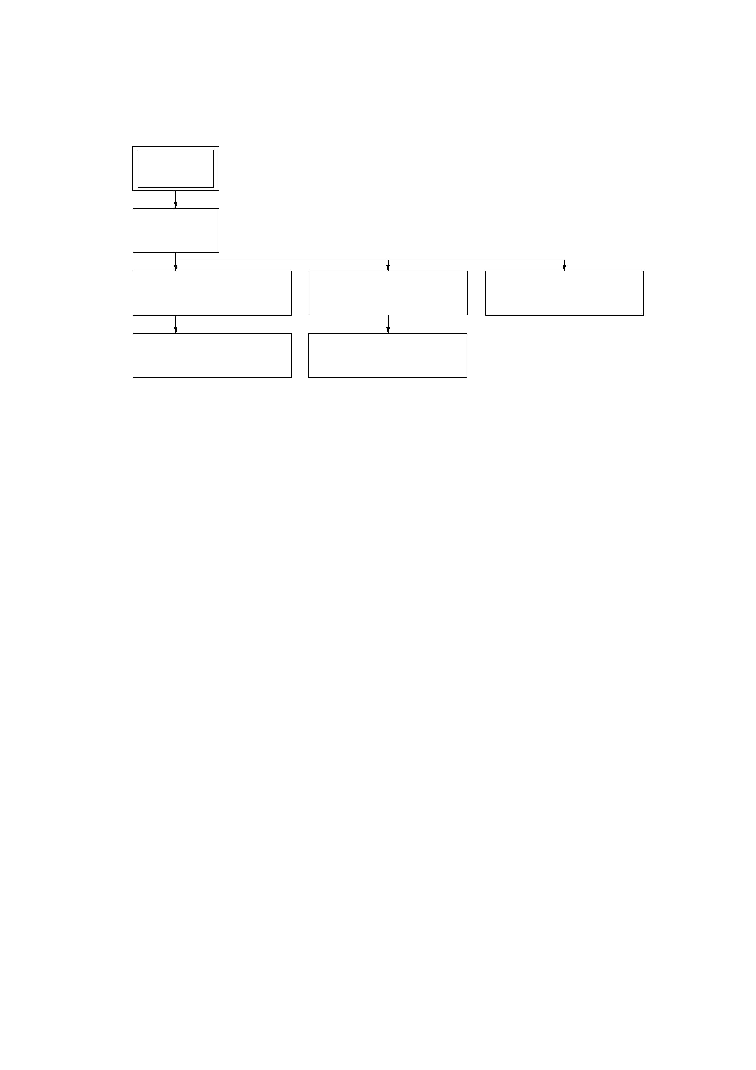
· This set can be disassembled in the order shown below.
3-1.
DISASSEMBLY FLOW
SECTION 3
DISASSEMBLY
3-2. CASE
(Page 6)
3-3. FRONT PANEL SECTION
(Page 6)
3-4. PANEL BOARD,
SIRCS BOARD
(Page 7)
3-7. DSP BOARD
(Page 8)
3-5. TUNER PACK (FM/AM)
(Page 7)
3-6. MAIN BOARD
(Page 8)
SET