-- 1 --
AEP Model
SPECIFICATIONS
MICROFILM
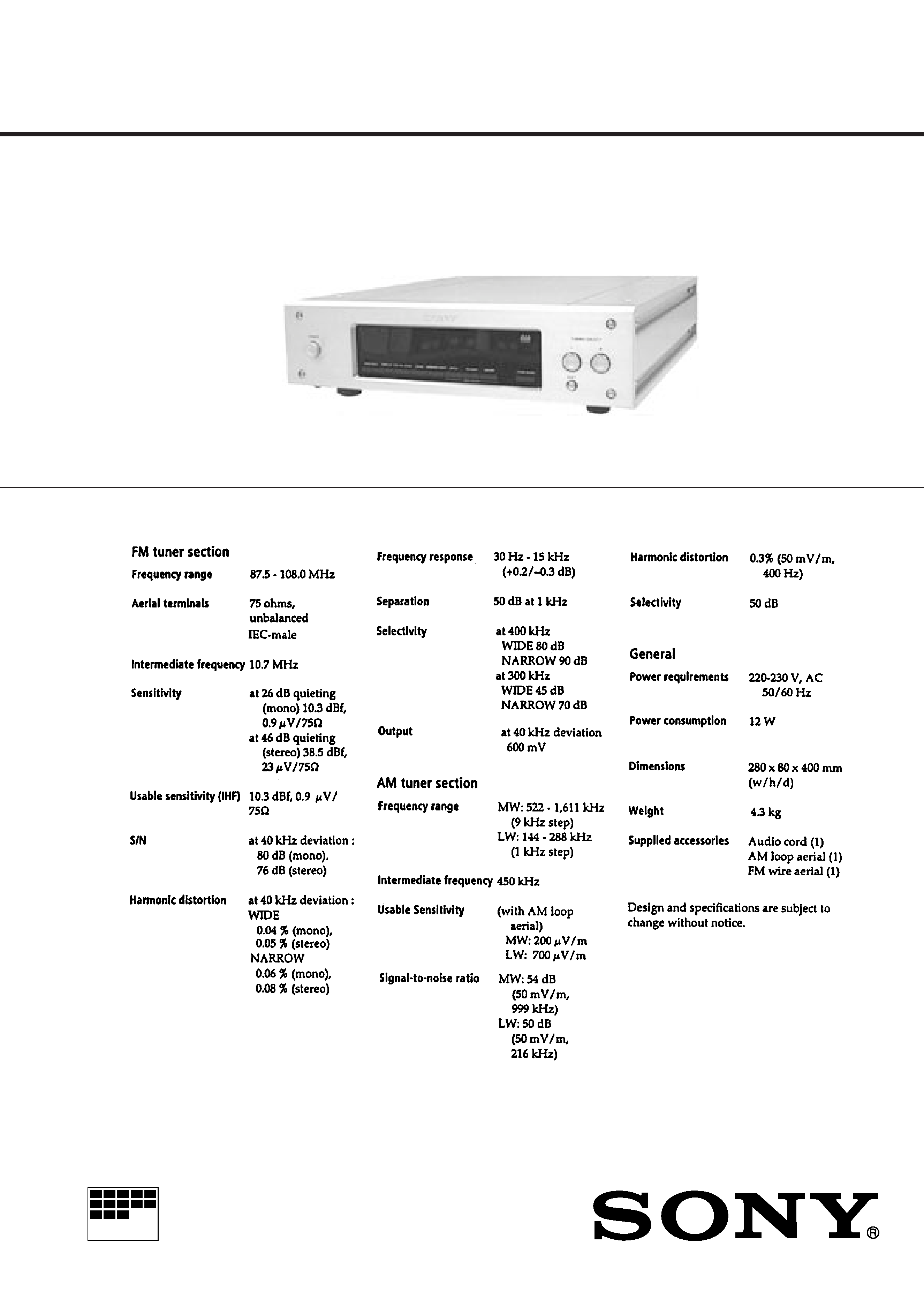
FM STEREO FM-AM TUNER
ST-S3000ES
SERVICE MANUAL
-- 2 --
SECTION 1
GENERAL
TABLE OF CONTENTS
1. GENERAL ................................................................... 2
2. TEST MODE ................................................................ 3
3. ELECTRICAL ADJUSTMENT ..................................... 4
4. DIAGRAMS
4-1.
Waveforms .......................................................................... 7
4-2.
IC Block Diagrams ............................................................. 8
4-3.
Schematic Diagram -- Main Section -- ............................ 9
4-4.
Printed Wiring Board -- Main Section -- ....................... 13
4-5.
Printed Wiring Board -- Power Board Section -- ........... 15
4-6.
Schematic Diagram -- Power Board Section -- ............. 16
4-7.
Printed Wiring Board -- Display Section -- ................... 17
4-8.
Schematic Diagram -- Display Section -- ...................... 19
4-9.
IC Pin Function
· IC701 System Control (µPD780205GF) ....................... 21
5. EXPLODED VIEW .................................................... 23
6. ELECTRICAL PARTS LIST .................................... 24
SAFETY-RELATED COMPONENT WARNING !!
COMPONENTS IDENTIFIED BY MARK
! OR DOTTED LINE
WITH MARK
! ON THE SCHEMATIC DIAGRAMS AND IN
THE PARTS LIST ARE CRITICAL TO SAFE OPERATION.
REPLACE THESE COMPONENTS WITH SONY PARTS
WHOSE PART NUMBERS APPEAR AS SHOWN IN THIS
MANUAL OR IN SUPPLEMENTS PUBLISHED BY SONY.
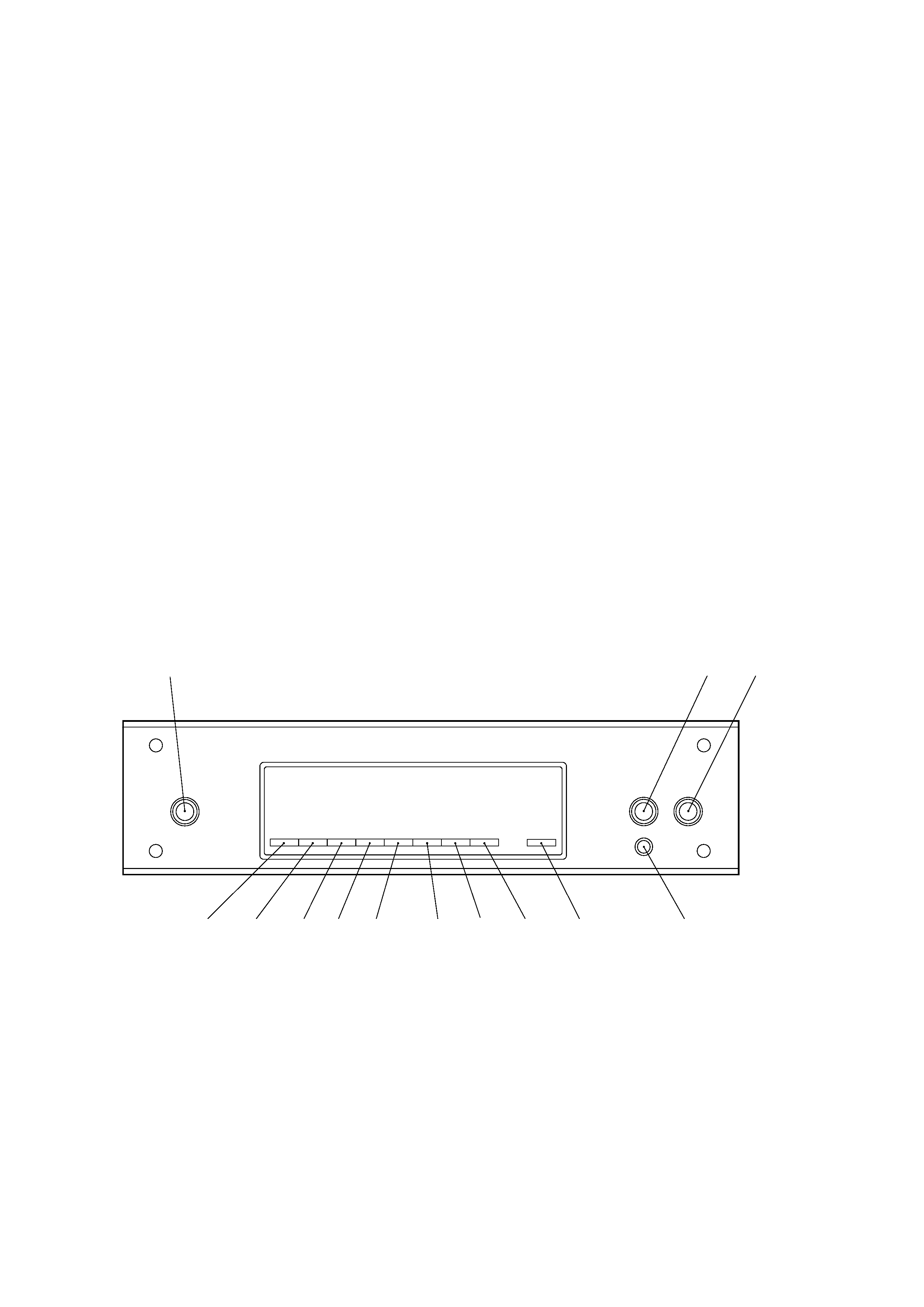
Location of Parts and Controls
4
56
7
8
10
911
12
13
1
3
2
1 POWER button
2 TUNING/SELECT button
3 TUNING/SELECT+ button
4 DISPLAY button
5 CHARACTER button
6 ANTENNA button
7 BAND button
8 MEMORY button
9 MENU ENTRY MENU button
10 MENU ENTRY RETURN button
11 MENU ENTRY ENTER button
12 TUNE MODE button
13 SHIFT button
-- 3 --
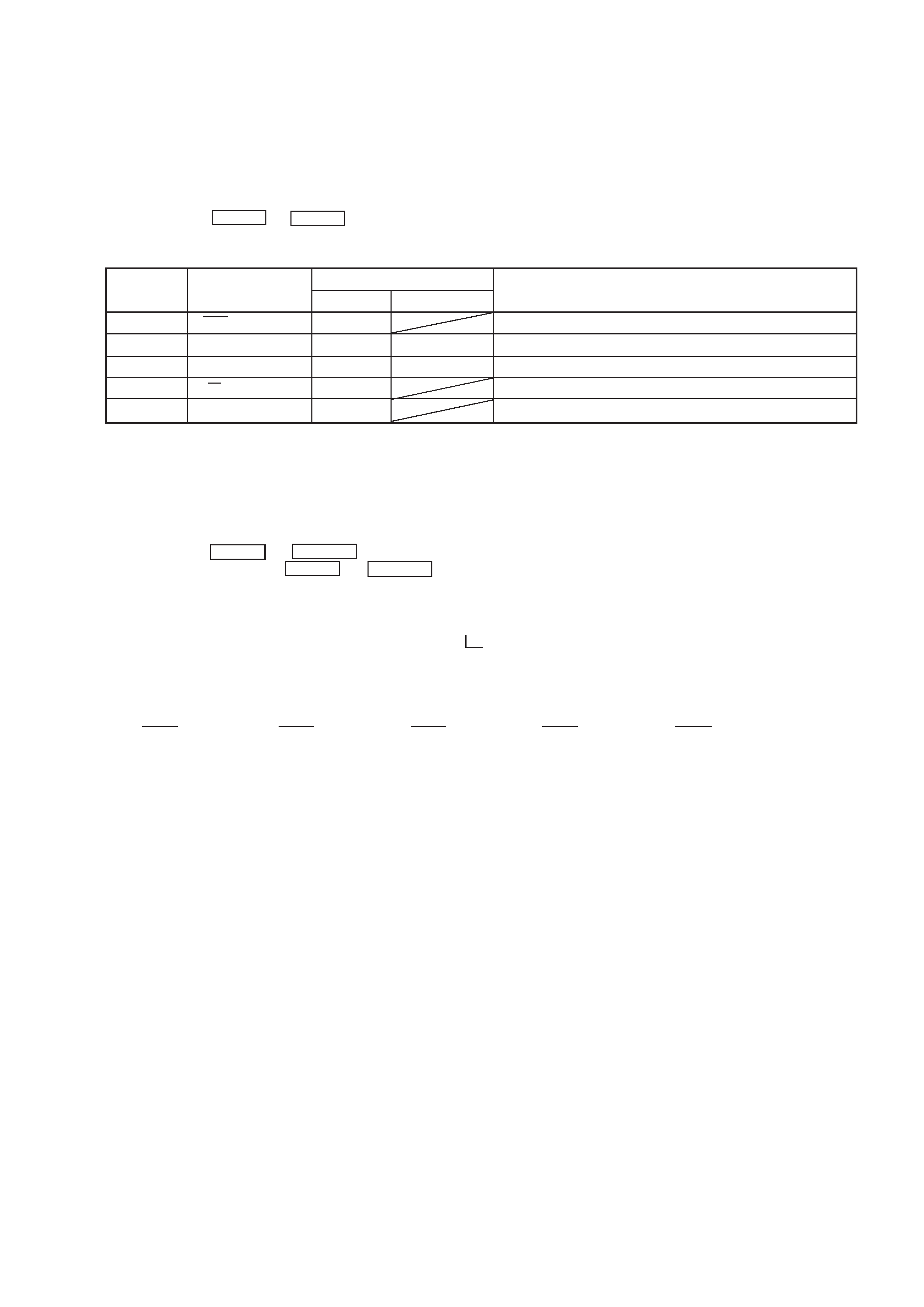
1. Circuit Check Mode
Set to the reception frequency that the circuit can STEREO RDS stations. (Set the input level to above 70 dB.)
This enables circuit check to be performed in any of the reception modes-FM, AM (MW, LW). Set to a desired band before setting the test
mode.
1. Turn OFF the power.
2. While pressing ENTER and BAND together, turn ON the power.
· The items in the following table will be checked automatically in order every 2 seconds.
SECTION 2
TEST MODE
Tuned
IF Frq
Sig Level
Stereo
RDS Signal
AST signal =LOW
IF COUNT OK
SI LEVELh70dB
ST signal=LOW
RDS DATA OK
OK or NG
OK or NG
OK or NG
OK or NG
OK or NG
OK or NG
OK or NG
IC251 NG, RV251 adjustments
FE101, IC251 NG, or IF count buffer amp (Q251, Q401) NG
IC221 NG, RV221 adjustments
IC301 NG, RV301 adjustments
IC801 NG
NG
Display
Items
FM RDS
AM (MW, LW)
DISPLAY
NOTE : The preset data will be erased when this test mode is used. Therefore, take down the data before setting this mode and preset the data
again after completing operations in this mode.
2. FLUORESCENT INDICATOR TUBE Check and KEY Check mode
1. Turn OFF the power.
2. While pressing ENTER and RETURN together, turn ON the power.
3. While continuously pressing ENTER and RETURN together, check the following.
Indication test pattern
* The indication test patterns from 2 to 5 are indicated on only even grids.
The display changes every 1 sec.
1 7F
p p p p p
p p p p p
p p p p p
p p p p p
p p p p p
p p p p p
p p p p p
2 60
p p
p p
p p
p p
p p
p p
p p
3 7E
p p p p p
4 3D
p p p p p
p p p p p
5 5F
p p p p p
Microcomputer version indication (1 sec)
n All light up "7F" n Dot area only "60" n Dot area only "7E"
Dot area only "5F"
N Dot area only "3D"
N
N
-- 4 --
4. Release ENTER and RETURN . The KEY CHECK mode will be set.
5. All key numbers will be displayed.
Key Number : 12
6. Each time the key is pressed, the key number will be counted down.
Each key will be counted only once, at the first time.
7. When all keys have been pressed, the process will end.
NOTE : As contents of the Factory Preset will be written into memory after completing this check mode, delete contents of memory
according to 4. Forced RESET.
3. Entering the Factory Preset (In case perform just to write memory of the Factory Preset.)
1. Turn OFF the power.
2. While pressing ENTER and MEMORY together, turn ON the power.
4. Forced RESET (Used to delete the contents of Factory Preset when it is written into the preset memory.)
Clears all the RAMs and sets the initial state
1. Turn OFF the power.
2. While pressing ENTER and ANTENNA together, turn ON the power.
3. When "All clear" is indicated on the display tube.
SECTION 3
ELECTRICAL ADJUSTMENTS
Precautions in Repairing
If the front end unit fails, it is difficult to repair the inner circuits, so
replace the entire front end unit.
Set "IF : WIDE" after the all adjustments.
FM SECTION
0dB = 1µV
· Standard Setting of FM Stereo RF Signal Generator.
STEREO STANDARD SIGNAL
MONAURAL
STANDARD SIGNAL
Carrier frequency
: 98MHz
Modulation
: Audio 1kHz
Main channel (L+R) :33.75kHz
deviation
Sub channel (LR)
:33.75kHz
deviation
Pilot
:7.5kHz
deviation
Carrier frequency
: 98MHz
Modulation : Audio 1kHz
75kHz deviation
FM RF SSG
1 kHz
highpass
filter
distortion meter
FM ANTENNA (75
)
LINE OUT
set
How to switch IF BAND : WIDE/NARROW and ANT ATT :
ON/OFF
Method:
1. Press the power button to turn the power on and set to FM.
2. Press the MENU button and press the TUNING/SELECT , +
button to indicate "Reception" on the fluorescent display tube,
then press the ENTER button.
3. Press the TUNING/SELECT , + button to indicate "ATT/IF
Band", and press the ENTER button.
4. "ANT ATT: OFF" is indicated on the fluorescent display tube
and press the TUNING/SELECT , + button to indicate "ON"
or "OFF", then press the ENTER button.
When the ANT ATT is set, "ANT ATT" is indicated on the fluo-
rescent display tube.
5. "IF: Wide" is indicated on the fluorescent display tube, and press
the TUNING/SELECT , + button to indicate "Wide" or "Nar-
row", then press the ENTER button.
When the "IF: Narrow" is set, "NARROW" is indicated on the
fluorescent display tube.
6. Set WIDE after the operation.
-- 5 --
FM Discriminator ADJUSTMENT
(NULL and MONO Distortion Adjustment)
Setting :
IF BAND : WIDE
ANT ATT : OFF
FM RF SSG
1 kHz
highpass
filter
distortion meter
FM ANTENNA (75
)
LINE OUT
Modulation: Monaural Standard signal
Output level: 6mV (76dB) (at 75
open)
Procedure :
1. Tune the set to 98 MHz.
2. Adjust IFT252 for 0V reading on the digital voltmeter.
.................. NULL
3. Adjust IFT253 for a minimum reading on the distortion meter.
.................. MONO Distortion (THD)
4. Repeat the adjustments of 2 and 3 several times.
Note : When replacing the ceramic filter, perform this alignment.
TP251
NULL terminal
Digital Voltmeter
(DC range)
set
Stereo Level Adjustment
Setting :
IF BAND : WIDE
ANT ATT : OFF
FM RF SSG
set
FM ANTENNA (75
)
Modulation: Stereo Standard signal
Output level: 18µV (25dB) (at 75
open)
Procedure :
1. Tune the set to 98 MHz.
2. Adjust RV251 to the point (moment) when the "STEREO"
indicator will change from going off to going on.
FM RF SSG
set
FM ANTENNA (75
)
Modulation: Stereo Standard signal
Output level: 18µV (25dB) (at 75
open)
Narrow Gain Adjustment
Setting :
IF BAND : NARROW
ANT ATT : OFF
Procedure :
1. Tune the set to 98 MHz.
2. Set "IF BAND : NARROW" according to the procedure of "How
to switch IF BAND WIDE/NARROW" on page 6.
3. Adjust RV231 to the point (moment) when the "STEREO" indi-
cator will change from going off to going on.
FM Meter Level Adjustment
Setting :
IF BAND : WIDE
ANT ATT : OFF
FM RF SSG
FM ANTENNA (75
)
Modulation: Stereo Standard signal
Output level: 3mV (76dB) (at 75
open)
Procedure :
1. Tune the set to 98 MHz.
2. Press DISPLAY button to display the digital signal, then adjust
RV221 to be displayed as "SIG 70dB".
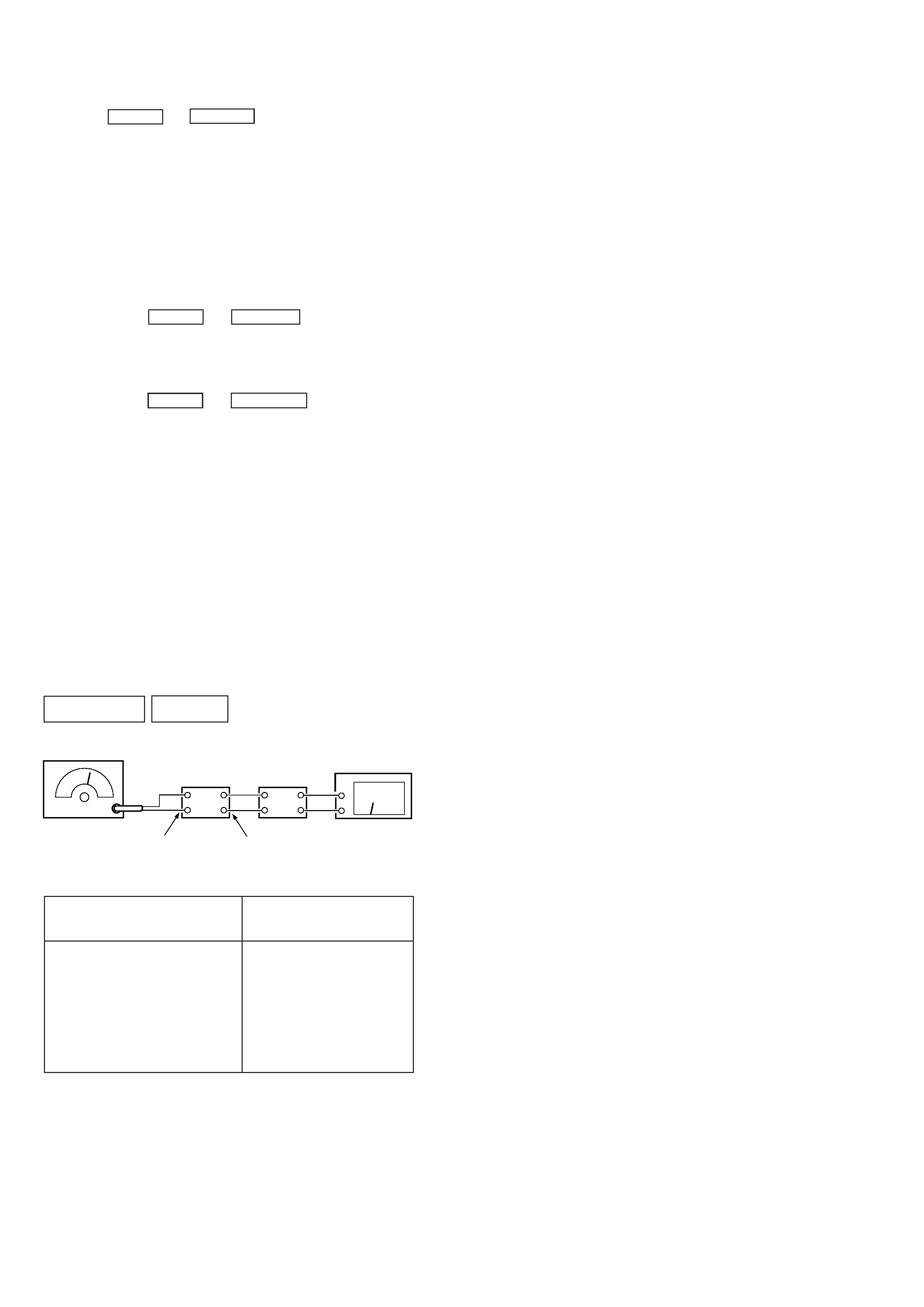
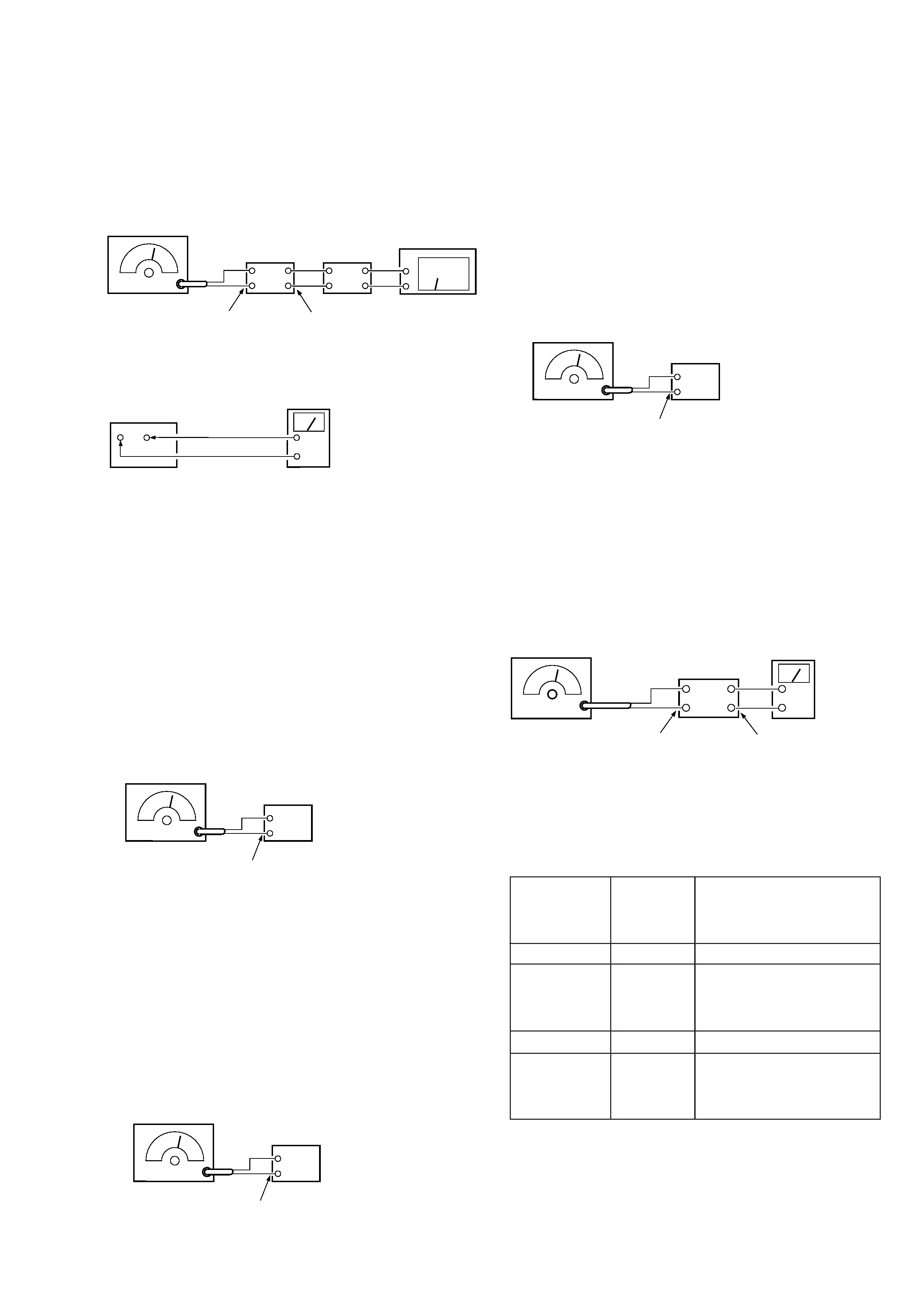
Stereo Separation Adjustment
Setting :
IF BAND : WIDE
set
FM RF SSG
FM ANTENNA (75
)
set
LINE OUT
level meter
Modulation: Stereo Standard signal
Output level: 6mV (76dB) (at 75
open)
Procedure :
1. Refer to "How to switch IF BAND WIDE/NARROW" on page
6.
FM stereo
Signal generator
Output channel
Level meter
connection
Level meter
reading (dB)
L-CH
L-CH
A
B
Adjust RV301 for minimum
reading on Level meter
R-CH
L-CH
R-CH
R-CH
C
D
Adjust RV301 for minimum
reading on Level meter
L-CH
R-CH
L-CH Stereo separation : A - B
R-CH Stereo separation : C - D
The separations of both channels should be equal.