STR-WX7
E Model
Australian Model
SERVICE MANUAL
FM STEREO/FM-AM RECEIVER
MICROFILM
SPECIFICATIONS
STR-WX7 is the tuner and amplifier
section in MHC-WX7AV.
Amplifier section
The following measured at AC 120, 220, 240 V 50/60 Hz
DIN power output (Rated) (FRONT)
120 + 120W (6
at 1kHz DIN)
Continuous RMS power output (Reference)
FRONT SPEAKER: 150 + 150W
(6
at 1kHz, 10% THD)
CENTER SPEAKER: 60W
(8
at 1kHz, 10% THD)
REAR SPEAKER: 40 + 40W
(8
at 1kHz, 10% THD)
Inputs
MD/VIDEO 1 IN (phono jacks): voltage
450/250mV, impedance 47k
AV INPUT AUDIO (phono jacks):
voltage 250mV, impedance 47k
MIX MIC (phone jack): sensitivity 1mV,
impedance 10k
Output
MD/VIDEO 1 OUT (phono jacks):
voltage 450/250mV, impedance 1k
PHONES (stereo phone jack): accepts
headphones of 8
or more.
FRONT SPEAKER:
accepts impedance of 6 to 16
CENTER SPEAKER:
accepts impedance of 8 to 16
REAR SPEAKER:
accepts impedance of 8 to 16
SUPER WOOFER:
Voltage 1V, impedance 1k
Video section
Inputs
AV INPUT VIDEO (phone jack): 1Vp-p,
75
Outputs
MONITOR OUT (phone jack): 1Vp-p,
75
5Tuner section
FM stereo, FM/AM superheterodyne tuner
FM tuner section
Tuning range
87.5 108.0MHz
Antenna terminals
75
unbalanced
Intermediate frequency
10.7MHz
AM tuner section
Tuning range
Middle Easten models:
531 1,602kHz(with the MW interval set at
9kHz)
5.95 17.90MHz (with the SW interval set
at 5kHz)
Australian, Thai models : 531 1,602kHz(with the AM tuning
interval set at 9kHz)
530 1,710kHz (with the AM tuning
interval set at 10kHz)
Other models:
MW :
531 1,602kHz(with the MW tuning
interval set at 9kHz)
530 1,710kHz (with the MW tuning
interval set at 10kHz)
SW :
5.95 17.90 MHz (with the SW tuning
interval set at 5kHz)
Intermediate frequency
450kHz
Antenna
AM loop antenna
External antenna terminal
-- Continued on next page --

2
TABLE OF CONTENTS
1. GENERAL ........................................................................... 3
2. DISASSEMBLY
2-1.
Slideng Panel Assembly ····················································· 4
2-2.
Level Slider ········································································ 4
3. SERVICE MODE .............................................................. 5
4. DIAGRAMS
4-1.
Circuit Boards Location ·················································· 9
4-2.
Block Diagrams
· Main Section ································································ 10
· Power Section ······························································ 11
4-3.
Printed Wiring Board
Main Section ························· 12
4-4.
Schematic Diagram
Main (1/2) Section ···················· 13
4-5.
Schematic Diagram Main (2/2) Section ························· 14
4-6.
Schematic Diagram AV/Mic Section ······························ 15
4-7.
Printed Wiring Board AV/Mic Section ··························· 15
4-8.
Schematic Diagram Power Amp Section ······················· 16
4-9.
Printed Wiring Board Power Amp Section ····················· 17
4-10. Schematic Diagram Display Section ······························ 18
4-11. Printed Wiring Board Display Section ··························· 19
4-12. Schematic Diagram Sliding Panel Section ····················· 20
4-13. Printed Wiring Board Sliding Panel Section ·················· 21
4-14. Schematic Diagram Surround Section ··························· 22
4-15. Printed Wiring Board Surround Section ························· 23
4-16. Printed Wiring Board Trans Section ······························· 24
4-17. Schematic Diagram Trans Section ································· 25
4-18. IC Block Diagrams ··························································· 26
4-19. IC Pin Function ································································ 28
5. EXPLODED VIEWS
6-1.
Case and Sliding Panel Section ........................................ 31
6-2.
Front Panel Section .......................................................... 32
6-3.
Slide Mechanism Section ................................................. 33
6-4.
Circuit Boards and Back Panel Section ............................ 34
7. ELECTRICAL PARTS LIST ........................................ 35
LABEL MODEL NUMBER
No.
MODEL IDENTIFICATION
-- BACK PANEL --
Saudi Arabia, Singapore,
Malaysia, Australian model
4-900-848-2
Thai model
4-900-848-3
MODEL
PART No.
SAFETY-RELATED COMPONENT WARNING!!
COMPONENTS IDENTIFIED BY MARK
! OR DOTTED LINE WITH
MARK
! ON THE SCHEMATIC DIAGRAMS AND IN THE PARTS
LIST ARE CRITICAL TO SAFE OPERATION. REPLACE THESE
COMPONENTS WITH SONY PARTS WHOSE PART NUMBERS
APPEAR AS SHOWN IN THIS MANUAL OR IN SUPPLEMENTS
PUBLISHED BY SONY.
General
Power requirements
Australian model:
240V AC, 50/60Hz
Thailand model:
220V AC, 50/60Hz
Other models:
120V or 220V or 230 240, 50/60Hz
Adjustable with voltage selector
Power consumption
340W
Dimensions (w/h/d)
Approx. 288
× 205 × 375mm
Mass
Approx. 8.8kg
Design and specifications are subject to change without notice.
3
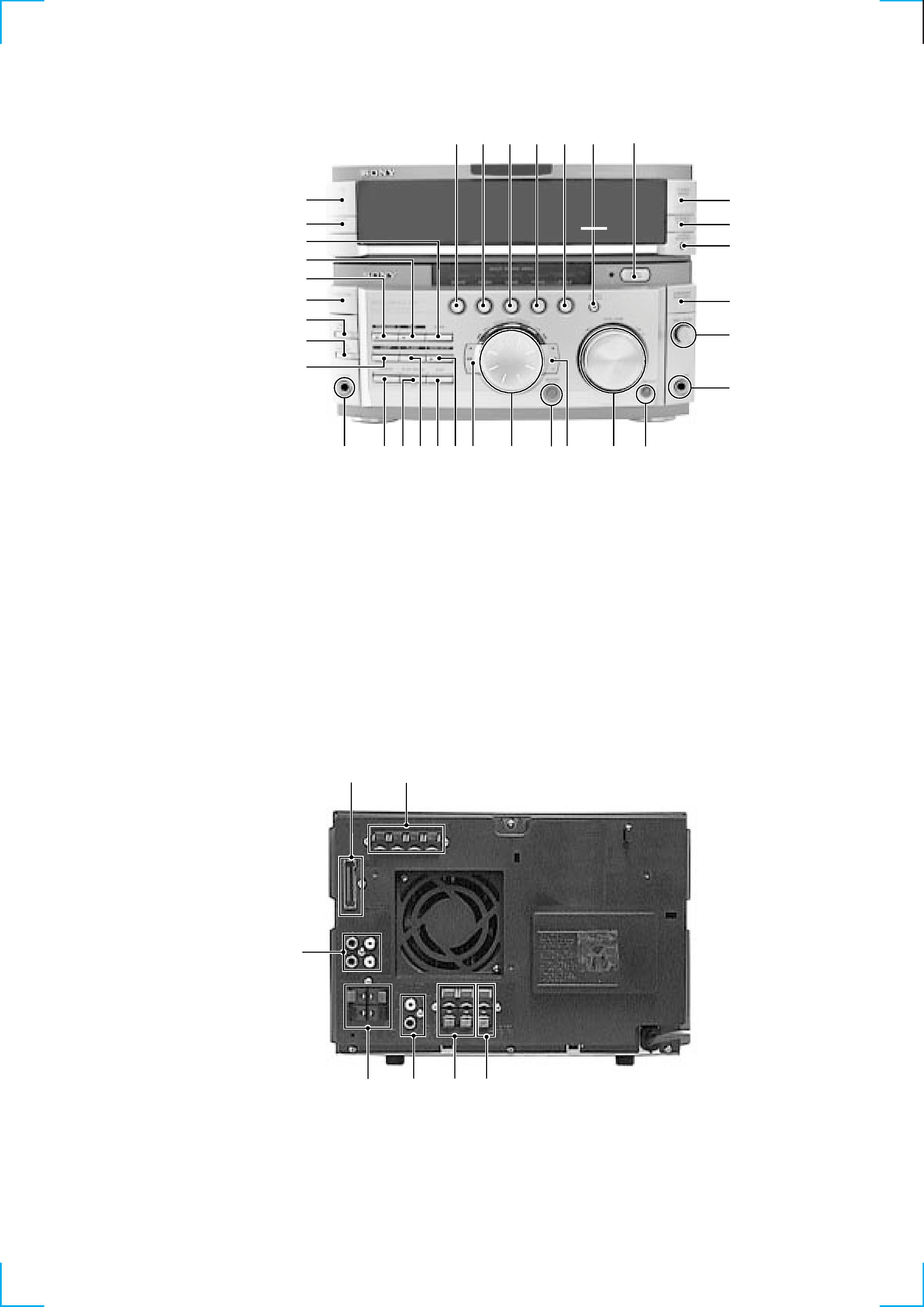
Front Panel
SECTION 1
GENERAL
1 2 3 4 5 6
7
8
9
!º
!¡
!TM
!£
!¢
!
!¶!§
@
@§
@¶
@·
@ª
#£
#¢
#º
!·
!ª
@¡
@£
@¢
@º
#¡
#TM
@TM
Rear Panel
2
4
5
3
1
6
7
1 MOVIE button
2 MUSIC button
3 GAME button
4 PLACE button
5 P FILE button
6 EFFECT ON/OFF button
7 OPEN/CLOSE button
8 TUNER BAND button
9 STEREO/MONO button
!º TUNING MEMORY button
!¡ KARAOKE PON/MPX button
!TM MIC LEVEL dial
!£ MIX MIC jack
!¢ GROOVE button
! VOLUME dial
!§ ) + button
!¶ ENTER/NEXT button
!· MULTI JOG STATION dial
!ª 0 button
@º NON-STOP button
@¡ EDIT button
@TM FLASH button
@£ PLAY MODE button
@¢ REPEAT button
@ PHONES jack
@§ LOOP button
@¶ CLOCK/TIMER SET button
@· TIMER SELECT button
@ª FUNCTION button
#º PROLOGIC button
#¡ DSP button
#TM DBFB button
#£ DISPLAY/DEMO button
#¢ I/u (POWER) button
1 SYSTEM CONTROL jack
2 ANTENNA terminal
3 CENTER SPEAKER terminal
4 REAR SPEAKER terminal
5 MONITOR OUT jack
6 FRONT SPEAKER terminal
7 MD/VIDEO 1 jack
4
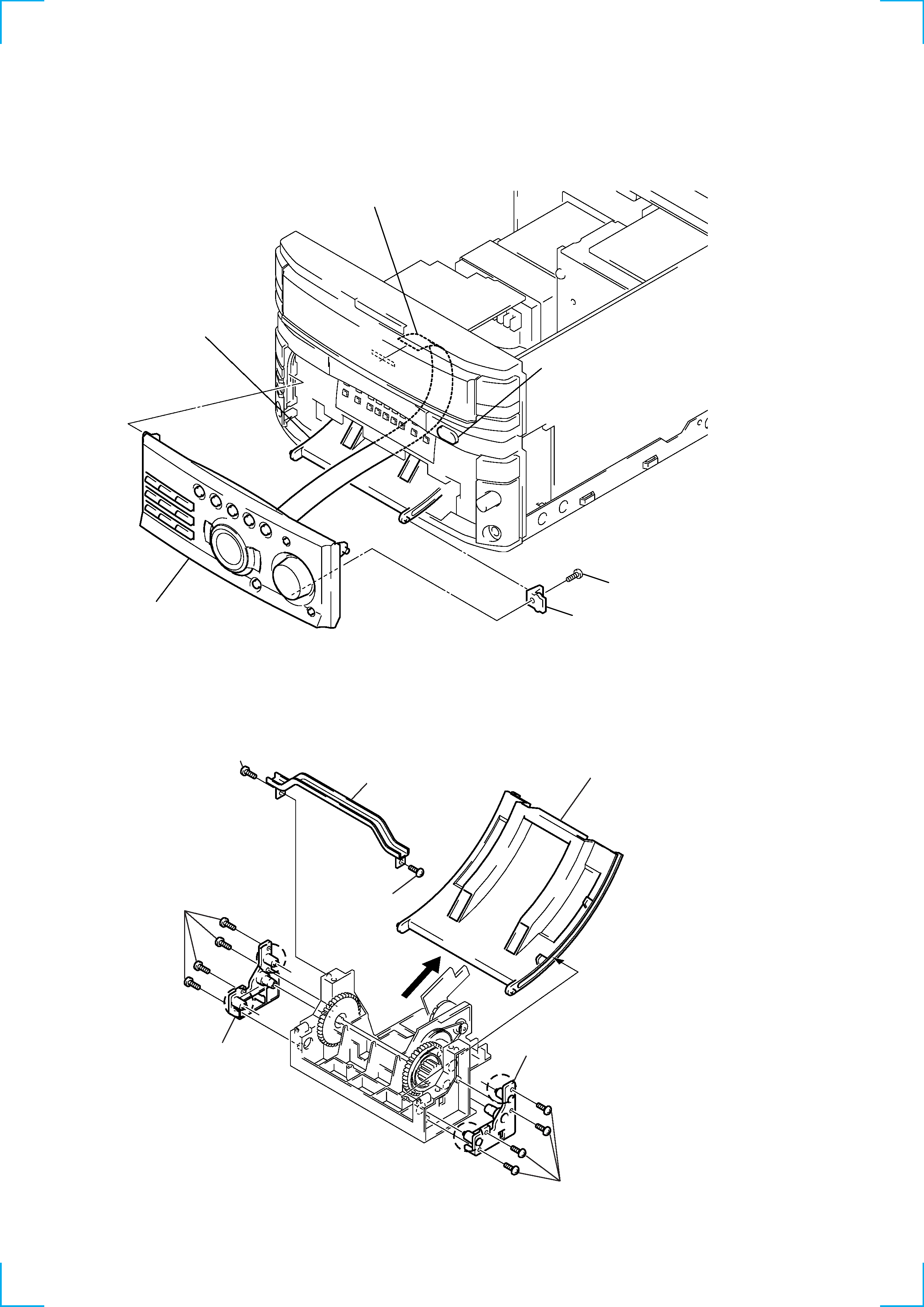
SECTION 2
DISASSEMBLY
Note: Follow the disassembly procedure in the numerical order given.
2-1. SLIDING PANEL ASSEMBLY
4 Flat type cable (19 core)
2 Screw (BVTP 3x8)
3 Holder level
5 Sliding panel assembly
Slide mechanism
1 Push the OPEN/CLOSE button to
open the Sliding panel assembly.
1 Screw (BVTP2.6x8)
4 Four screw
(BVTP2.6x8)
5 Holder (L) assembly
a
a
b
b
6 Four screw (BVTP2.6x8)
7 Holder (R) assembly
8 Remove the Level slider direction of arrow.
2 Screw
(BVTP2.6x8)
3 Top bracket
2-2. LEVEL SLIDER
NOTE FOR INSTALLATION :
Attach in the reverse order, but make sure the rollers (
a, b) of the
holder (L) assembly and holder (R) assembly fit into the grooves of
the level slider.
5
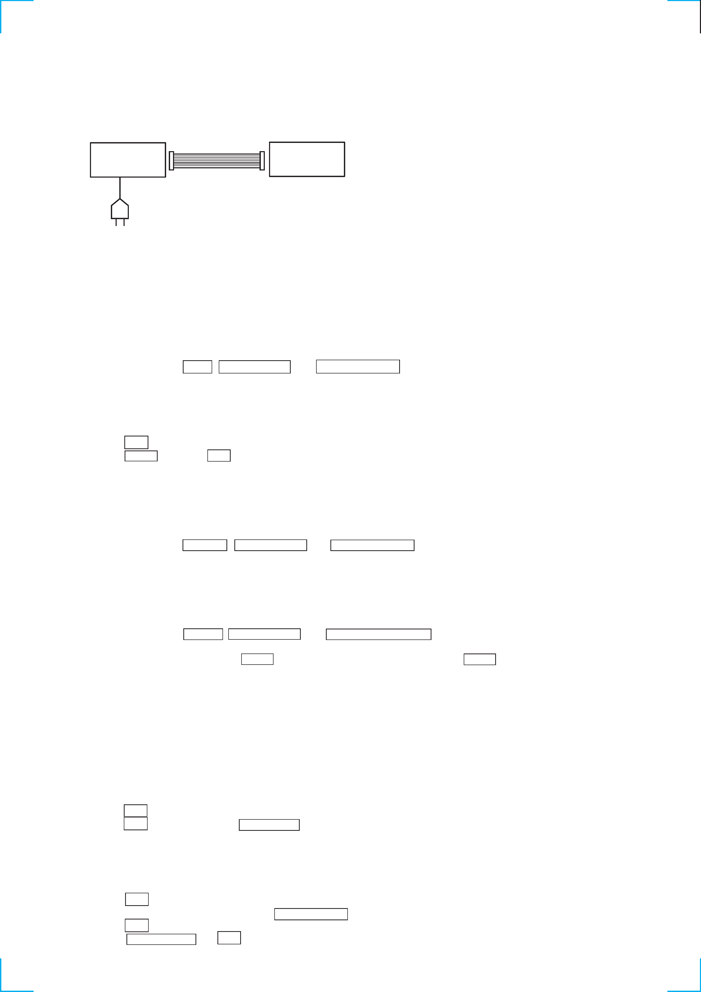
SECTION 3
SERVICE MODE
Connections and Operations When Used Alone
Normally, use the unit connected to the HTC-WX5 as follows.
Basically, when servicing the unit, connect the unit as follows.
Even when not connected to the HTC-WX5, the unit can operate alone as it mounts a power supply (some functions will however not be
available).
MC Cold Reset
· The cold reset clears all data including preset data stored in the RAM to initial conditions. Execute this mode when returning the set to the
customer.
Procedure:
1.
Press three buttons EDIT , ENTER/NEXT , and DISPLAY/DEMO simultaneously.
2.
The fluorescent indicator tube becomes blink instantaneously, and the set is reset.
CD Delivery Mode (This mode can be used only when the HTC-WX5 is connected.)
· This mode moves the pick-up to the position durable to vibration. Use this mode when returning the set to the customer after repair.
Procedure:
1.
Press
1/u button to turn the set ON.
2.
Press LOOP button and
1/u button simultaneously.
3.
A message "LOCK" is displayed on the fluorescent indicator tube, and the CD delivery mode is set.
MC Hot Reset
· This mode resets the set with the preset data kept stored in the memory. The hot reset mode functions same as if the power cord is plugged
in and out.
Procedure:
1.
Press three buttons REPEAT , ENTER/NEXT , and DISPLAY/DEMO simultaneously.
2.
The fluorescent indicator tube becomes blink instantaneously, and the set is reset.
Sled Servo Mode (This mode can be used only when the HTC-WX5 is connected.)
· This mode can run the CD sled motor freely. Use this mode, for instance, when cleaning the pick-up.
Procedure:
1.
Select the function "CD".
2.
Press three buttons FLASH , ENTER/NEXT , and KARAOKE PON/MIX simultaneously.
3.
The Sled Servo mode is selected, if "CD" is blinking on the fluorescent indicator tube.
4.
With the CD in stop status, press
) + button move the pick-up to outside track, or 0 button to inside track.
5.
To exit from this mode, perform as follows:
1) Move the pick-up to the most inside track.
2) Press three buttons in the same manner as step 2.
Note:
· Always move the pick-up to most inside track when exiting from this mode. Otherwise, a disc will not be unloaded.
· Do not run the sled motor excessively, otherwise the gear can be chipped.
Change-over of FUNCTION Name
· The FUNCTION name of external input terminal can be changed over to VIDEO 1 or MD. With the FUNCTION selected to "MD", about
5dB mute is applied to the input gain.
Procedure:
1.
Press
1/u button to turn the set OFF.
2.
Press
1/u button together with FUNCTION button, and the power is turned on, the display of fluorescent indicator tube changes to
"MD" or "VIDEO 1" instantaneously, and thus the FUNCTION is changed over.
Change-over of AM Tuner Step between 9kHz and 10kHz
· A step of AM channels can be changed over between 9kHz and 10kHz.
Procedure:
1.
Press
1/u button to turn the set ON.
2.
Select the function "TUNER", and press TUNER BAND button to select the BAND "MW".
3.
Press
1/u button to turn the set OFF.
4.
Press ENTER/NEXT and
1/u buttons simultaneously, and the display of fluorescent indicator tube changes to "MW step 10" or
"MW step 9", and thus the channel step is changed over.
AC IN
UNIT
HTC-WX5
SYSTEM CONTROL 17P