SERVICE MANUAL
MICROFILM
STR-VX500
E Model
FM STEREO/FM-AM RECEIVER
SPECIFICATIONS
This set is the tuner and amplifier
section in MHC-VX500.
Amplifier section
The following measured at AC 120, 220, 240V 50/60 Hz
DIN power output (Rated) (FRONT)
120 + 120W (6
at 1kHz DIN)
Continuous RMS power output (Reference)
FRONT SPEAKER: 150 + 150W
(6
at 1kHz, 10% THD)
Inputs
MD/VIDEO 1 IN (phono jacks): voltage
450/250mV, impedance 47k
AV INPUT AUDIO (phono jacks): voltage
250mV, impedance 47k
MIX MIC 1/2 (phone jack): sensitivity 1mV,
impedance 10k
Output
MD/VIDEO 1 OUT (phono jacks): voltage
450/250mV, impedance 1k
PHONES (stereo phone jack): accepts
headphones of 8
or more.
FRONT SPEAKER:
accepts impedance of 6 to 16
REAR SPEAKER:
accepts impedance of 16
SUPER WOOFER:
Voltage 1V, impedance 1k
Tuner section
FM stereo, FM/AM superheterodyne tuner
FM tuner section
Tuning range
87.5 108.0MHz
Antenna terminals
75
unbalanced
Intermediate frequency
10.7MHz
AM tuner section
Tuning range
MW: 531 1,602kHz (with the MW tuning
interval set at 9kHz)
530 1,710kHz (with the MW tuning
interval set at 10kHz)
SW: 5.95 17.90MHz (with the SW tuning
interval set at 5kHz)
Intermediate frequency
450kHz
Antenna
AM loop antenna External antenna terminal
General
Power requirements
120V, 220V or 230 240V AC, 50/60Hz
Adjustable with voltage selector
Power consumption
290W
Dimensions (w/h/d)
Approx. 288
× 205 × 375mm
Mass
Approx. 8.6kg
Design and specifications are subject to change without notice.

2
TABLE OF CONTENTS
1.
GENERAL ····································································· 3
2.
DISASSEMBLY
2-1.
Sliding Panel Assembly ······················································ 5
2-2.
Level Slider ········································································ 5
3.
SERVICE MODE ·························································· 6
4.
DIAGRAMS
4-1.
Circuit Boards Location ····················································· 9
4-2.
Block Diagrams
· Main Section ·································································· 10
· Power Section ································································ 11
4-3.
Printed Wiring Board Main Section ······························· 13
4-4.
Schematic Diagram Main (1/2) Section ························· 14
4-5.
Schematic Diagram Main (2/2) Section ························· 15
4-6.
Schematic Diagram Power Amp Section ······················· 16
4-7.
Printed Wiring Board Power Amp Section ····················· 17
4-8.
Schematic Diagram Display Section ······························ 18
4-9.
Printed Wiring Board Display Section ··························· 19
4-10. Schematic Diagram Sliding Panel Section ····················· 20
4-11. Printed Wiring Board Sliding Panel Section ·················· 21
4-12. Printed Wiring Board Trans Section ······························· 22
4-13. Schematic Diagram Trans Section ································· 23
4-14. Schematic Diagram AV/Mic Section ······························ 24
4-15. Printed Wiring Board AV/Mic Section ··························· 25
4-16. IC Block Diagrams ··························································· 26
4-17. IC Pin Function ································································ 29
5.
EXPLODED VIEWS
5-1.
Case and Sliding Panel Section ········································ 32
5-2.
Front Panel Section ·························································· 33
5-3.
Slide Mechanism Section ················································· 34
5-4.
Circuit Boards and Back Panel Section ···························· 35
6.
ELECTRICAL PARTS LIST ··································· 36
SAFETY-RELATED COMPONENT WARNING !!
COMPONENTS IDENTIFIED BY MARK
! OR DOTTED LINE WITH
MARK
! ON THE SCHEMATIC DIAGRAMS AND IN THE PARTS
LIST ARE CRITICAL TO SAFE OPERATION. REPLACE THESE
COMPONENTS WITH SONY PARTS WHOSE PART NUMBERS
APPEAR AS SHOWN IN THIS MANUAL OR IN SUPPLEMENTS
PUBLISHED BY SONY.
3
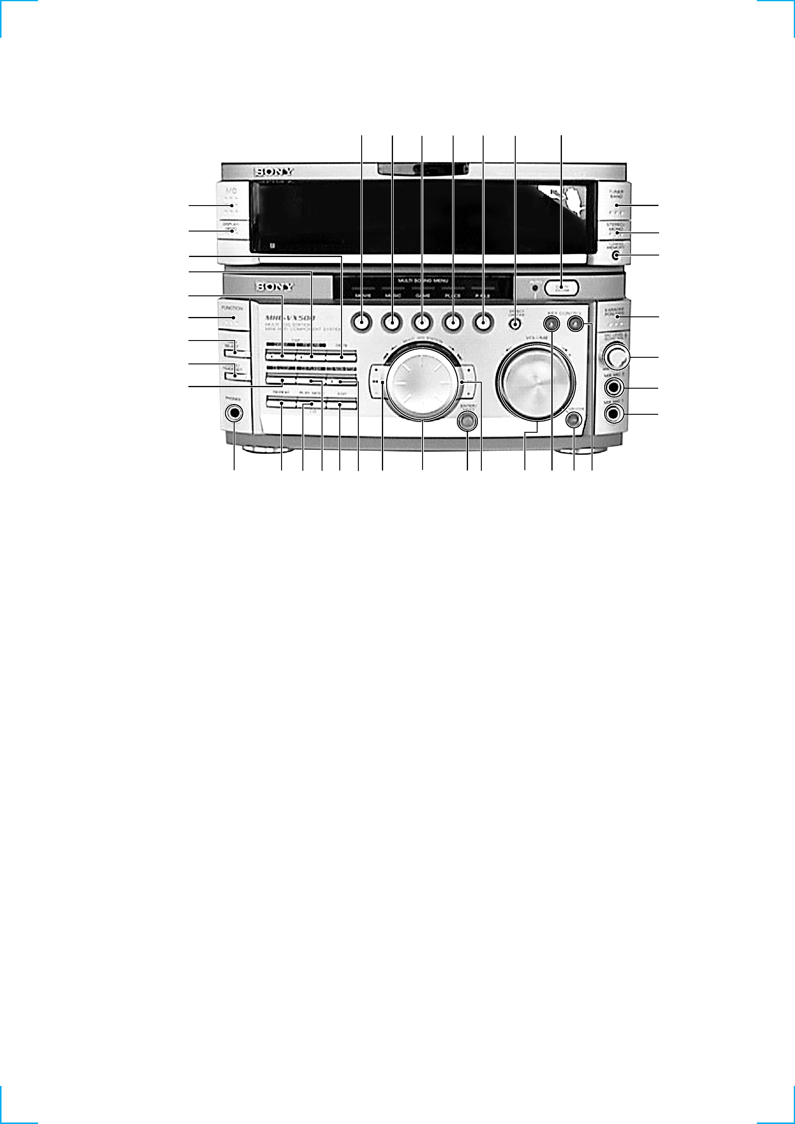
Front Panel
SECTION 1
GENERAL
1 MOVIE button
2 MUSIC button
3 GAME button
4 PLACE button
5 P FILE button
6 EFFECT ON/OFF button
7 OPEN/CLOSE button
8 TUNER BAND button
9 STEREO/MONO button
0 MEMORY button
qa KARAOKE PON/MIX button
qs MIC LEVEL/ECHO VOL dial
qd MIX MIC1 jack
qf GROOVE button
qg VOLUME dial
qh M + button
qj ENTER/NEXT button
qk MULTI JOG STATION dial
ql m button
w; NON-STOP button
wa EDIT button
ws FLASH button
wd PLAY MODE button
wf REPEAT button
wg PHONES jack
wh LOOP button
wj CLOCK/TIMER SET button
wk TIMER SELECT button
wl FUNCTION button
e; PROLOGIC button
ea DSP button
es DBFB button
ed DISPLAY/DEMO button
ef I/1 (POWER) button
eg MIX MIC2 jack
eh KEY CONTROL (#)
ej KEY CONTROL (2)
1
2
3
4
5
6
7
8
9
0
qa
qs
qd
qf
eg
qg
qjqh
wg
wh
wj
wk
wl
ed
ef
e;
ej
eh
qk
ql
wa
wd
wf
w;
ea
es
ws
4
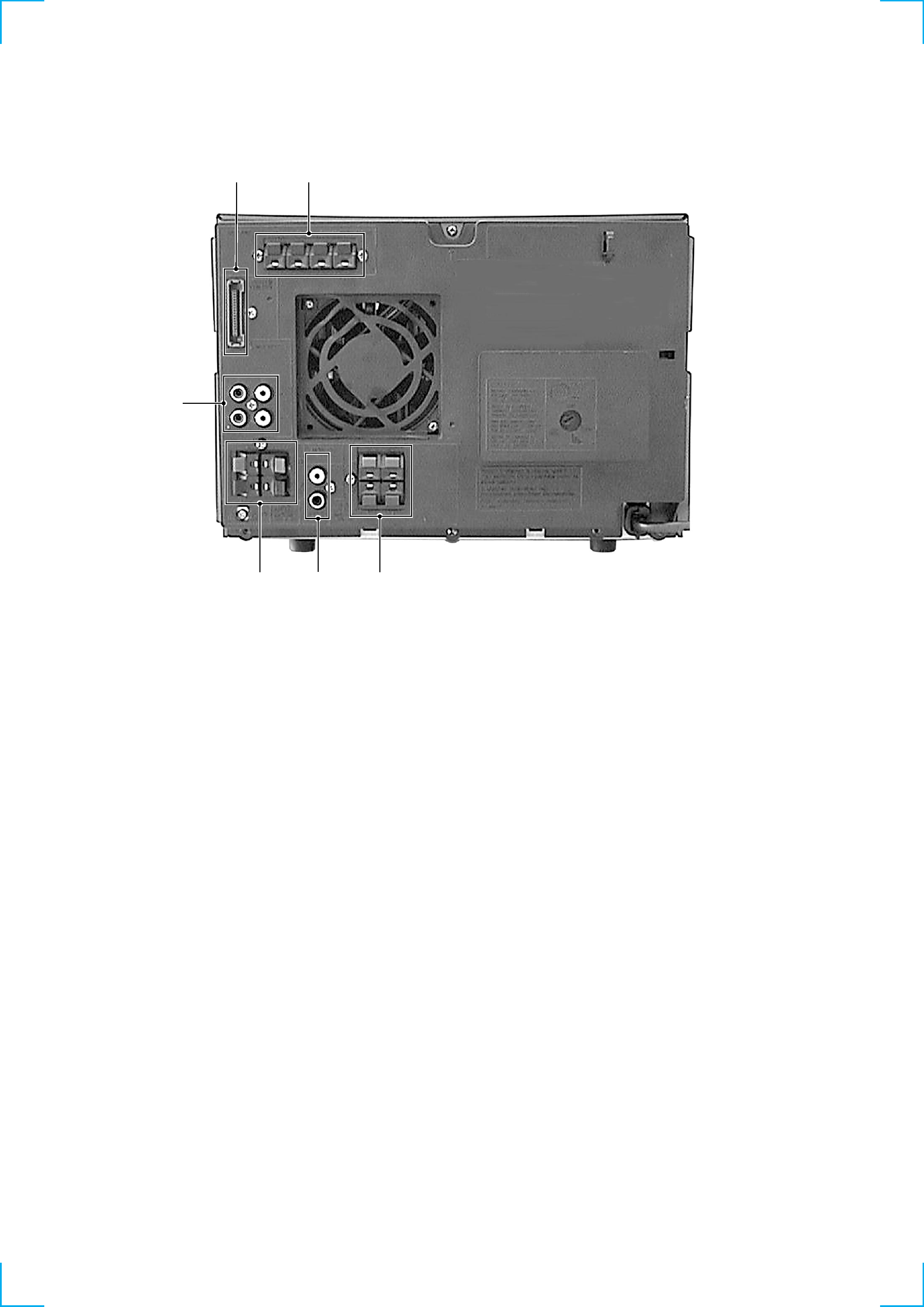
Rear Panel
1 SYSTEM CONTROL jack
2 ANTENNA terminal
3 REAR SPEAKER terminal
4 MONITOR OUT jack
5 FRONT SPEAKER terminal
6 MD/VIDEO 1 jack
2
3
4
1
5
6
5
SECTION 2
DISASSEMBLY
Note: Follow the disassembly procedure in the numerical order given.
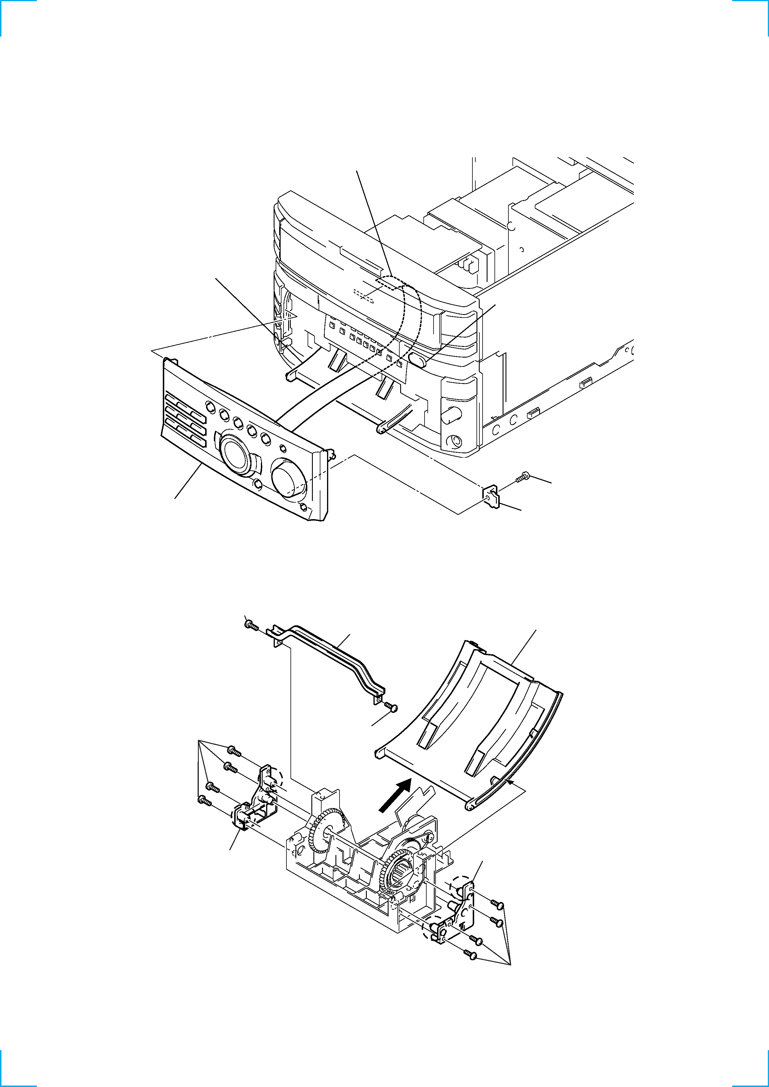
2-1. SLIDING PANEL ASSEMBLY
2-2. LEVEL SLIDER
(Perform this DISASSEMBLY after the front panel is removed.)
NOTE FOR INSTALLATION:
Attach in the reverse order, but make sure the rollers (a, b) of the
holder (L) assembly and holder (R) assembly fit into the grooves of
the level slider.
4
Flat type cable (19 core)
2
Screw (BVTP 3
× 8)
3
Holder level
5
Sliding panel assembly
Slide mechanism
1
Push the OPEN/CLOSE button to
open the Sliding panel assembly.
1
Screw (BVTP2.6
× 8)
4
Four screws
(BVTP2.6
× 8)
5
Holder (L) assembly
a
a
b
b
6
Four screws (BVTP2.6
× 8)
7
Holder (R) assembly
8
Remove the Level slider direction of arrow.
2
Screw
(BVTP2.6
× 8)
3
Top bracket