SERVICE MANUAL
Sony Corporation
Audio Group
Published by Sony Engineering Corporation
US Model
Canadian Model
AEP Model
UK Model
E Model
Australian Model
FM STEREO FM-AM RECEIVER
9-879-447-02
2005I16-1
© 2005.09
Ver. 1.1 2005.09
SPECIFICATIONS
STR-K670P
· STR-K670P is the tuner and the amplifier
section in HT-DDW670 and HTP-82DWK.
Models of area code AUS
(6 ohms 120 Hz 20 kHz, THD 0.09%)
FRONT2):
40 W/ch
CENTER2):
40 W
SURR2):
40 W/ch
(6 ohms 100 Hz, THD 0.09%)
(6 ohms 1 kHz, THD 0.7%)
(6 ohms 100 Hz, THD 0.7%)
(6 ohms 1 kHz, THD 10%)
FRONT2):
50 W/ch
CENTER2):
50 W
SURR2):
50 W/ch
FRONT2):
85 W/ch
CENTER2):
85 W
SURR2):
85 W/ch
AUDIO POWER SPECIFICATIONS
POWER OUTPUT AND TOTAL HARMONIC
DISTORTION:
(Models of area code US only)
With 6 ohm loads, both channels driven, from
120 20,000 Hz; rated 60 watts per channel
minimum RMS power, with no more than 0.7%
total harmonic distortion from 250 milliwatts to
rated output.
Amplifier section
Power Output1)
Models of area code US
Models of area code CND
(6 ohms 1 kHz, THD 10%)
(6 ohms 100 Hz, THD 10%)
FRONT2):
100 W/ch
CENTER2):
100 W
SURR2):
100 W/ch
SUB WOOFER 2):
100 W
(6 ohms 1 kHz, THD 0.7%)
FRONT2):
60 W/ch
CENTER2):
60 W
SURR2):
60 W/ch
FRONT2):
100 W/ch
CENTER2):
100 W
SURR2):
100 W/ch
(6 ohms 100 Hz, THD 0.7%)
(6 ohms 1 kHz, THD 10%)
SUB WOOFER2):
100 W
(6 ohms 100 Hz, THD 10%)
SUB WOOFER2):
85 W
SUB WOOFER2):
40 W
(6 ohms 100 Hz, THD 10%)
SUB WOOFER2):
85 W
SUB WOOFER2):
50 W/ch
(6 ohms 100 Hz, THD 10%)
SUB WOOFER2):
50 W
(6 ohms 100 Hz, THD 0.7%)
SUB WOOFER2):
60 W
Models of area code AEP, UK, MX, SP, E51
(6 ohms 1 kHz, THD 0.7%)
FRONT2):
50 W/ch
CENTER2):
50 W
SURR2):
50 W/ch
(6 ohms 1 kHz, THD 10%)
FRONT2):
85 W/ch
CENTER2):
85 W
SURR2):
85 W/ch
Continued on next page
Manufactured under license from Dolby Laboratories.
"Dolby", "Pro Logic" and the double-D symbol are trademarks of Dolby Laboratories.
"DTS" and "DTS Digital Surround" are registered trademarks of Digital Theater
Systems, Inc.
2
STR-K670P
FM tuner section
Tuning range
87.5 - 108.0 MHz
Antenna
FM wire antenna
Antenna terminals
75 ohms, unbalanced
Intermediate frequency
10.7 MHz
AM tuner section
Tuning range
Models of area code US, CND
With 10-kHz tuning scale: 530 - 1,710 kHz3)
With 9-kHz tuning scale:
531 - 1,710 kHz3)
Models of area code AEP, UK, AUS, SP
With 9-kHz tuning scale:
531 1,602 kHz
Models of area code E51
With 10-kHz tuning scale: 530 - 1,610 kHz3)
With 9-kHz tuning scale:
531 - 1,602 kHz3)
Models of area code MX
With 10-kHz tuning scale: 530 - 1,610 kHz
Antenna
Loop antenna
Intermediate frequency
450 kHz
3) You can change the AM tuning scale to 9 kHz or
10 kHz. After tuning in any AM station, turn off the
receiver. While holding down PRESET TUNING +
or TUNING +, press ?/1. All preset stations will be
erased when you change the tuning scale. To reset
the scale to 10 kHz (or 9 kHz), repeat the procedure.
1) Measured under the following conditions:
2) Depending on the sound field settings and the
source, there may be no sound output.
Inputs (Analog)
Inputs (Digital)
Output (Analog)
Reproduction frequency range:
28 20,000 Hz
Tone
Area code
Power requirements
US, CND
120 V AC, 60 Hz
AEP, UK, SP
230 V AC, 50 Hz
AUS, E51
240 V AC, 50 Hz
MX
127 V AC, 60 Hz
SA-CD/CD, DVD
VIDEO 1, 2
Sensitivity: 800 mV
Impedance: 50 k ohms
DVD (Coaxial)
Sensitivity:
Impedance: 75 ohms
SA-CD/CD (Optical)
Sensitivity:
Impedance:
SUB WOOFER
Voltage: 2 V
Impedance: 1 k ohm
Gain levels
±6 dB, 1 dB step
General
Power requirements
Area code
Power requirements
US, CND
120 V AC, 60 Hz
2
AEP, UK
30 V AC, 50/60 Hz
AUS
240 V AC, 50 Hz
SP
220 230 V AC, 50/60 Hz
E15
120/220/240 V AC,
50/60 Hz
Power consumption
Power consumption (during standby mode)
0.2 W
Dimensions (w/h/d) (Approx.)
430
× 145 × 301.5 mm
(17
× 5 6/8 × 11 7/8 inches)
including projecting parts
and controls
Mass (Approx.)
6.5 kg (14 lb 6 oz)
Area code
Power consumption
US, AEP, UK, E51,
SP, MX, AUS
160 W
CND
220 VA
Design and specifications are subject to change
without notice
MX
127 V AC, 60 Hz
·Abbreviation
AUS: Australian model
CND
: Canadian model
E51
: Chilean and Peruvian models
MX
: Mexican model
SP
: Singapore model
3
STR-K670P
SAFETY CHECK-OUT
After correcting the original service problem, perform the following
safety check before releasing the set to the customer:
Check the antenna terminals, metal trim, "metallized" knobs, screws,
and all other exposed metal parts for AC leakage.
Check leakage as described below.
LEAKAGE TEST
The AC leakage from any exposed metal part to earth ground and
from all exposed metal parts to any exposed metal part having a
return to chassis, must not exceed 0.5 mA (500 microamperes.).
Leakage current can be measured by any one of three methods.
1. A commercial leakage tester, such as the Simpson 229 or RCA
WT-540A. Follow the manufacturers' instructions to use these
instruments.
2. A battery-operated AC milliammeter. The Data Precision 245
digital multimeter is suitable for this job.
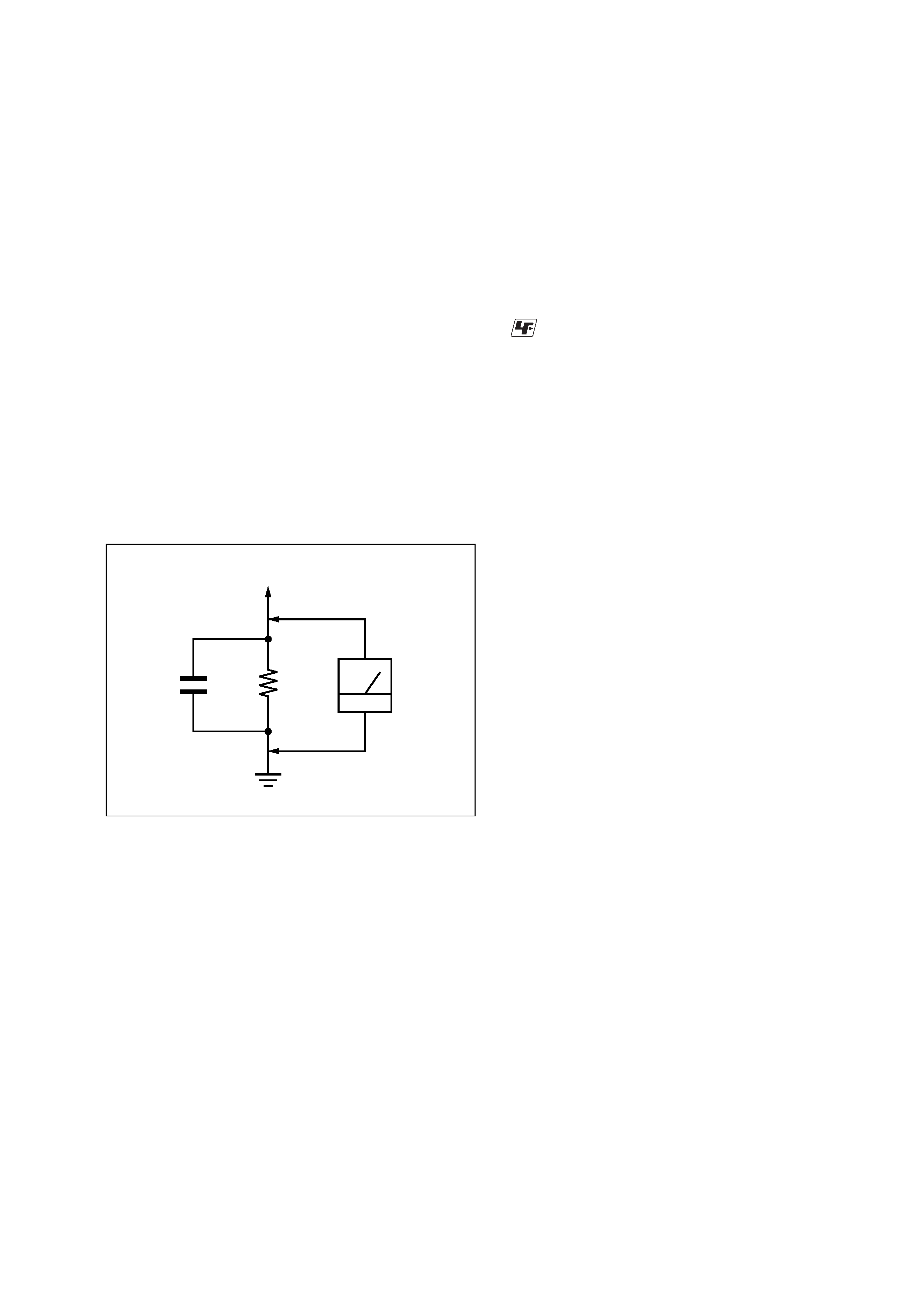
3. Measuring the voltage drop across a resistor by means of a
VOM or battery-operated AC voltmeter. The "limit" indication
is 0.75 V, so analog meters must have an accurate low-voltage
scale. The Simpson 250 and Sanwa SH-63Trd are examples
of a passive VOM that is suitable. Nearly all battery operated
digital multimeters that have a 2 V AC range are suitable. (See
Fig. A)
Fig. A.
Using an AC voltmeter to check AC leakage.
1.5 k
0.15
µF
AC
voltmeter
(0.75 V)
To Exposed Metal
Parts on Set
Earth Ground
Notes on chip component replacement
· Never reuse a disconnected chip component.
· Notice that the minus side of a tantalum capacitor may be
damaged by heat.
UNLEADED SOLDER
Boards requiring use of unleaded solder are printed with the lead-
free mark (LF) indicating the solder contains no lead.
(Caution: Some printed circuit boards may not come printed with
the lead free mark due to their particular size)
: LEAD FREE MARK
Unleaded solder has the following characteristics.
· Unleaded solder melts at a temperature about 40 °C higher
than ordinary solder.
Ordinary soldering irons can be used but the iron tip has to be
applied to the solder joint for a slightly longer time.
Soldering irons using a temperature regulator should be set to
about 350
°C.
Caution: The printed pattern (copper foil) may peel away if
the heated tip is applied for too long, so be careful!
· Strong viscosity
Unleaded solder is more viscou-s (sticky, less prone to flow)
than ordinary solder so use caution not to let solder bridges
occur such as on IC pins, etc.
· Usable with ordinary solder
It is best to use only unleaded solder but unleaded solder may
also be added to ordinary solder.
SAFETY-RELATED COMPONENT WARNING!!
COMPONENTS IDENTIFIED BY MARK 0 OR DOTTED LINE
WITH MARK 0 ON THE SCHEMATIC DIAGRAMS AND IN
THE PARTS LIST ARE CRITICAL TO SAFE OPERATION.
REPLACE THESE COMPONENTS WITH SONY PARTS WHOSE
PART NUMBERS APPEAR AS SHOWN IN THIS MANUAL OR
IN SUPPLEMENTS PUBLISHED BY SONY.
ATTENTION AU COMPOSANT AYANT RAPPORT
À LA SÉCURITÉ!
LES COMPOSANTS IDENTIFIÉS PAR UNE MARQUE 0 SUR
LES DIAGRAMMES SCHÉMATIQUES ET LA LISTE DES
PIÈCES
SONT
CRITIQUES
POUR
LA
SÉCURITÉ
DE
FONCTIONNEMENT. NE REMPLACER CES COM- POSANTS
QUE PAR DES PIÈCES SONY DONT LES NUMÉROS SONT
DONNÉS DANS CE MANUEL OU DANS LES SUPPLÉMENTS
PUBLIÉS PAR SONY.
4
STR-K670P
TABLE OF CONTENTS
1.
GENERAL ................................................................... 5
2.
TEST MODE ............................................................... 10
3.
DIAGRAMS
3-1.
Block Diagram -- MAIN Section -- .............................. 12
3-2.
Block Diagram -- DISPLAY/POWER Section -- ........ 13
3-3.
Printed Wiring Board
-- DIGITAL Board (Side A) -- ...................................... 14
3-4.
Printed Wiring Board
-- DIGITAL Board (Side B) -- ...................................... 15
3-5.
Schematic Diagram -- DIGITAL Board (1/4) -- .......... 16
3-6.
Schematic Diagram -- DIGITAL Board (2/4) -- .......... 17
3-7.
Schematic Diagram -- DIGITAL Board (3/4) -- .......... 18
3-8.
Schematic Diagram -- DIGITAL Board (4/4) -- .......... 19
3-9.
Printed Wiring Board -- MAIN Section -- ................... 20
3-10. Schematic Diagram -- MAIN Section (1/3) -- ............. 21
3-11. Schematic Diagram -- MAIN Section (2/3) -- ............. 22
3-12. Schematic Diagram -- MAIN Section (3/3) -- ............. 23
3-13. Printed Wiring Board -- STANDBY Section -- ........... 24
3-14. Printed Wiring Board -- DISPLAY Section -- ............. 25
3-15. Schematic Diagram -- DISPLAY Section -- ................ 26
4.
EXPLODED VIEWS
4-1.
Front Panel Section ......................................................... 34
4-2.
Chassis Section-1 ............................................................ 35
4-3.
Chassis Section-2 ............................................................ 36
5.
ELECTRICAL PARTS LIST .................................. 37
Parts No.
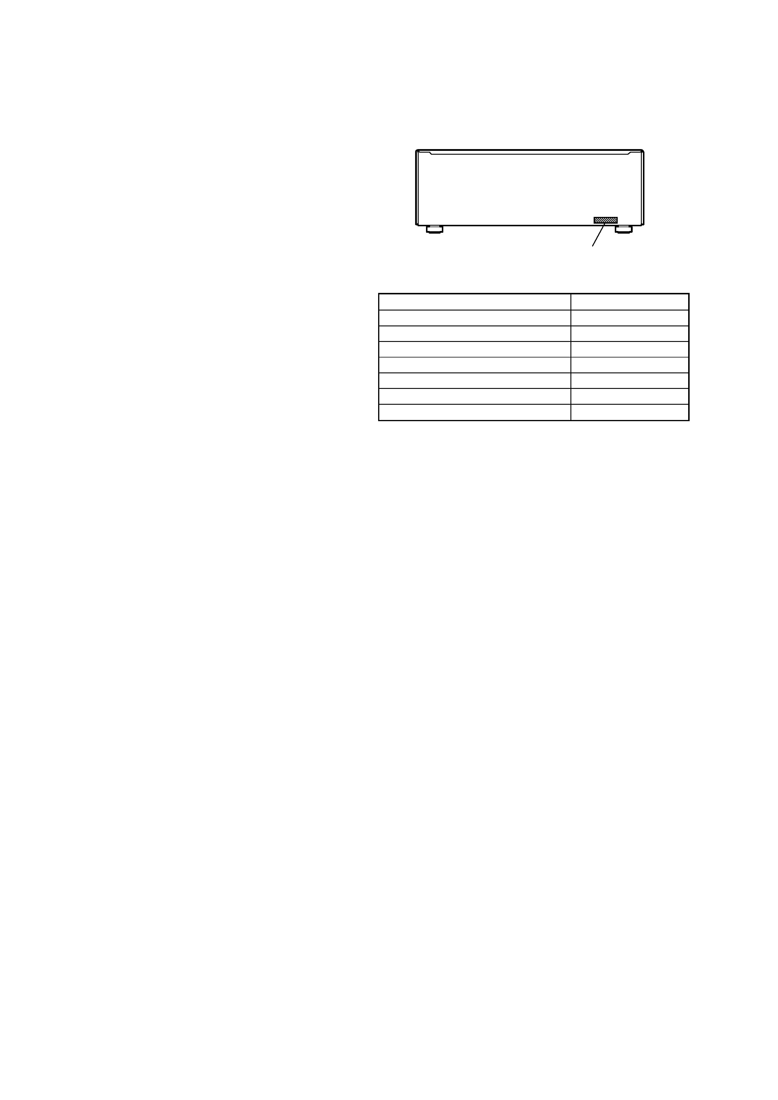
MODEL IDENTIFICATION
BACK PANEL
·Abbreviation
AUS: Australian model
CND
: Canadian model
E51
: Chilean and Peruvian models
MX
: Mexican model
SP
: Singapore model
Model
Part No.
US model
2-342-334-0[]
CND model
2-342-334-1[]
AUS model
2-342-334-2[]
SP model
2-342-334-3[]
MX model
2-342-334-4[]
E51 model
2-342-334-5[]
AEP and UK models
2-342-334-8[]
5
STR-K670P
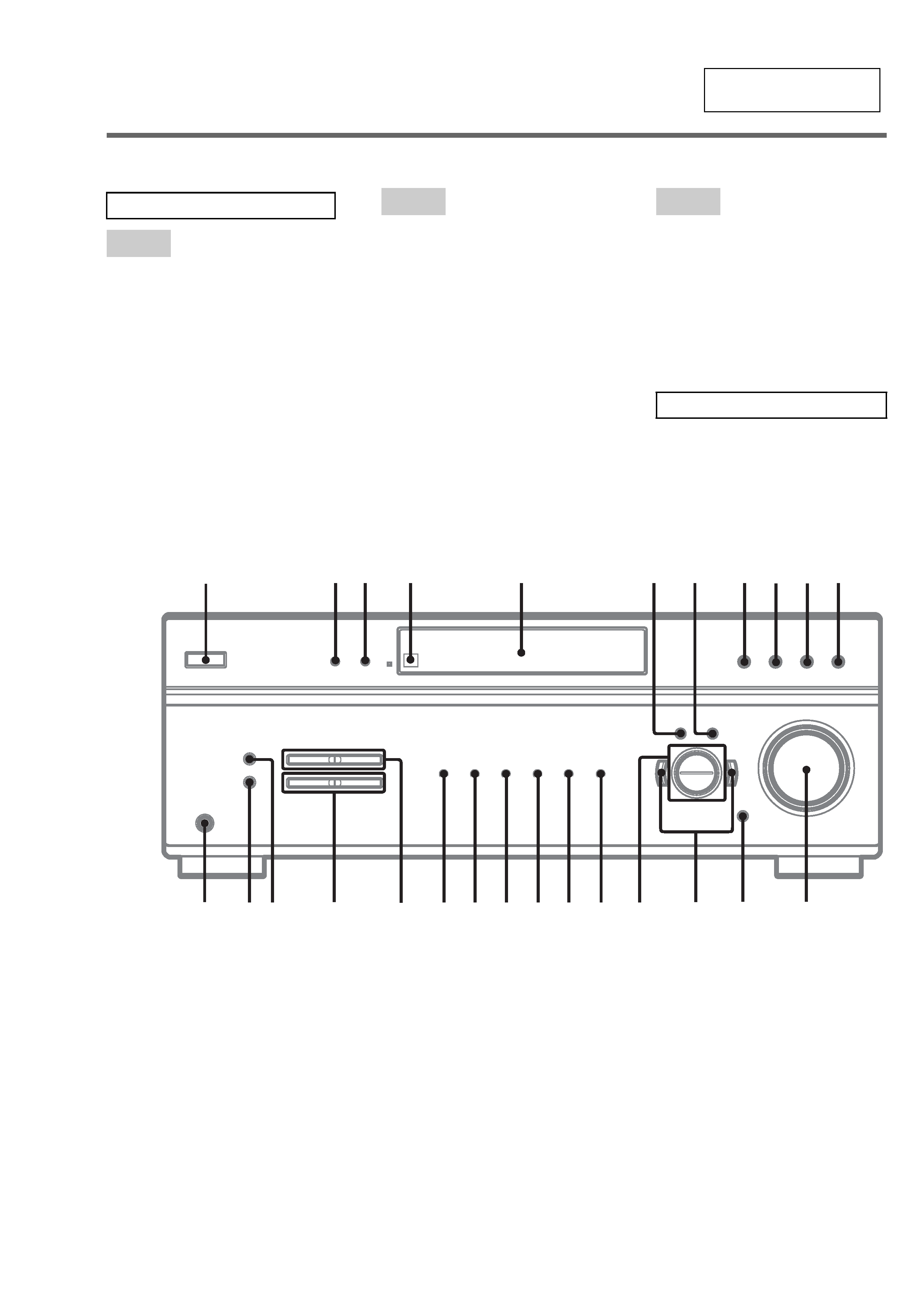
SECTION 1
GENERAL
This section is extracted
from instruction manual.
Main unit
$)' 9
$0 qh
',00(5 3
',63/$< 2
'LVSOD\ 5
'9' ql
(17(5 7
)0 qj
)0 02'( wg
,1387 02'( qd
,5 UHFHSWRU
4
0$,1 0(18 6
0$67(5 92/80( ± qs
0(025< wf
029,( 0
086,& qa
3+21(6 MDFN
wh
35(6(7 781,1* ± ws
6$&'&' qk
781,1*± wd
9,'(2 wa
9,'(2 w;
&+ 8
?/1 SRZHU
1
! qf
± qg
$/3+$%(7,&$/25'(5
$ +
,2
3 =
180%(56 $1'6<0%2/6
6
4
23
1
qh
qj
qk
ql
w;
wa
qd
qf
qs
5
7
89
qa
q;
qg
ws
wd
wh
wgwf