
STR-DE695 4-247-631-12 (1) US
FM Stereo
FM-AM Receiver
4-247-631-12(1)
STR-DE695
Owner's Record
The model and serial numbers are located at the rear of the unit. Record the serial
number in the space provided below. Refer to them whenever you call upon your Sony
dealer regarding this product.
Model No.
Serial No.
© 2003 Sony Corporation
Operating Instructions
01US01COVSEI.p65
3/21/03, 9:03 AM
1
2US
STR-DE695 4-247-631-12 (1) US
WARNING
To prevent fire or shock hazard, do not
expose the unit to rain or moisture.
To prevent fire, do not cover the ventilation of the
apparatus with newspapers, table-cloths, curtains,
etc. And don't place lighted candles on the apparatus.
To prevent fire or shock hazard, do not place objects
filled with liquids, such as vases, on the apparatus.
Don't throw away the battery with
general house waste, dispose of it
correctly as chemical waste.
Do not install the appliance in a confined space, such
as a bookcase or built-in cabinet.
For customers in the United States
This symbol is intended to alert the
user to the presence of uninsulated
"dangerous voltage" within the
product's enclosure that may be of
sufficient magnitude to constitute a
risk of electric shock to persons.
This symbol is intended to alert the
user to the presence of important
operating and maintenance (servicing)
instructions in the literature
accompanying the appliance.
WARNING
This equipment has been tested and found to comply
with the limits for a Class B digital device, pursuant
to Part 15 of the FCC Rules. These limits are
designed to provide reasonable protection against
harmful interference in a residential installation. This
equipment generates, uses, and can radiate radio
frequency energy and, if not installed and used in
accordance with the instructions, may cause harmful
interference to radio communications. However, there
is no guarantee that interference will not occur in a
particular installation. If this equipment does cause
harmful interference to radio or television reception,
which can be determined by turning the equipment
off and on, the user is encouraged to try to correct the
interference by one or more of the following
measures:
Reorient or relocate the receiving antenna.
Increase the separation between the equipment and
receiver.
Connect the equipment into an outlet on a circuit
different from that to which the receiver is
connected.
Consult the dealer or an experienced radio/TV
technician for help.
CAUTION
You are cautioned that any changes or modification
not expressly approved in this manual could void
your authority to operate this equipment.
Note to CATV system installer:
This reminder is provided to call CATV system
installer's attention to Article 820-40 of the NEC that
provides guidelines for proper grounding and, in
particular, specifies that the cable ground shall be
connected to the grounding system of the building, as
close to the point of cable entry as practical.
For customers in Canada
CAUTION
TO PREVENT ELECTRIC SHOCK, MATCH WIDE
BLADE OF PLUG TO WIDE SLOT, FULLY
INSERT.
CAUTION
TO PREVENT ELECTRIC SHOCK, DO NOT USE
THIS POLARIZED AC PLUG WITH AN
EXTENSION CORD, RECEPTACLE OR OTHER
OUTLET UNLESS THE BLADES CAN BE FULLY
INSERTED TO PREVENT BLADE EXPOSURE.
ENERGY STAR® is a U.S. registered
mark.
As an
ENERGY STAR® partner, Sony
Corporation has determined that this
product meets the
ENERGY STAR®
guidelines for energy efficiency.
This receiver incorporates Dolby* Digital and Pro
Logic Surround and the DTS** Digital Surround
System.
* Manufactured under license from Dolby
Laboratories.
"Dolby", "Pro Logic" and the double-D symbol
are trademarks of Dolby Laboratories.
** "DTS", "DTS-ES Extended Surround" and
"Neo: 6" are trademarks of Digital Theater
Systems, Inc.
01US02TOCSEI.p65
3/21/03, 9:03 AM
2

3US
STR-DE695 4-247-631-11 (1) US
Table of Contents
List of Button Locations and
Reference Pages
Main unit ............................................... 5
Hooking Up the Components
Required cords ....................................... 6
Antenna hookups ................................... 7
Audio component hookups .................... 8
Video component hookups .................... 9
Digital component hookups ................. 10
Multi channel input hookups ............... 12
Other hookups ..................................... 13
Hooking Up and Setting Up
the Speaker System
Speaker system hookups ..................... 15
Performing initial setup operations ..... 17
Multi channel surround setup .............. 17
Checking the connections .................... 22
Basic Operations
Selecting the component ..................... 23
Changing the display ........................... 24
Enjoying Surround Sound
Using only the front speakers
(2 Channel Stereo) ........................ 25
Enjoying higher fidelity sound ............ 25
Selecting a sound field ........................ 26
Selecting the surround back decoding
mode (SURR BACK
DECODING) ................................ 28
Understanding the multi channel
surround displays .......................... 30
Customizing sound fields .................... 31
Receiving Broadcasts
Direct tuning ........................................ 34
Automatic tuning ................................. 35
Preset tuning ........................................ 35
Other Operations
Naming preset stations and program
sources ........................................... 37
Recording ............................................ 37
Using the Sleep Timer ......................... 38
Adjustments using the CUSTOM
menu .............................................. 39
Changing the command mode of the
receiver .......................................... 39
CONTROL A1II control system ......... 40
Operations Using the Remote
RM-PP412
Before you use your remote ................ 42
Remote button description ................... 42
Selecting the command mode of the
remote ............................................ 46
Programming the remote ..................... 46
Additional Information
Precautions .......................................... 50
Troubleshooting ................................... 50
Specifications ...................................... 53
Tables of settings using the MAIN
MENU button ................................ 56
Adjustable parameters for each sound
field ............................................... 57
4US
STR-DE695 4-247-631-11 (1) US
R
R
L
L
L
L
R
BACK
FRONT B
FRONT A
SURROUND
AC OUTLET
IMPEDANCE USE 8-16
KERS
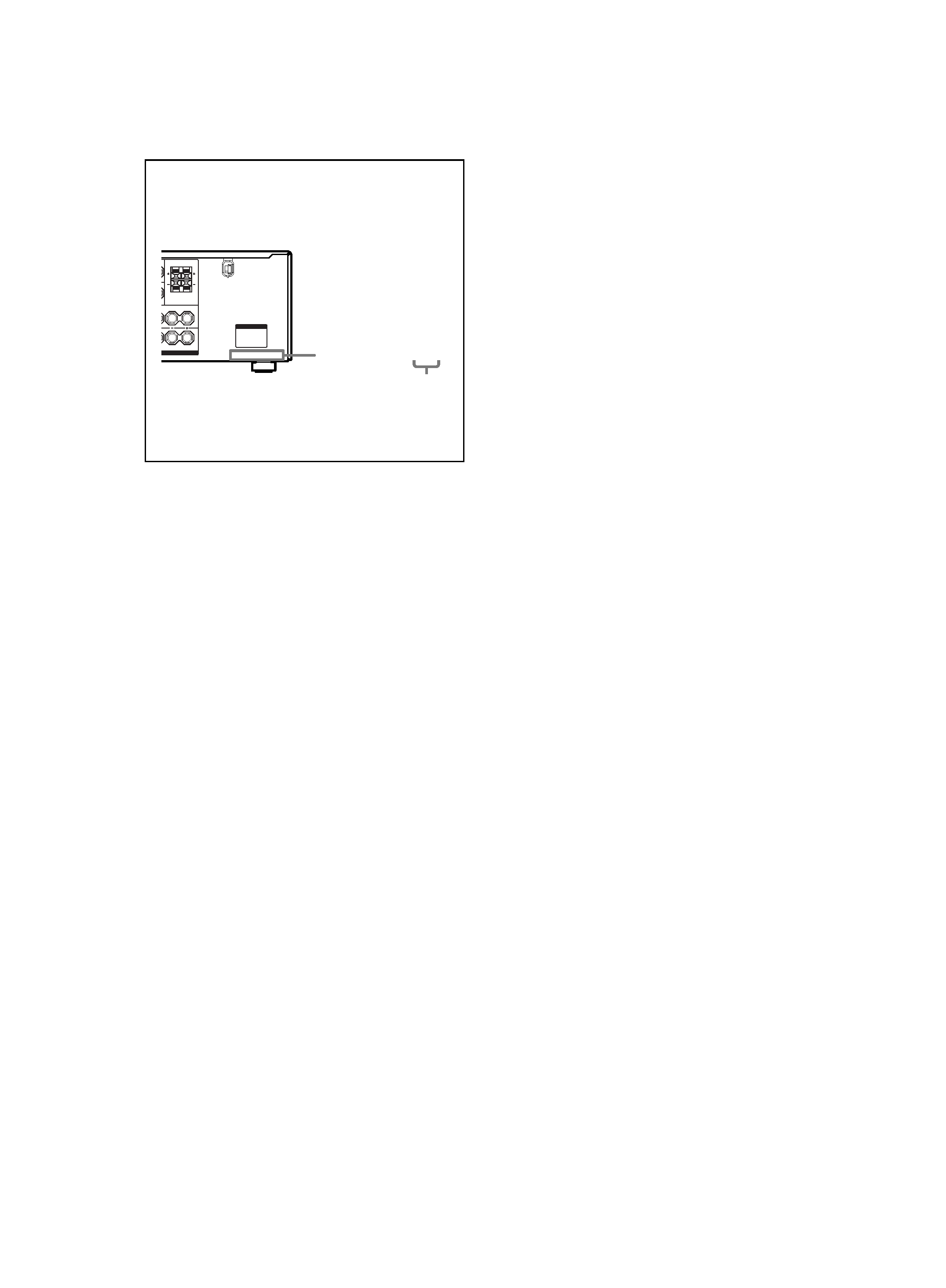
4-XXX-XXX-XX AA
Area code
About This Manual
About area codes
The area code of the receiver you purchased is
shown on the lower portion of the rear panel (see
the illustration below).
Any differences in operation, according to the
area code, are clearly indicated in the text, for
example, "Models of area code AA only".
Tip
The instructions in this manual describe the controls
on the receiver. You can also use the controls on the
supplied remote if they have the same or similar
names as those on the receiver. For details on the use
of your remote, see pages 4249.
Note for the supplied remote
RM-PP412
The TV/SAT, PHONO, SOURCE, DIRECT,
AAC BI-LING, 12 and ON SCREEN buttons
on the remote are not available.
5US
List
of
Button
Locations
and
Reference
Pages
STR-DE695 4-247-631-11 (1) US
?/1
g
qj
qk
ql
w;
wa
ws
wd
wj
wk
wl
e;
ea
es
ed
ef
wh
wf
wg
12 35
9 0
6qa qsqd qf
qg
qh
7
4
8
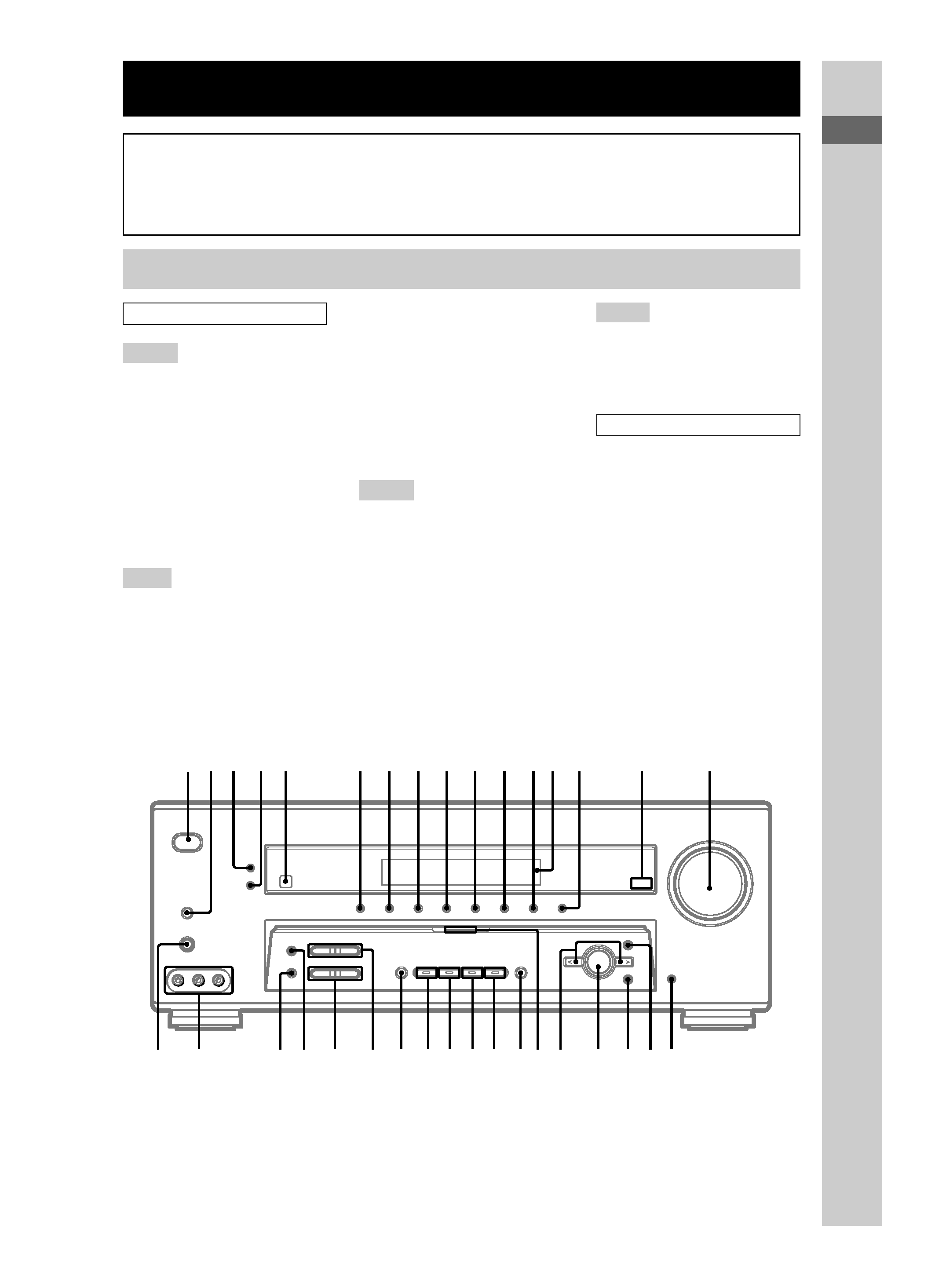
List of Button Locations and Reference Pages
Main unit
MD/TAPE q; (23)
MEMORY ea (35)
MOVIE (button/indicator) wg (26,
51)
MULTI CHANNEL DECODING
(indicator) ws (23)
MULTI CH IN wd (23)
MUSIC (button/indicator) wf (26,
27, 51)
P U
PHONES (jack) ef (24, 30, 51)
PRESET TUNING +/ wl
(35, 36, 54)
SPEAKERS (OFF/A/B/A+B) 2
(15, 24, 50)
SURR BACK DECODING wk
(28, 39)
SURR BACK DECODING
(indicator) qg (28)
TUNER FM/AM qs (23, 35, 36,
37)
TUNING +/ e; (35)
V Z
VIDEO 1 6 (23)
VIDEO 2 7 (23)
VIDEO 3 8 (23)
VIDEO 3 INPUT (jacks) ed (9)
NUMBERS AND SYMBOLS
2CH (button/indicator) wj (25,
27, 33)
?/1 (power) 1 (17, 22, 33, 39
54)
</> wa (18, 32, 33, 37, 39, 56)
ALPHABETICAL ORDER
A H
A.F.D. (button/indicator) wh (25
27)
AUX qf (23)
CD/SACD qa (23)
DIMMER 4 (24)
DISPLAY 3 (24, 52)
Display qd (24)
DVD 9 (23)
ENTER ql (17, 37, 39)
FM MODE es (34)
I O
INPUT MODE qj (23)
IR (receptor) 5 (42, 52)
Jog dial w; (18, 32, 33, 37, 39,
56)
MAIN MENU qk (18, 32, 33, 37,
39, 56)
MASTER VOLUME qh (22, 24,
50)
How to use this page
Use this page to find the location of buttons that are
mentioned in the text.
Illustration number
r
DISPLAY 3 (24, 52)
RR
Name of button/part
Reference page