MICROFILM
SERVICE MANUAL
FM STEREO/FM-AM-RECEIVER
US Model
AEP Model
UK Model
STR-DE135
SPECIFICATIONS
Photo: US model
Audio power specifications (US model)
POWER OUTPUT AND TOTAL HARMONIC DISTORTION
With 8-ohm load, both channels driven, from 20 20,000 Hz,
rated 100 watts per channel minimum RMS power, with no
more than 0.09 % total harmonic distortion from 250 milli-
watts to rated output.
Amplifier section
Stereo mode
(8 ohms at 20 Hz 20 kHz less than
0.09 % total harmonic distortion)
100 W + 100 W (US model)
(DIN 1 kHz, 4 ohms)
60 W + 60 W (AEP, UK models)
Frequency response
TV/SAT, CD, MD/TAPE, VIDEO
(US model)
TV/LD, CD, MD/TAPE, VIDEO
(AEP, UK models)
10 Hz 50 Hz ± 1 dB
Inputs
Sensitivity
Impedance
S/N
CD,
MD/TAPE,
150 mV
50
78 dB
TV/SAT,
kilohms
VIDEO
(US model)
Sensitivity
Impedance
S/N
CD,
MD/TAPE,
150 mV
50
78 dB
TV/LD,
kilohms
VIDEO
(AEP, UK models)
outputs
MD/TAPE REC OUT:
Voltage: 150 mV,
impedance: 10 kilohms
VIDEO AUDIO OUT:
Voltage: 150 mV,
impedance: 10 kilohms
PHONES: Accepts low and high
impedance headphones
Muting
Full mute
BASS BOOST
+ 10 dB at 70 Hz
TONE
± 8 dB at 100 Hz and 10 kHz
Tuner Section
FM stereo, FM/AM superheterodyne tuner
FM tuner section
Tuning range
87.5 108.0 MHz
Antenna terminals
75 ohms, unbalanced
Intermediate frequency
10.7 MHz
Sensitivity
Mono: 18.3 dBf, 4.5
µV
Stereo: 38.3 dBf, 45
µV (US model)
Mono: 18.3 dBf, 2.2
µV/75 ohms
Stereo: 38.3 dBf, 22.5
µV/75 ohms
(AEP, UK models)
Usable sensitivity
11.2 dBf, 2
µV (IHF) (US model)
11.2 dBf, 1
µV/75 ohms (IHF)
(AEP, UK models)
S/N
Mono: 76 dB
Stereo: 70 dB
Harmonic distortion at 1 kHz
Mono: 0.3 %
Stereo: 0.5 %
Separation
45 dB at 1kHz
Frequency response
30 Hz 15 kHz
dB
Selectivity
60 dB at 400 kHz
AM tuner section
Tuning range
10 kHz interval*
530 1710 kHz
9 kHz interval
531 1710 kHz (US model)
531 1602 kHz (AEP, UK models)
+0.5
2
Continued on next page

2
TABLE OF CONTENTS
1.
SERVICING NOTES ............................................... 3
2.
GENERAL ................................................................... 4
3.
DISASSEMBLY ......................................................... 5
4.
TEST MODE ............................................................... 7
5.
DIAGRAMS
5-1. Note for Printed Wiring Boards and
Schematic Diagrams .......................................................
9
5-2. Printed Wiring Board MAIN Board ........................ 11
5-3. Schematic Diagram MAIN Board (1/2) .................. 13
5-4. Printed Wiring Boards
DISPLAY Board/KEY Board/VOLUME Board/
TONE Board/POWER SWITCH Board ................... 15
5-5. Schematic Diagram
PANEL Section ......................................................... 19
5-6. Printed Wiring Boards
PANEL Section ......................................................... 23
5-7. Schematic Diagram
MAIN Board (2/2)/SPK SWITCH Board/
SECONDARY Board/PRIMARY Board/
STANDBY TRANS Board ....................................... 25
5-8. IC Pin Function Description ........................................... 26
6.
EXPLODED VIEWS ................................................ 28
7.
ELECTRICAL PARTS LIST ............................... 31
SAFETY-RELATED COMPONENT WARNING!!
COMPONENTS IDENTIFIED BY MARK
! OR DOTTED
LINE WITH MARK
! ON THE SCHEMATIC DIAGRAMS
AND IN THE PARTS LIST ARE CRITICAL TO SAFE
OPERATION. REPLACE THESE COMPONENTS WITH
SONY PARTS WHOSE PART NUMBERS APPEAR AS
SHOWN IN THIS MANUAL OR IN SUPPLEMENTS PUB-
LISHED BY SONY.
Antenna
Loop antenna
Intermediate frequency
450 kHz
Usable sensitivity
50 dB/m (at 1,000 kHz)
S/N
54 dB (at 50 mV/m)
Harmonic distortion
0.5 % (50 mV/m, 400Hz)
Selectivity
At 10 kHz: 40 dB
At 9 kHz: 35 dB (US model)
35 dB (AEP, UK models)
* You can change the AM tuning interval between 9 kHz and 10kHz.
After tuning in any AM station, turn off the receiver. Hold down the
PRESET TUNING + button and press the
1/u (power) button. All pre-
set stations will be erased when you change the interval. To reset the
interval, repeat the procedure.
(US model)
General
System
Tuner section:
PLL quartz-locked digital
synthesizer system
Preamplifier section:
Low-noise NF type equalizer
Power amplifier section:
Pure-complementary SEPP
Power requirements
120 V AC, 60 Hz (US model)
230 V AC, 50/60 Hz
(AEP, UK models)
Power consumption
155 W (US model)
135 W (AEP, UK models)
AC outlets
1 switched, total 120 W/1A Max
(US, UK models)
switch 100 W max (AEP model)
Dimensions
430
× 144 × 306 mm
(17
× 56/8 × 124/8 inches)
Mass (Approx.)
8.1 kg (17 lb 13 oz) (US model)
6.7 kg (AEP, UK models)
Supplied accessories
FM wire antenna (1)
AM loop antenna (1)
Remote commander (remote) (1)
Size AA (R6) batteries (2)
Specifications indicated are measured at 230 V AC, 50Hz.
(AEP, UK models)
Design and specifications are subject to change without notice.
3
SECTION 1
SERVICING NOTES
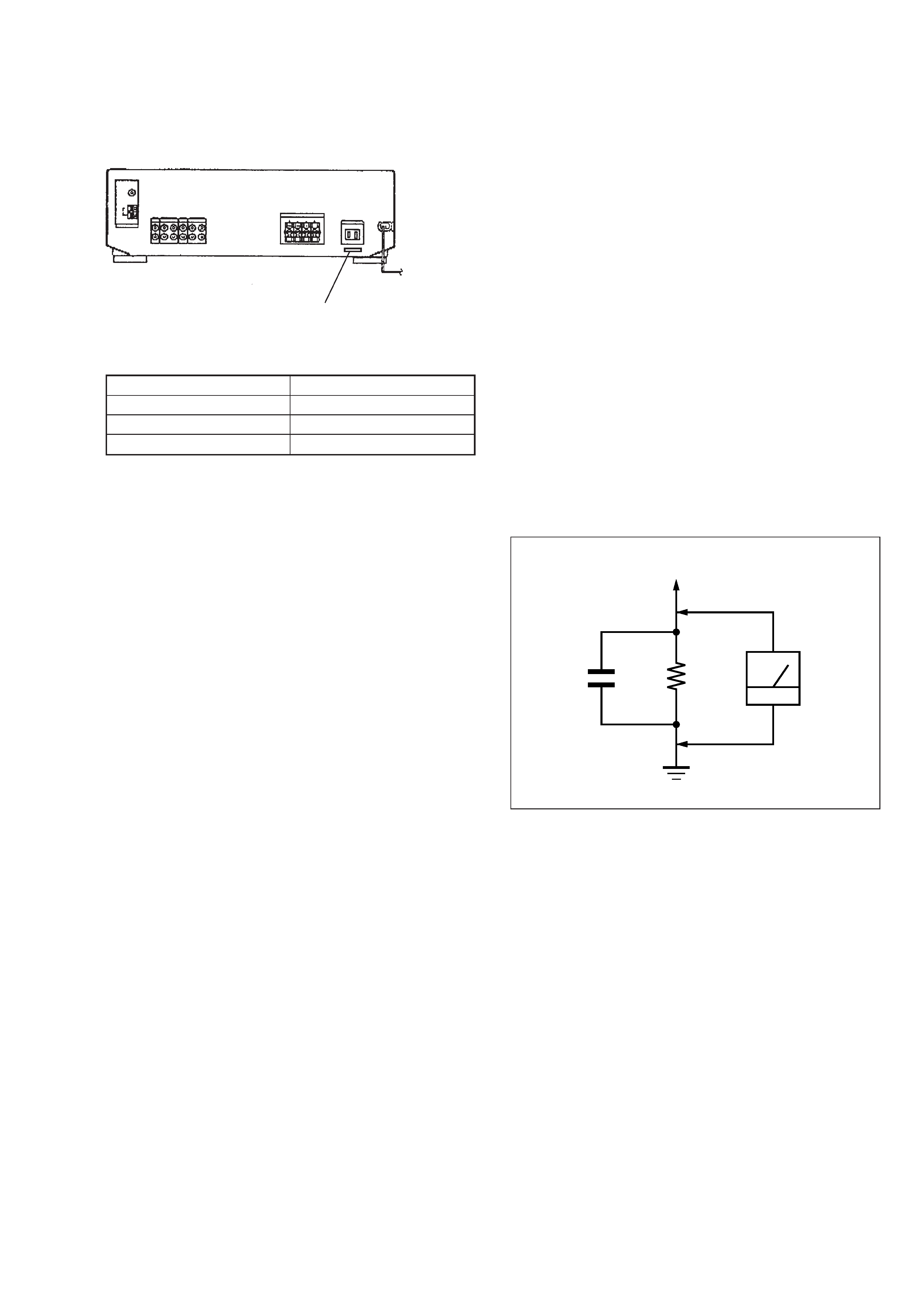
MODEL IDENTIFICATION
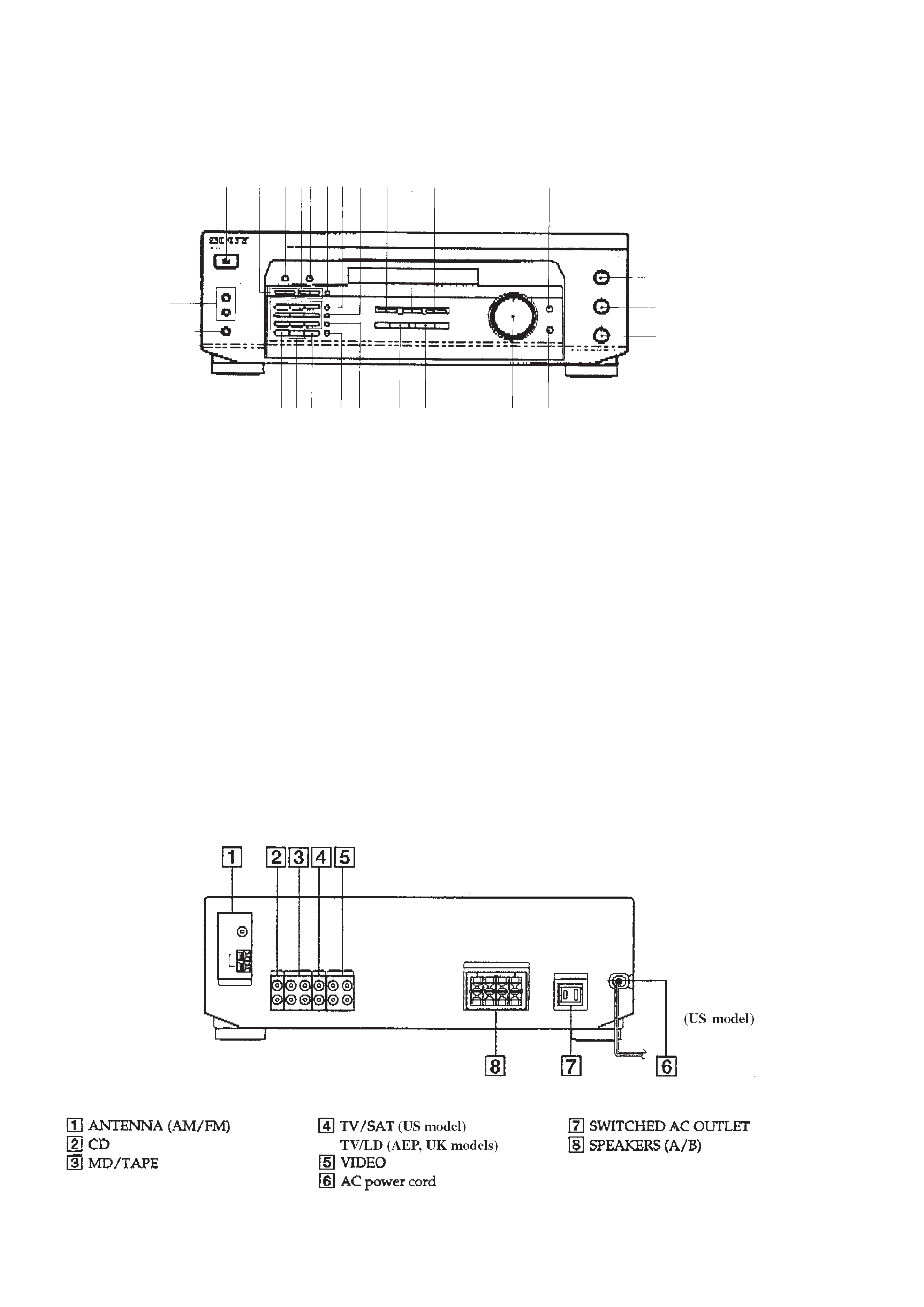
Rear view
12345
PART No.
MODEL
PART No.
US model
4-216-802-0
AEP model
4-216-802-1
UK model
4-216-802-2
SAFETY CHECK-OUT
After correcting the original service problem, perform the follow-
ing safety check before releasing the set to the customer:
Check the antenna terminals, metal trim, "metallized" knobs,
screws, and all other exposed metal parts for AC leakage.
Check leakage as described below.
LEAKAGE TEST
The AC leakage from any exposed metal part to earth ground and
from all exposed metal parts to any exposed metal part having a
return to chassis, must not exceed 0.5 mA (500 microampers.).
Leakage current can be measured by any one of three methods.
1. A commercial leakage tester, such as the Simpson 229 or RCA
WT-540A. Follow the manufacturers' instructions to use these
instruments.
2. A battery-operated AC milliammeter. The Data Precision 245
digital multimeter is suitable for this job.
3. Measuring the voltage drop across a resistor by means of a
VOM or battery-operated AC voltmeter. The "limit" indica-
tion is 0.75 V, so analog meters must have an accurate low-
voltage scale. The Simpson 250 and Sanwa SH-63Trd are ex-
amples of a passive VOM that is suitable. Nearly all battery
operated digital multimeters that have a 2 V AC range are suit-
able. (See Fig. A)
Fig. A.
Using an AC voltmeter to check AC leakage.
1.5 k
0.15
µF
AC
voltmeter
(0.75 V)
To Exposed Metal
Parts on Set
Earth Ground
4
SECTION 2
GENERAL
1 I/u button
2 TUNING +, buttons
(US model)
TUNING/CHAR +, buttons
(AEP, UK models)
3 NAME button
(AEP, UK models)
4 PRESET/TUNING +, buttons
(US model)
PRESET/PTY SELECT +, buttons
(AEP, UK models)
5 DISPLAY button (AEP, UK models)
6 RDS PTY button
(AEP, UK models)
7 AM button
(US model)
RDS EON button
(AEP, UK models)
Location of controls
· Front view
8 FM button
(US model)
FM/AM button
(AEP, UK models)
9 VIDEO button
0 TV/SAT button
(US model)
TV/LD button
(AEP, UK models)
!¡ MD/TAPE button
!TM BASS BOOST button and indicator
!£ SPEAKERS A, B ON/OFF buttons
!¢ PHONES jack
! SHIFT button
!§ Numeric buttons
!¶ DIRECT button
!· MEMORY button
(US model)
MEMORY/ENTER button
(AEP, UK models)
!ª FM MODE button
@º TUNER button
@¡ CD button
@TM VOLUME control
@£ MUTING button and indicator
@¢ TREBLE control
@ BASS control
@§ BALANCE control
345
1
2
67
!
8 9 0 !¡
!TM
!£
!¢
!§!¶ !· !ª
@º @¡
@TM
@£
@¢
@
@§
· Rear view
5
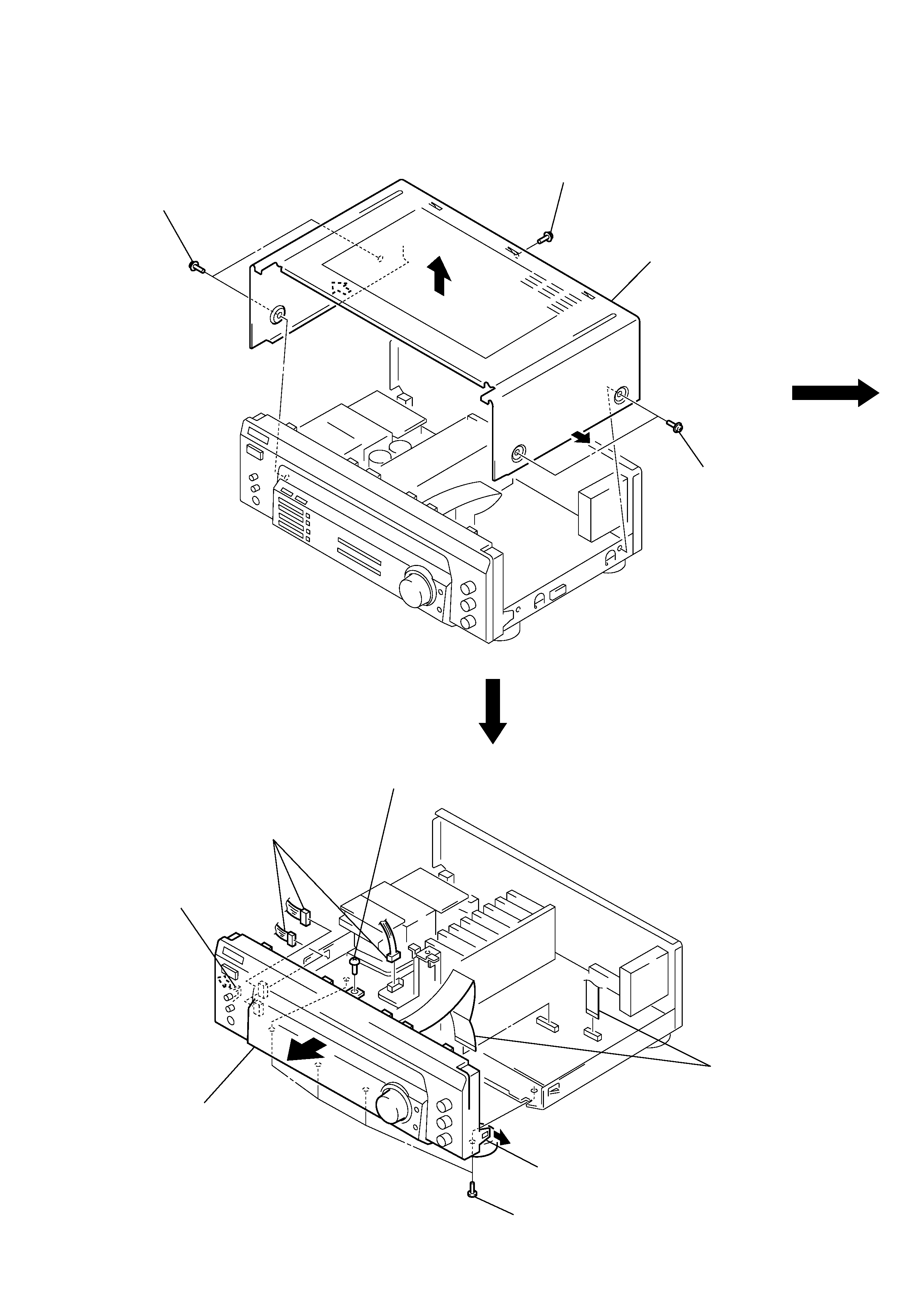
CASE
FRONT PANEL SECTION
Note: Follow the disassembly procedure in the numerical order given.
SECTION 3
DISASSEMBLY
1 two tapping screws
1 tapping screw
2 case
1 two tapping screws
2 three connectors
(CNP702 704)
3 screw
(BVTP3
× 8)
4 claw
5 front panel
section
3 four screws
(BVTP3
× 8)
4 claw
1 two flat wires
(CNS204, CNP404)