FM STEREO/FM-AM RECEIVER
MICROFILM
US Model
Canadian Model
Australian Model
Audio power specificaitons
POWER OUTPUT AND TOTAL
HARMONIC DISTORTION
With 8-ohm loads both channels
driven, from 20 - 20,000 Hz; rated 120
watts per channel minimum RMS
power, with no more than 0.05 % total
harmonic distortion from 250 miliwatts
to rated output (US model only).
Amplifier section
POWER OUTPUT
Stereo mode
8 ohms 20 Hz - 20 kHz,
THD 0.05 %,
120 W + 120 W
Surround mode
(8 ohms at 1 kHz, THD
0.05 %)
Front: 120 W + 120 W
Center*: 120 W
Rear*: 120 W + 120 W
* No sound may be out-
put when using certain
sound sources and/or
sound mode settings.
SPECIFICATIONS
SERVICE MANUAL
STR-DA90ESG
Manufactured under license from Dolby
Laboratories Licensing Corporation.
"Dolby," the double-D symbol
a, "AC-3" and
"Pro Logic" are trademarks of Dolby Labo-
ratories Licensing Corporation.
Dynamic power
165 W + 165 W, 8 ohms
output (US,
280 W + 280 W, 4 ohms
Canadian model)
Harmonic
Less than 0.05 %
distortion at
(Direct Pass)
rated output
Frequency
PHONO: RIAA
response
equalization curve
±0.5 dB
CD, TAPE, DAT/MD,
LD, DVD, TV/DBS,
VIDEO: 10 Hz - 50
kHz
dB
(Direct Pass)
Input (ANALOG)
Sensitivity
Impedance
S/N
PHONO
2.5 mV
50
75 dB*
kilohms
(A, 2.5 mV)
CD, TAPE,
DAT/MD,
VIDEO,
200 mV
50
82 dB*
LD/DVD,
kilohms
(A, 200mV)
TV/DBS
+0.5
2
Input (DIGITAL)
Sensitivity
Impedance
S/N
LD/DVD
75 ohms
100 dB
AC-3 RF
(A, 20 kHz LPF)
LD/DVD
75 ohms
100 dB
COAXIAL
(A, 20 kHz LPF)
LD/DVD,CD,
DAT/MD,
100 dB
TV/DBS,
(A, 20 kHz LPF)
OPTICAL
* '78 IHF
Outputs
REC OUT:
DAT/MD, TAPE
Voltage: 200 mV
Impedance: 1 kilohms
AUDIO OUT:
VIDEO 1, 2
Voltage: 200mV
Impedance: 1 kilohms
PRE OUT
Voltage: 2V
Impedance: 1 kilohms
PHONES: Accepts low
and high impedance
headphones
BASS BOOST
+6 dB at 70 Hz
Continued on page 2

2
Digital Signal Processor section
Modulation
High Density Linear
(A/D conversion)
Converter
Demodulation
High Density Linear
(D/A conversion)
Converter (Advanced
Pulse D/A converter)
Sampling
48 kHz
frequency
Surround
LFE MIX
MUTE, 20 ~ 0 dB, 0.5
dB step
D.RANGE COMP
OFF, 0.1 ~ 0.9, STD,
MAX
REAR level
20 ~ +10 dB, 0.5 dB
step
CENTER level
20 ~ +10 dB, 0.5 dB
step
SUB WOOFER level
20 ~ +10 dB, 0.5 dB
step
WALL
17-step adjustable
SEAT
L/R 17-step adjustable
F/R 17-step adjustable
EFFECT
21-step adjustable
REVERB time
17-step adjustable
Equalizer
Band
BASS/TREBLE
Turnover frequency
BASS: 99 Hz ~ 992 Hz
TREBLE: 1.0 kHz ~
8.6 kHz
Level
±10 dB, 0.5 dB step
+0.5
2
FM tuner section
Tuning range
87.5 - 108.0 MHz
Antenna
75 ohms, unbalanced
terminals
Sensitivity
Mono: 18.3 dBf, 4.5 µV
Stereo: 38.3 dBf, 45 µV
Usable sensitivity
11.2 dBf, 2 µV (IHF)
S/N
Mono: 76 dB
Stereo : 70 dB
Harmonic
Mono: 0.3 %
distortion at
Stereo: 0.5 %
1 kHz
Separation
45 dB at 1 kHz
Frequency
30 Hz - 15 kHz
dB
response
Selectivity
60 dB at 400 kHz
AM tuner section
Tuning range
With 10 kHz interval*:
530 - 1710 kHz
US, Canadian model
With 9 kHz interval:
531 - 1710 kHz
US, Canadian model
531 - 1602kHz
Australian model
Antenna
Loop antenna
Usable sensitivity
50 dB/m (at 1,000 kHz or
999 kHz)
S/N
54 dB (at 50 mV/m)
Harmonic
0.5 % (50 mV/m,
distortion
400 kHz)
Selectivity
At 9 kHz: 35 dB
At 10 kHz: 40 dB
* You can change the AM tuning interval be-
tween 9 kHz and 10 kHz. After tuning in any
AM station, turn off the receiver. While hold-
ing down the PRESET + button, press the
POWER switch. When you change the inter-
val, all the preset stations will be erased. To
reset the interval, repeat the same procedure.
US, Canadian model
Video section
Inputs
VIDEO:
1 Vp-p 75 ohms
S-VIDEO:
Y: 1 Vp-p 75 ohms
C: 0.286 Vp-p 75 ohms
Outputs
VIDEO:
1 Vp-p 75 ohms
S-VIDEO:
Y: 1 Vp-p 75 ohms
C: 0.286 Vp-p 75 ohms
General
System
Tuner section:
PLL quartz-locked
digital synthesizer sys-
tem
Preamplifier section:
Low-noise NF type
equalizer
Power amplifier section:
Pure-complimentary
Parallel P.P.
Power
Australian models:
requirements
240 V AC, 50 Hz
US, Canadian models:
120 V AC, 60 Hz
Power
Australian models: 430 W
consumption
US models: 385 W
Canada models: 550 VA
AC outlets
Australian models:
1 switched, total 100 W
US, Canadian models:
2 switched, total 120 W
Dimensions
430
× 160 × 435 mm
(17
× 63/
8
× 171/
4
inches)
Mass (Approx.)
16.0 kg (35 lb 4 oz)
Supplied
· FM wire antenna (1)
accessories
· AM loop antenna (1)
· Remote commander
(remote) (1)
(remote for US and
Canadian models:
RM-H501)
(Remote for Australian
model: RM-VR101)
· Size AA (R6) batteries
(2)
· IR repeater (1)
Design and specifications are subject to change
without notice.
3
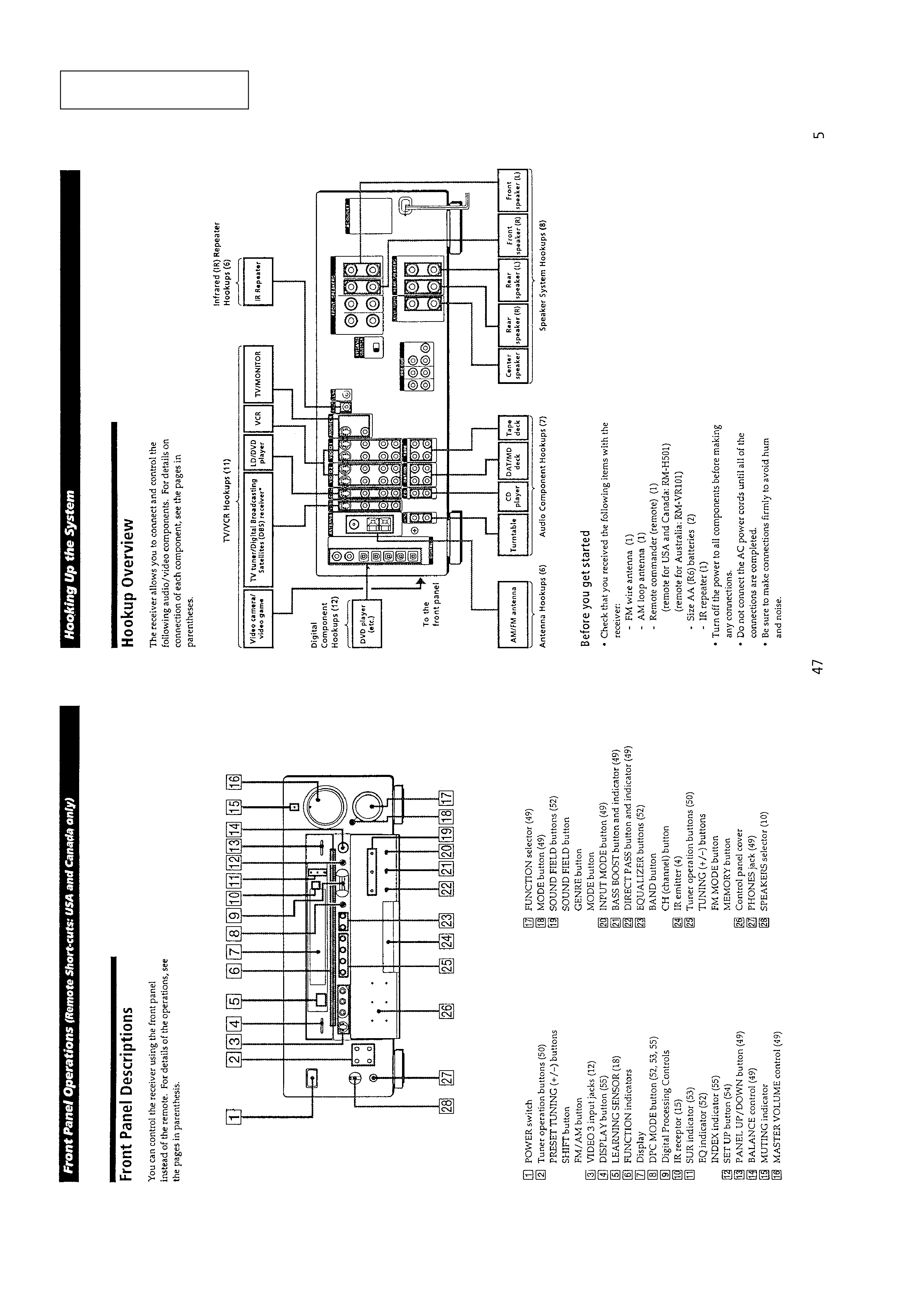
TABLE OF CONTENTS
1.
GENERAL ................................................................... 4
2.
DISASSEMBLY .......................................................... 5
3.
ELECTRICAL ADJUSTMENTS ......................... 7
4.
DIAGRAMS
4-1. IC Pin Function Description ............................................ 9
4-2. Printed Wiring Boards DISPLAY Section ................ 27
4-3. Schematic Diagram DISPLAY Section .................... 31
4-4. Schematic Diagram VIDEO Section ......................... 36
4-5. Printed Wiring Boards VIDEO Section .................... 41
4-6. Schematic Diagram
INPUT/TUNER/POWER Section ............................. 45
4-7. Printed Wiring Boards
INPUT/TUNER/POWER Section ............................. 49
4-8. Schematic Diagram DIGITAL Section ...................... 54
4-9. Printed Wiring Board DIGITAL Section .................. 59
4-10. Schematic Diagram AMP/OUTPUT Section ............ 63
4-11. Printed Wiring Boards AMP/OUTPUT Section ....... 67
5.
EXPLODED VIEWS ................................................ 75
6.
ELECTRICAL PARTS LIST ................................ 79
SAFETY-RELATED COMPONENT WARNING!!
COMPONENTS IDENTIFIED BY MARK
! OR DOTTED LINE
WITH MARK
! ON THE SCHEMATIC DIAGRAMS AND IN
THE PARTS LIST ARE CRITICAL TO SAFE OPERATION.
REPLACE THESE COMPONENTS WITH SONY PARTS WHOSE
PART NUMBERS APPEAR AS SHOWN IN THIS MANUAL
OR IN SUPPLEMENTS PUBLISHED BY SONY.
ATTENTION AU COMPOSANT AYANT RAPPORT
À LA SÉCURITÉ!
LES COMPOSANTS IDENTIFIÉS PAR UNE MARQUE
! SUR
LES DIAGRAMMES SCHÉMATIQUES ET LA LISTE DES
PIÈCES
SONT
CRITIQUES
POUR
LA
SÉCURITÉ
DE
FONCTIONNEMENT. NE REMPLACER CES COM- POSANTS
QUE PAR DES PIÈCES SONY DONT LES NUMÉROS SONT
DONNÉS DANS CE MANUEL OU DANS LES SUPPLÉMENTS
PUBLIÉS PAR SONY.
MODEL IDENTIFICATION
BACK PANEL
US Model
: 0
Canadian Model : 1
Australian Model : 2
SAFETY CHECK-OUT
After correcting the original service problem, perform the follow-
ing safety check before releasing the set to the customer:
Check the antenna terminals, metal trim, "metallized" knobs,
screws, and all other exposed metal parts for AC leakage.
Check leakage as described below.
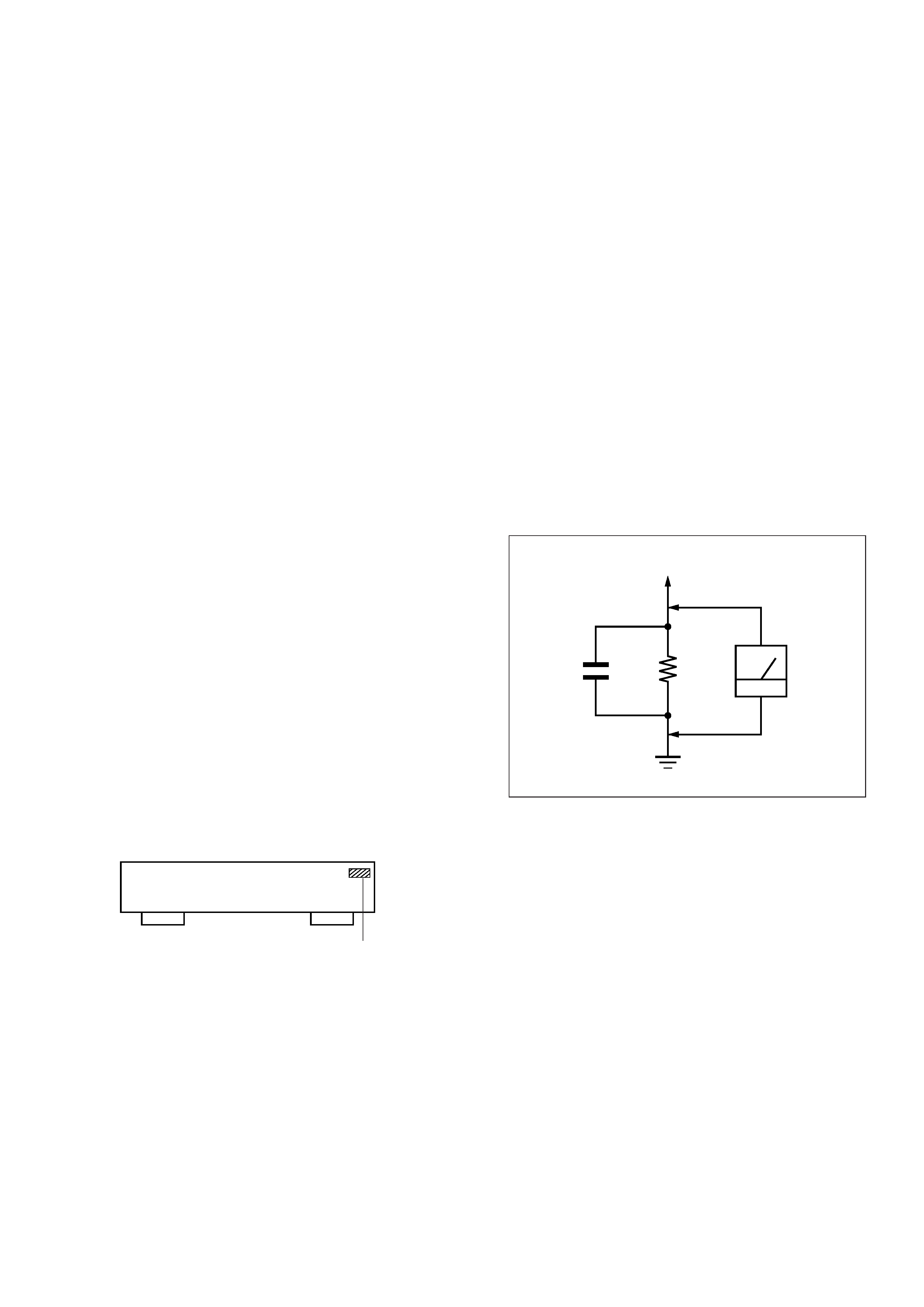
LEAKAGE TEST
The AC leakage from any exposed metal part to earth ground and
from all exposed metal parts to any exposed metal part having a
return to chassis, must not exceed 0.5 mA (500 microampers.).
Leakage current can be measured by any one of three methods.
1. A commercial leakage tester, such as the Simpson 229 or RCA
WT-540A. Follow the manufacturers' instructions to use these
instruments.
2. A battery-operated AC milliammeter. The Data Precision 245
digital multimeter is suitable for this job.
3. Measuring the voltage drop across a resistor by means of a
VOM or battery-operated AC voltmeter. The "limit" indica-
tion is 0.75 V, so analog meters must have an accurate low-
voltage scale. The Simpson 250 and Sanwa SH-63Trd are ex-
amples of a passive VOM that is suitable. Nearly all battery
operated digital multimeters that have a 2 V AC range are suit-
able. (See Fig. A)
Fig. A.
Using an AC voltmeter to check AC leakage.
1.5 k
0.15
µF
AC
voltmeter
(0.75 V)
To Exposed Metal
Parts on Set
Earth Ground
4-991-373-
4
This section is extracted from
instruction manual.
SECTION 1
GENERAL
5
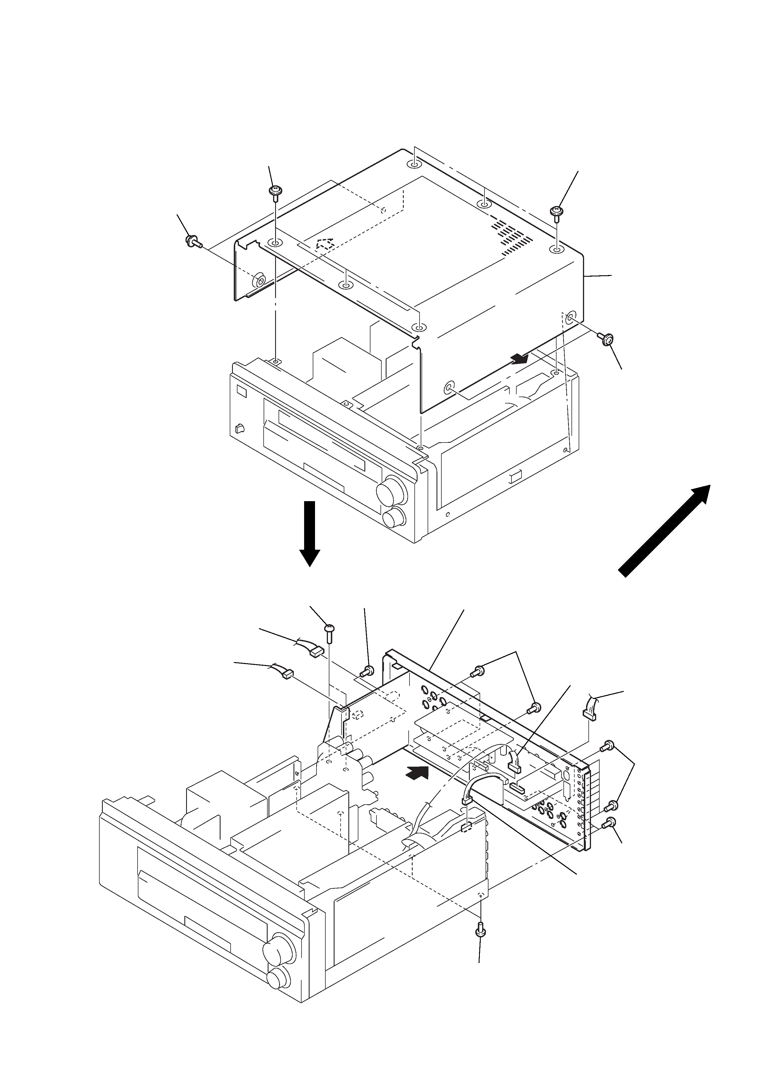
Note: Follow the disassembly procedure in the numerical order given.
CASE
SECTION 2
DISASSEMBLY
REAR PANEL SECTION
1 three screws
(M 3
× 8)
1 two screws
(M 3
× 8)
1 three screws
(M 3
× 8)
1 two screws
(M 3
× 8)
2
3 case
2
2 four screws
(BVTP 3
× 8)
1 connector
(CNV902)
1 connector
(CNE910)
1 connector
(CND802)
1 connector
(CNE807)
1 connector
(CND3503)
2 seven screws
(BVTP 3
× 8)
2 ten screws
(BVTP 3
× 8)
2 seven screws
(BVTP 3
× 8)
2 screw
(BVTP 3
× 8)
4 back panel section
3 two screws
(BVTP 3
× 6)