STR-DA30ES/DA50ES/V55ES
US Model
Canadian Model
STR-DA30ES/DA50ES
AEP Model
UK Model
E Model
Australian Model
PX Model
STR-DA50ES
Chinese Model
STR-V55ES
SERVICE MANUAL
FM STEREO FM-AM RECORDER
-- Continued on next page --
SPECIFICATIONS
Ver 1.1 2001. 06
Sony Corporation
Home Audio Company
Shinagawa Tec Service Manual Production Group
9-922-946-12
2001F1600-1
© 2001.6
Photo : STR-DA50ES
Manufactured under license from Dolby Laboratories Licensing
Corporation.
DOLBY, the double-D symbol
a , AC-3, the Dolby Digital and
"PRO LOGIC" are trademarks of Dolby Laboratories Licensing
Corporation.
AUDIO POWER SPECIFICATIONS
POWER OUTPUT AND TOTAL HARMONIC DISTORTION:
With 8 ohm loads, both channels driven, from 20 - 20,000
Hz; rated 120 watts (80 watts: DA30ES) per cannel minimum RMS
power, with no more than 0.05% total harmonic distortion from 250
milliwatts to rated output (USA model only).
Amplifier section
POWER OUTPUT
Stereo mode
(8 ohms 20 Hz 20 kHz, THD 0.05%)
120 W + 120 W (DA50ES/V55ES)
80W + 80W (DA30ES)
(4 ohms 20 Hz 20 kHz, THD 0.05%)
100 W + 100 W (DA50ES/V55ES)
70W + 70W (DA30ES)
Surround mode
(8 ohms at 1 kHz, THD 0.05%)
Front: 120W + 120W (DA50ES/V55ES)
80W + 80W (DA30ES)
Centera): 120W (DA50ES/V55ES)
80W (DA30ES)
Reara): 120W + 120W (DA50ES/V55ES)
80W + 80W (DA30ES)
(4 ohms at 1kHz, THD 0.05%)
Front: 100W + 100W (DA50ES/V55ES)
70W + 70W (DA30ES)
Centera): 100W (DA50ES/V55ES)
70W (DA30ES)
Reara): 100W + 100W (DA50ES/V55ES)
70W + 70W (DA30ES)
a) Depending on the sound field settings and the source, there may be no
sound output.
Frequency response
PHONO: RIAA
equalization curve
±0.5 dB
CD, TAPE, MD/DAT, DVD/LD, DVD TV/DBS, TV/LD,
VIDEO 1, 2, and VIDEO 3:
10 Hz - 50 kHz +0.5/-2 dB (with sound field, tone,
and bass booster bypassed)
Inputs (Analog) PHONO:
Sensitivity: 2.5 mV
Impedance: 50 kilohms
S/Nb): 75 dB (A, 2.5 mVc))
CD, DVD/LD, DVD/TAPE, MD/DAT. TV/
DBS, TV/LD, 5.1 INPUT, VIDEO 1, 2, AND VIDEO 3:
Sensitivity: 150 mV
Impedance: 50 kilohms
S/Nb): 82 dB (A, 150 mVc))
b) 78'IHF
c) Weighted network, input level
Inputs (Digital) DVD/LD, DVD (coaxial):
Sensitivity: 0.5 Vp-p
Impedance: 75 ohms
S/N: 100 dB (A, 20 kHz LPF)
CD, DVD/LD, DVD, TV/DBS,
TV/LD, MD/DAT (Optical):
S/N: 100 dB (A, 20 kHz LPF)
-- 2 --
Outputs (Analog)
TAPE, MD/DAT (REC OUT),
VIDEO 1, 2 (AUDIO OUT):
Voltage: 150 mV,
Impedance: 10 kilohms
FRONT L/R, CENTER, REAR L/R
WOOFER:
Voltage: 2 V
Impedance: 1 kilohms
PHONES:
Accepts low and high-impedance headphones
Outputs (Digital)
MD/DAT (Optical)
BASS BOOST
+6 dB at 70 Hz
Sampling Frequency
48 kHz
EQ
BASS: 100 Hz ~ 1.0kHz (21 steps)
MID: 500 Hz ~ 5.0kHz (21 steps)
TREBLE: 1.0 kHz ~ 10kHz (21 steps)
Gain levels: ±10 dB, 1 dB step
FM tuner section
Tuning range
87.5 108.0 MHz
Antenna terminals
75 ohms, unbalanced
Sensitivity
Mono: 18.3 dBf, 4.5 µV
Stereo: 38.3 dBf, 45 µV
Usable sensitivity
11.2 dBf, 2 µV (IHF)
S/N
Mono: 76 dB
Stereo: 70 dB
Harmonic distortion at 1 KHz
Mono: 0.3%
Stereo: 0.5%
Separation
45 dB at 1 kHz
Frequency response
30 Hz 15 kHz +0.5/-2 dB
Selectivity
60 dB at 400 kHz
AM tuner section
Tuning range
With 10-kHz tuning scale:
530 1710 kHz (USA/Canada)d)
530 1610 kHz (E)d)
With 9-kHz tuning scale:
531 1710 kHz (USA/Canada)d)
531 1602 kHz (all other countries)d)
Antenna
Loop antenna
Usable sensitivity
50 dB/m (at 1,000 kHz or 999 kHz)
S/N
54 dB (at 50 mV/m)
Harmonic distortion
0.5 % (50 mV/m, 400 kHz)
Selectivity
At 9 kHz: 35dB
At 10 kHz: 40 dB
d) You can change the AM tuning scale to 9 kHz (USA/Canada) or 10
kHz (all other countries). After tuning in any AM station, turn off the
receiver. Hold down the TUNING + button and press the 1/u button.
All preset stations will be erased when you change the tuning scale. To
reset the scale to 10 kHz (or 9 kHz), repeat theprocedure.
Video section
Inputs
S.VIDEO Y: 1 Vp-p 75 ohms
S.VIDEO C: 0.286 Vp-p 75 ohms
Outputs
S.VIDEO Y: 1 Vp-p 75 ohms
S.VIDEO C: 0.286 Vp-p 75 ohms
General
System
Tuner section:
PLL quartz-locked digital synthesizer system
Preamplifier section: Low-noise NF type equalizer
Power amplifier section: Pure-complementary SEPP
Power requirements
USA, Canadian: 120 V AC, 60 Hz
E, Saudi Arabia, PX: 120 or 220 or 240 V AC, 50/60 Hz
(Adjustable with voltage selector)
Other countries: 230 V 50/60 Hz
Power consumption
DA50ES USA, E: 380 W
DA50ES Canadian: 550 VA
DA30ES USA: 280 W
DA30ES Canadian: 400 VA
Other countries: 420 W
AC outlets
2 switched, total 100 W
Dimensions
430
× 160 × 410 mm (17 × 63/
8 × 16
1/
4 inches)
including projecting parts and controls
Mass (Approx.) DA50ES/V55ES: 16 Kg
DA30ES:
14 Kg
Supplied Accessories
FM wire antenna (1)
AM loop antenna (1)
Remote commander RM-TP501 (remote) (1)
LR6 (size-AA) alkaline batteries (4)
Design and specifications are subject to change without notice.
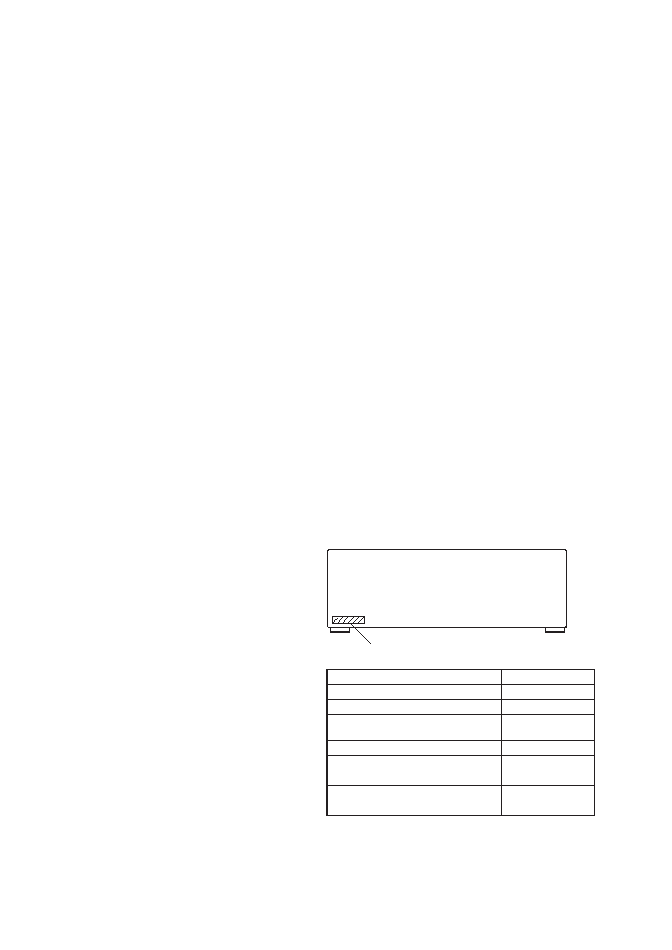
MODEL IDENTIFICATION
BACK PANEL
MODEL
DA50ES: US model
DA50ES: Canadian model
DA50ES: AEP, UK, German, East European,
Australian models
DA50ES: E, Saudi Arabia, PX models
DA50ES: Malaysia, Singapore models
V55ES:
Chinese model
DA30ES: US model
DA30ES: Canadian model
PARTS No.
4-900-653-0
4-900-653-1
4-900-653-2
4-900-653-3
4-900-653-4
4-900-653-5
4-900-653-6
4-900-653-7
PART NO.
-- 3 --
SERVICE NOTE ··························································· 4
1.
GENERAL ······································································ 5
2.
TEST MODE ···························································· 7
3.
ELECTRICAL ADJUSTMENTS ··························· 8
4.
DIAGRAMS
4-1.
Block Diagram -- Main Section -- ··································· 9
4-2.
Block Diagram -- Tuner Section -- ································ 11
4-3.
Block Diagram -- Power Section -- ······························· 13
4-4.
Circuit Boards Location ··················································· 15
4-5.
Schematic Diagram -- Digital Section (1/2) -- ·············· 17
4-6.
Schematic Diagram -- Digital Section (2/2) -- ·············· 19
4-7.
Printed Wiring Board -- Digital Section -- ···················· 21
4-8.
Printed Wiring Board -- Main Section -- ······················· 23
4-9.
Schematic Diagram -- Main Section (1/3) -- ················· 25
4-10. Schematic Diagram -- Main Section (2/3) -- ················· 27
4-11. Schematic Diagram -- Main Section (3/3) -- ················· 29
4-12. Schematic Diagram -- AMP Section -- ·························· 31
4-13. Printed Wiring Board -- AMP Section -- ······················· 33
4-14. Schematic Diagram -- Video Section -- ························· 35
4-15. Printed Wiring Board -- Video Section -- ······················ 37
4-16. Schematic Diagram -- Display Section -- ······················ 39
4-17. Printed Wiring Board -- Display Section -- ··················· 41
4-18. Schematic Diagram -- Speaker Section -- ····················· 43
4-19. Printed Wiring Board -- Speaker Section -- ··················· 45
4-20. Printed Wiring Board -- Audio Section -- ······················ 47
4-21. Schematic Diagram -- Audio Section -- ························ 49
4-22. Schematic Diagram -- Input Section -- ·························· 50
4-23. Printed Wiring Board -- Input Section -- ······················· 51
4-24. Schematic Diagram -- Power Section -- ························ 53
4-25. Printed Wiring Board -- Power Section -- ····················· 55
4-26. IC Block Diagrams ··························································· 57
4-27. IC Pin Function Description ············································· 61
5.
EXPLODED VIEWS
5-1.
Front Panel Section ·························································· 69
5-2.
Chassis Section ································································· 70
6.
ELECTRICAL PARTS LIST ··································· 72
SAFETY-RELATED COMPONENT WARNING!!
COMPONENTS IDENTIFIED BY MARK
! OR DOTTED LINE WITH
MARK
! ON THE SCHEMATIC DIAGRAMS AND IN THE PARTS
LIST ARE CRITICAL TO SAFE OPERATION. REPLACE THESE
COMPONENTS WITH SONY PARTS WHOSE PART NUMBERS
APPEAR AS SHOWN IN THIS MANUAL OR IN SUPPLEMENTS
PUBLISHED BY SONY.
ATTENTION AU COMPOSANT AYANT RAPPORT
À LA SÉCURITÉ!
LES COMPOSANTS IDENTIFÉS PAR UNE MARQUE
! SUR LES
DIAGRAMMES SCHÉMATIQUES ET LA LISTE DES PIÈCES SONT
CRITIQUES POUR LA SÉCURITÉ DE FONCTIONNEMENT. NE
REMPLACER CES COMPOSANTS QUE PAR DES PIÈSES SONY
DONT LES NUMÉROS SONT DONNÉS DANS CE MANUEL OU
DANS LES SUPPÉMENTS PUBLIÉS PAR SONY.
TABLE OF CONTENTS
After correcting the original service problem, perform the
following safety checks before releasing the set to the customer:
Check the antenna terminals, metal trim, "metallized" knobs, screws,
and all other exposed metal parts for AC leakage. Check leakage as
described below.
LEAKAGE
The AC leakage from any exposed metal part to earth ground and
from all exposed metal parts to any exposed metal part having a
return to chassis, must not exceed 0.5 mA (500 microampers).
Leakage current can be measured by any one of three methods.
1.
A commercial leakage tester, such as the Simpson 229 or RCA
WT-540A. Follow the manufacturers' instructions to use these
instruments.
2.
A battery-operated AC milliammeter. The Data Precision 245
digital multimeter is suitable for this job.
3.
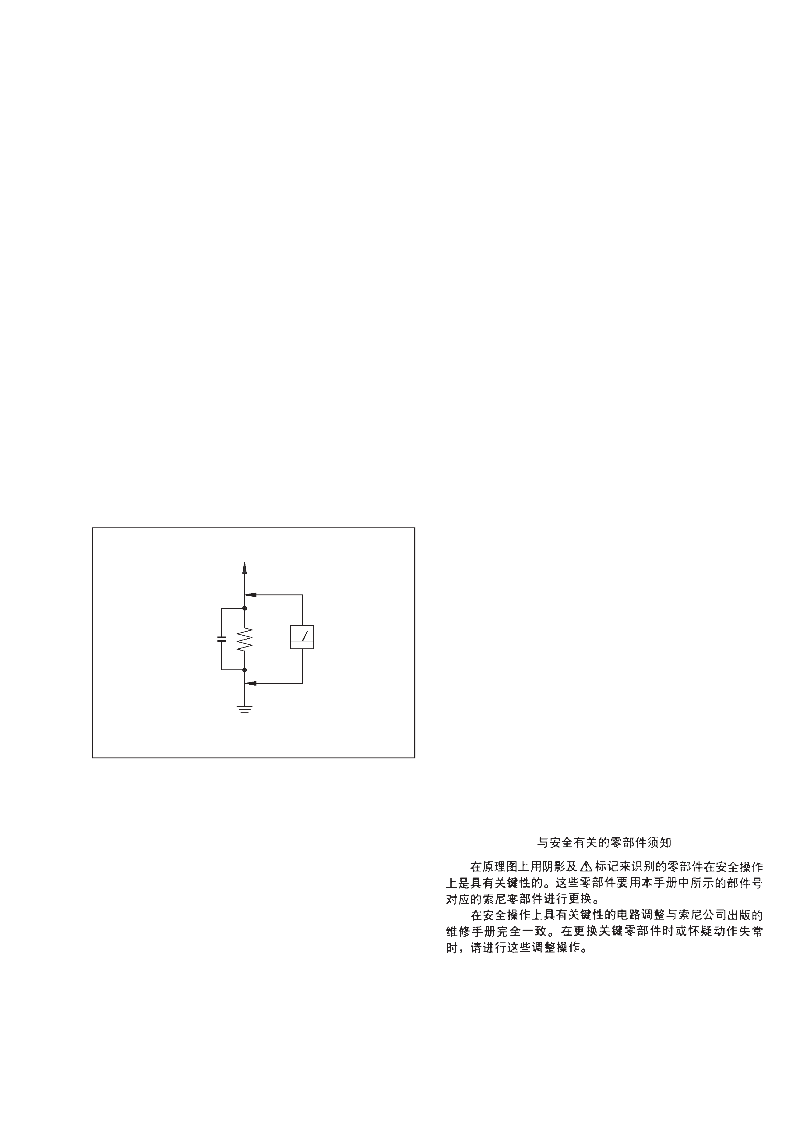
Measuring the voltage drop across a resistor by means of a
VOM or battery-operated AC voltmeter. The "limit" indication
is 0.75 V, so analog meters must have an accurate low-voltage
scale. The Simpson 250 and Sanwa SH-63Trd are examples of
a passive VOM that is suitable. Nearly all battery operated
digital multimeters that have a 2V AC range are suitable. (See
Fig. A)
SAFETY CHECK-OUT
To Exposed Metal
Parts on Set
0.15
µF
1.5 k
AC
Voltmeter
(0.75 V)
Earth Ground
Fig. A. Using an AC voltmeter to check AC leakage.
-- 4 --
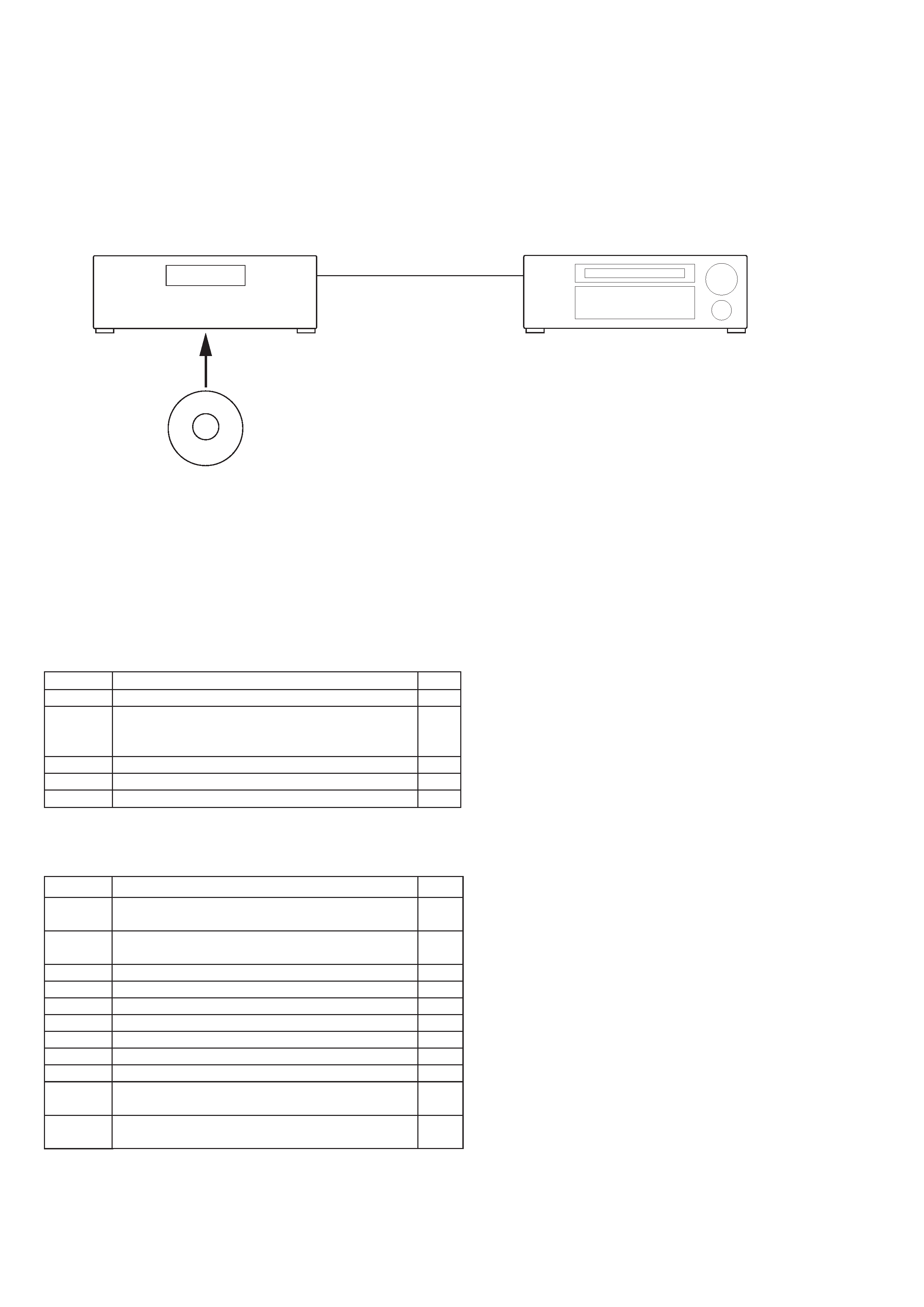
Track No.
1
2
3
4
5
SERVICE NOTE
DTS Decode Test
[Required Instrument]
CD player (equipped with optical digital output)
Optical cable
DTS test CD (J-2501-154-A)
Time
5'40"
4'16"
4'08"
3'29"
6'42"
[Music Demonstration]
Contents
Seal : "Prayer for the Dying"
Andrew Litton conducting
The Dallas Symphony Orchestra & Chorus:
Excerpt from Tchaikovsky: "1812 Overture"
Alan Parsons with Christopher Cross: "So Far Away"
Shoelss Joe: "The Bet"
TELARC: "A Touch of Surround Madness"
[Procedure]
1. Set the FUNCTION of the receiver to the CD position and confirm that "@OPTICAL@" and "CD" appear on the display.
2. Insert the DTS test CD into the CD player and play the CD.
3. About three seconds later, confirm that the receiver recognizes the optical signal and that the "DTS" and "dts [3/2]" are appear on the
display. Confirm also that MULTI CHANNEL DECODING (blue lamp) flashes on the front panel.
Time
1'00"
1'00"
2'00"
2'00"
2'00"
2'00"
2'00"
2'00"
2'00"
2'00"
2'00"
Track No.
6
7
8
9
10
11
12
13
14
15
16
[Set-Up]
Contents
1 kHz sine (All channels)
Level Adjustment and Harmonic Distortion Analysis
100 Hz sine (All channels)
Verification of Signal and Subwoofer Testing
C-Weighted Pink Noise-Left Front Channel
C-Weighted Pink Noise-Center Channel
C-Weighted Pink Noise-Right Front Channel
C-Weighted Pink Noise-Right Rear Channel
C-Weighted Pink Noise-Left Rear Channel
C-Weighted Pink Noise-Subwoofer (LEE)
C-Weighted Pink Noise-All Channels
10 Hz to 20 kHz Sine Sweep
An "All Channel" Frequency Response Test
20 Hz to 160 Hz sine sweep
A "Subwoofer" Low Frequency Response Test
* Track numbers from 8 to 14 are for Room Equalization and Channel Identification.
1 CD player
2 Optical
digital output
3 Optical input
Receiver STR-DA50ES
5 DTS test CD (Music Demonstration and Set Up Disc)
[Connection]
-- 5 --
SECTION 1
GENERAL
This section is extracted
from STR-DA50ES
instruction manual.