MICROFILM
ST-EX77
AEP Model
UK Model
E Model
SERVICE MANUAL
This set is the tuner section in
MHC-EX66,DHC-EX77MD/MD77.
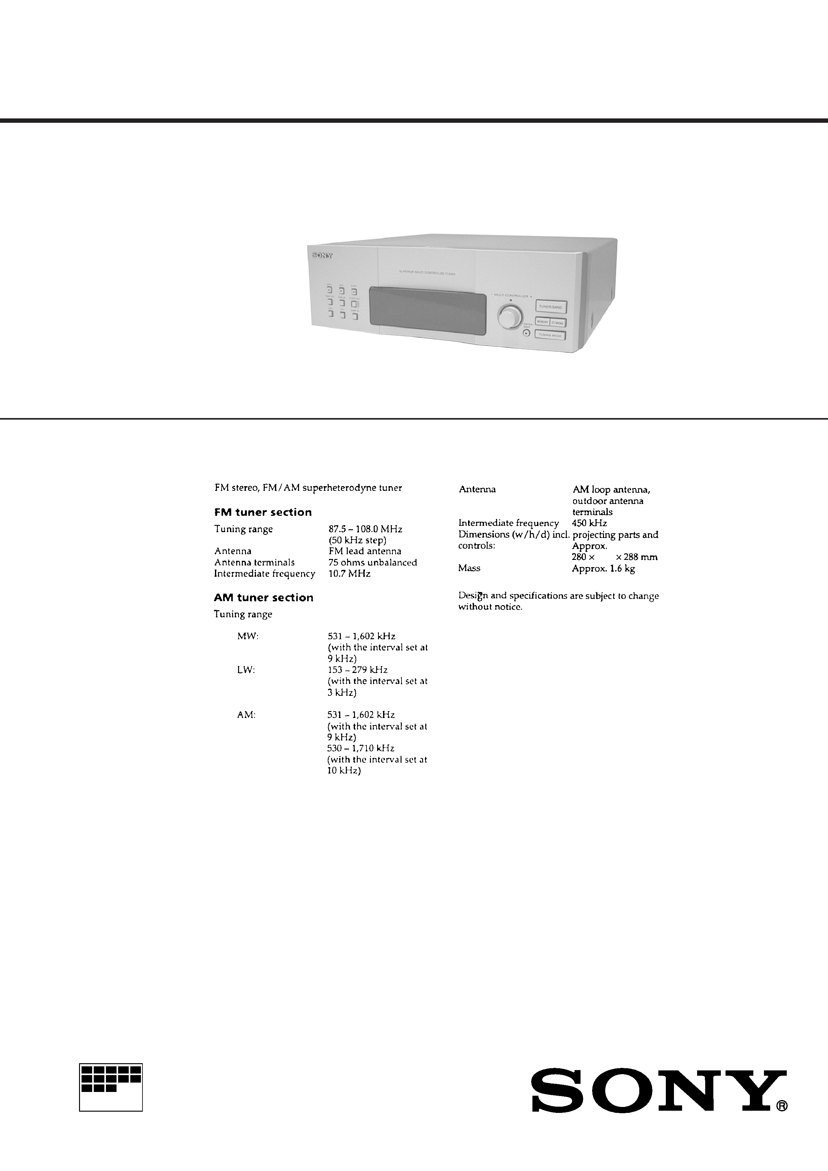
FM STEREO/FM-AM TIMER TUNER
SPECIFICATIONS
AEP, UK models:
Hong Kong, Singapore models:
90
2
TABLE OF CONTENTS
Servicing Notes ............................................................... 2
1.
GENERAL
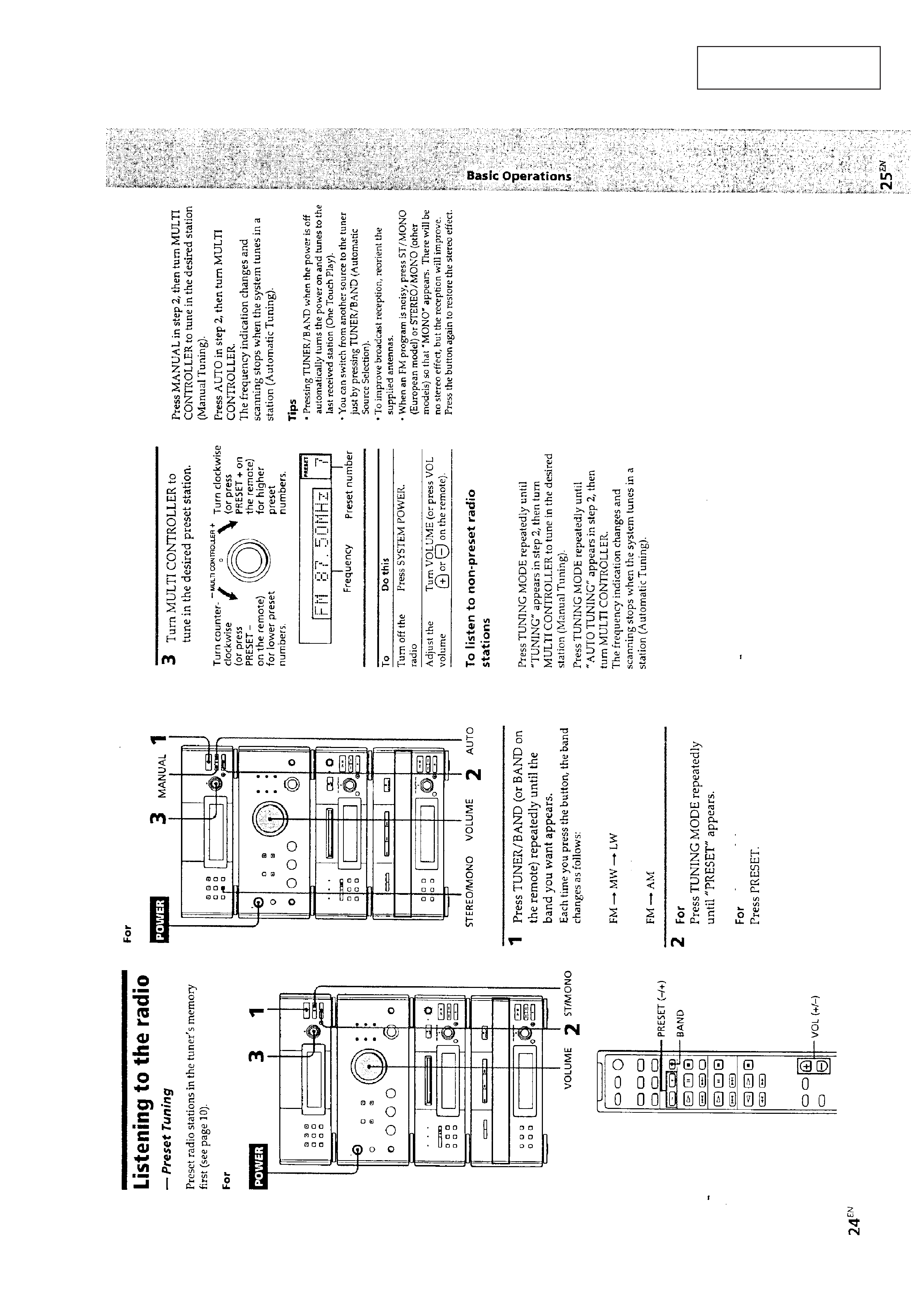
Listening to the Radio ....................................................
3
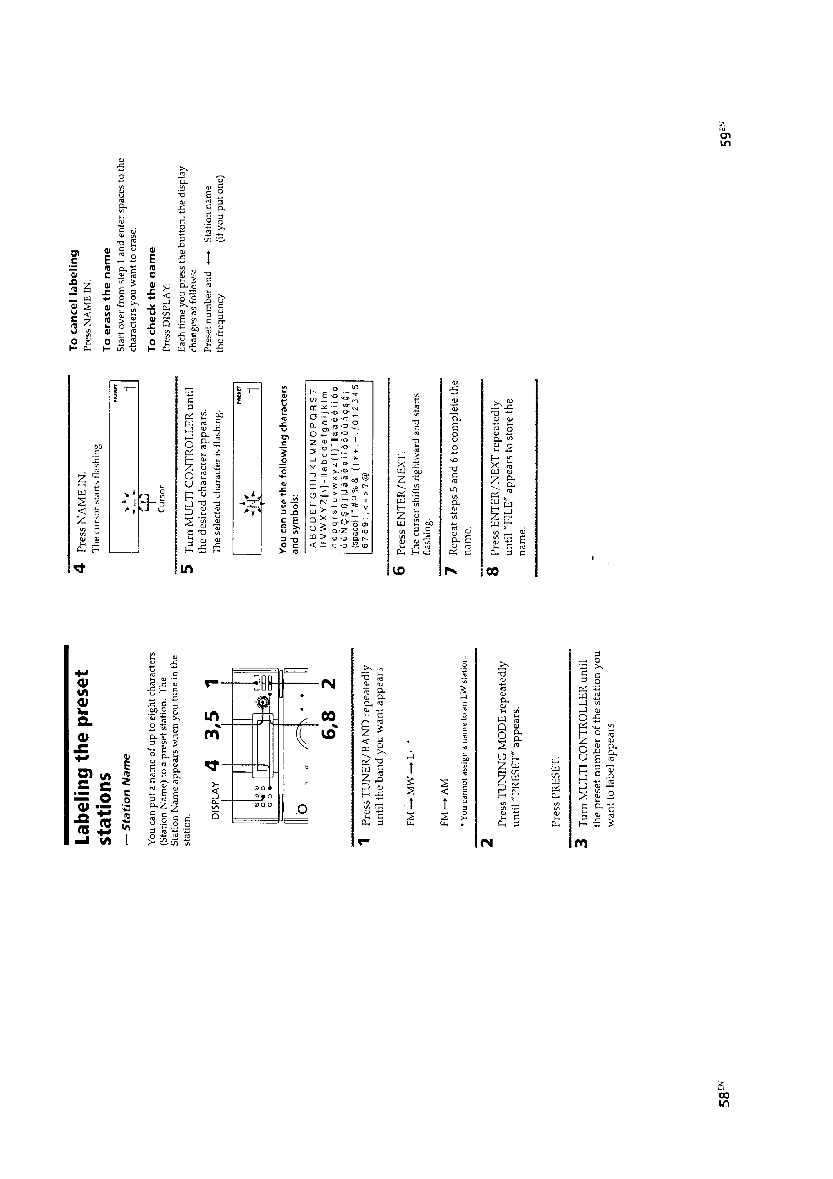
Labeling the Preset Stations ...........................................
4
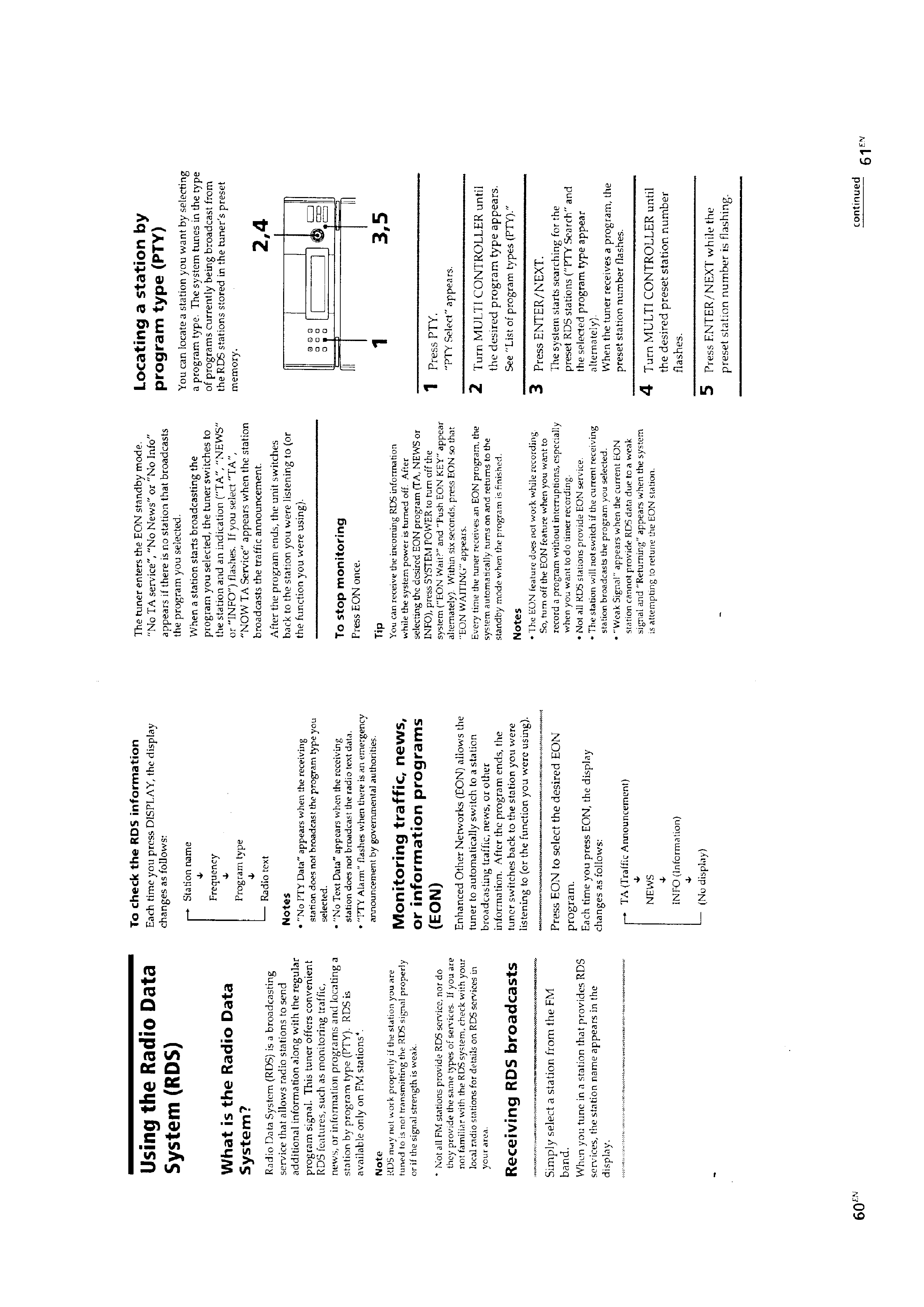
Using the Radio Data System (RDS) .............................
5
2.
DISASSEMBLY ........................................................
7
3.
ELECTRICAL ADJUSTMENTS .........................
8
4.
DIAGRAMS
4-1.
IC Pin Function Description ...........................................
9
4-2.
Printed Wiring Boards .................................................... 11
4-3.
Schematic Diagram ........................................................ 15
5.
EXPLODED VIEWS ................................................ 22
6.
ELECTRICAL PARTS LIST ................................. 24
SAFETY-RELATED COMPONENT WARNING!!
COMPONENTS IDENTIFIED BY MARK
! OR DOTTED LINE
WITH MARK
! ON THE SCHEMATIC DIAGRAMS AND IN
THE PARTS LIST ARE CRITICAL TO SAFE OPERATION.
REPLACE THESE COMPONENTS WITH SONY PARTS WHOSE
PART NUMBERS APPEAR AS SHOWN IN THIS MANUAL
OR IN SUPPLEMENTS PUBLISHED BY SONY.
MODEL IDENTIFICATION
Back Panel
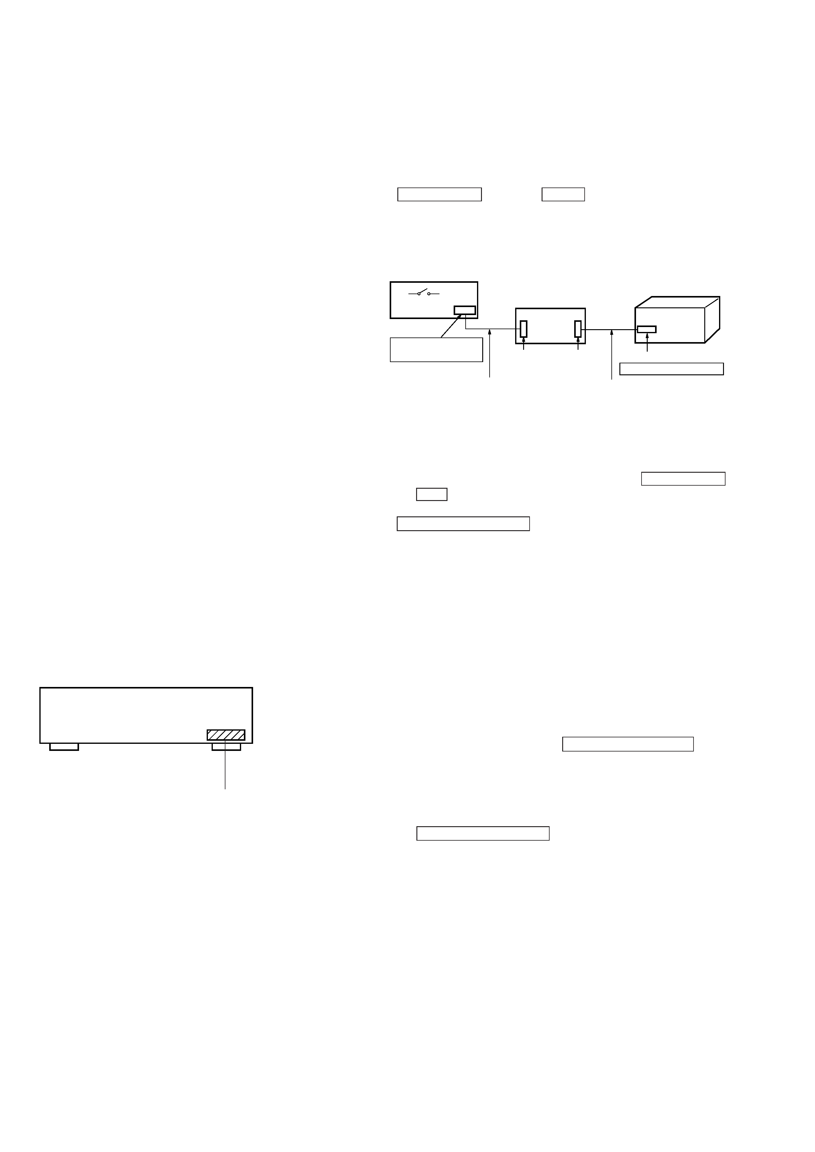
How to operate with a single unit.
Normally, this set is not operated with its own.
The exclusive jig (J-2501-078-A) and service box (PFJ-1) are nec-
essary to operate the set with a single unit.
Turn the power set of the service box ON. Then press the
ENTER/NEXT button and SLEEP button at the same time to
turn the power on.
Connection:
SERVICING NOTES
· KEY/FL tube/LED check mode.
To enter KEY/FL tube/LED check mode, press the ENTER/NEXT
and REC buttons at the same time.
Under mode, every time when press any key or turn
MULTI CONTROLLER knob, change to next situation.
1 All LED indicators light on
2 All FL tube indicators light on
3 A part of FL tube light on mode 1. (Indicated ST-SEG)
4 A part of FL tube light on mode 2. (Indicated RDS-SEG)
5 KEY check mode
Note:
1) All LED light on mode is kept, when buttons which is pressed
to enter all LED light on mode, release same time.
When release them separate timing, it is moved to next All
LED light on mode.
2) After all LED light on mode, light on point remove one by one,
when any button pressed or MULTI CONTROLLER knob
turned.
3) Under KEY check mode, every time buttons pressed numeri-
cal value of "KEY" in FL tube increase.
And that time, numerical value of "ECDR" increase when
MULTI CONTROLLER button turn to + direction, and it
decrease turn to direction.
When you want to finish this mode, unplug the power of amplifier
or turn off PFJ-1 of POWER switch.
4-985-904-1 : AEP, UK model
4-985-904-2 : Hong Kong, Singapore model
POWER SW
FH-E939, 838,937
CDP/TC
CN904
17P
CN902
7P
CN101 7P
JIG
(J-2501-078-A)
SERVICE BOX (PFJ-1)
SET
SYSTEM CONTROL
CORD WITH CONNECTOR 7P
(attached to set)
CORD WITH CONNECTOR 17P
(attached to PFJ-1)
3
This section is extracted
from instruction manual.
SECTION 1
GENERAL
AEP
,UK
models
AEP
,UK
models:
Hong
K
ong,
Singapore
models
Hong
K
ong,
Singapore
models:
Hong
K
ong,
Singapore
models:
AEP
,UK
models:
For
AEP
,UK
models:
For
Hong
K
ong,
Singapore
models:
4
For
Hong
K
ong,
Singapore
models:
Hong
K
ong,
Singapore
models:
AEP
,UK
models:
For
AEP
,UK
models:
5
(AEP
,UK
models
only)