MICROFILM
SERVICE MANUAL
HOME THEATER ACTIVE SPEAKER SYSTEM
US Model
Canadian Model
AEP Model
UK Model
E Model
SAVA-500/SS-CN16/SR16
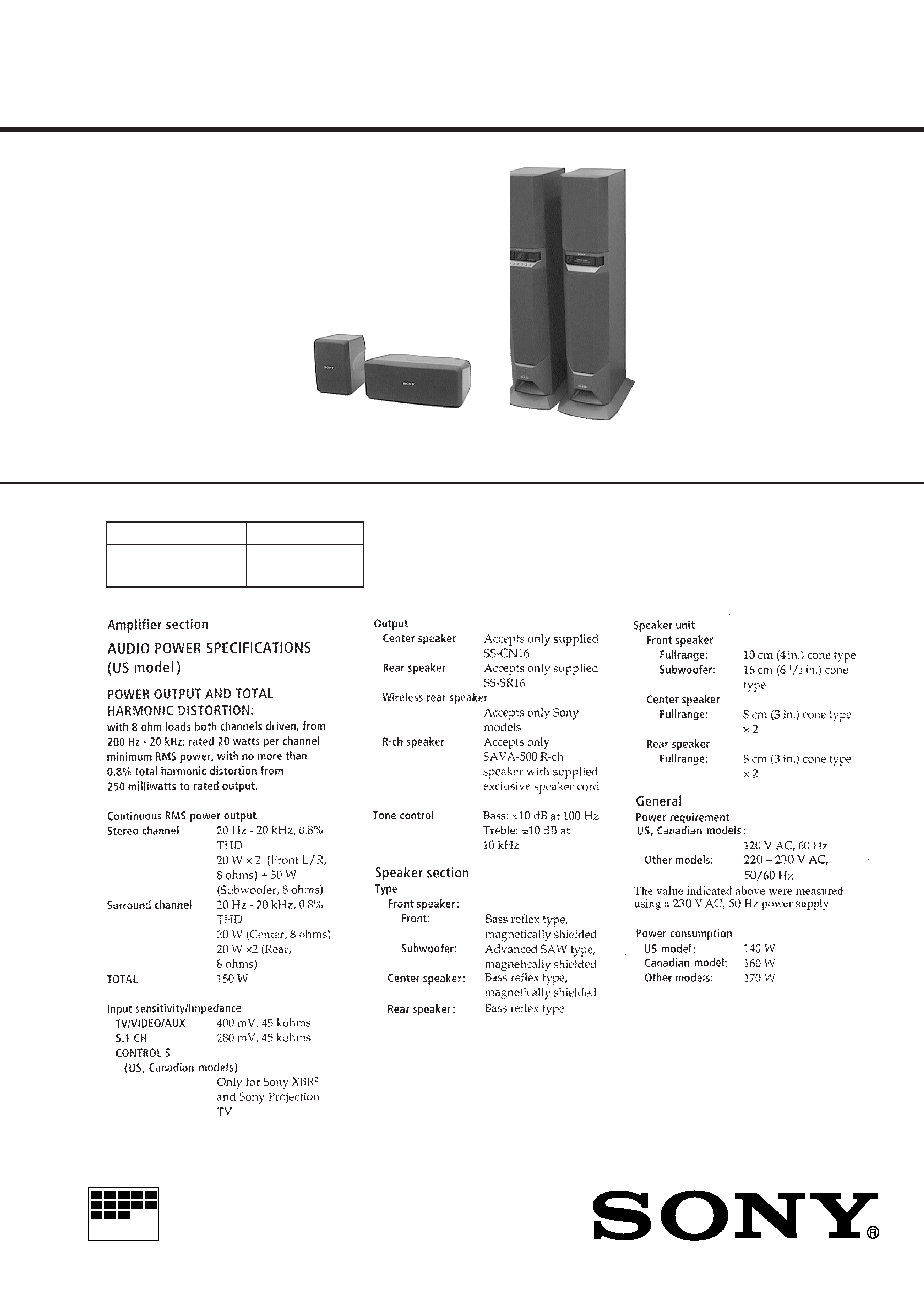
SPECIFICATIONS
Photo: SS-SR16
The SAVA-500 composed of the following table.
Continued on next page
Photo: SS-CN16
Photo: Main Unit
(L-ch)
(R-ch)
Front Speaker
Main Unit
Center Speaker
SS-CN16
Rear Speaker
SS-SR16

2
TABLE OF CONTENTS
1.
SERVICING NOTES ............................................... 3
2.
GENERAL ................................................................... 4
3.
DISASSEMBLY ......................................................... 5
4.
TEST MODE .............................................................. 8
5.
DIAGRAMS
5-1. Note for Printed Wiring Boards and
Schematic Diagrams ....................................................... 11
5-2. Printed Wiring Board MAIN Board ........................ 12
5-3. Schematic Diagram MAIN Board (1/3) ................... 13
5-4. Schematic Diagram MAIN Board (2/3) ................... 14
5-5. Schematic Diagram MAIN Board (3/3) ................... 15
5-6. Printed Wiring Boards FILTER/REG/T2/T1/
STANDBY/AC-SW Boards ......................................... 16
5-7. Schematic Diagram FILTER/REG/T2/T1/
STANDBY/AC-SW Boards ......................................... 17
5-8. Printed Wiring Board AMP (POW-SR/POW-SW/
POW-CN/POW-LR/CONNECTOR) Board ............... 18
5-9. Schematic Diagram AMP (POW-SR/POW-SW/
POW-CN/POW-LR/CONNECTOR) Board ............... 19
5-10. Printed Wiring Boards
DISPLAY/LED/KEY Boards ................................... 20
5-11. Schematic Diagram
DISPLAY/LED/KEY Boards ................................... 21
5-12. IC Pin Function Description ........................................... 24
6.
EXPLODED VIEWS ................................................ 26
7.
ELECTRICAL PARTS LIST ............................... 31
ATTENTION AU COMPOSANT AYANT RAPPORT
À LA SÉCURITÉ!
LES COMPOSANTS IDENTIFIÉS PAR UNE MARQUE
!
SUR LES DIAGRAMMES SCHÉMATIQUES ET LA LISTE
DES PIÈCES SONT CRITIQUES POUR LA SÉCURITÉ
DE FONCTIONNEMENT. NE REMPLACER CES COM-
POSANTS QUE PAR DES PIÈCES SONY DONT LES
NUMÉROS SONT DONNÉS DANS CE MANUEL OU
DANS LES SUPPLÉMENTS PUBLIÉS PAR SONY.
SAFETY-RELATED COMPONENT WARNING!!
COMPONENTS IDENTIFIED BY MARK
! OR DOTTED
LINE WITH MARK
! ON THE SCHEMATIC DIAGRAMS
AND IN THE PARTS LIST ARE CRITICAL TO SAFE
OPERATION. REPLACE THESE COMPONENTS WITH
SONY PARTS WHOSE PART NUMBERS APPEAR AS
SHOWN IN THIS MANUAL OR IN SUPPLEMENTS PUB-
LISHED BY SONY.
3
SECTION 1
SERVICING NOTES
MODEL IDENTIFICATION
Rear view
SAFETY CHECK-OUT
After correcting the original service problem, perform the follow-
ing safety check before releasing the set to the customer:
Check the antenna terminals, metal trim, "metallized" knobs,
screws, and all other exposed metal parts for AC leakage.
Check leakage as described below.
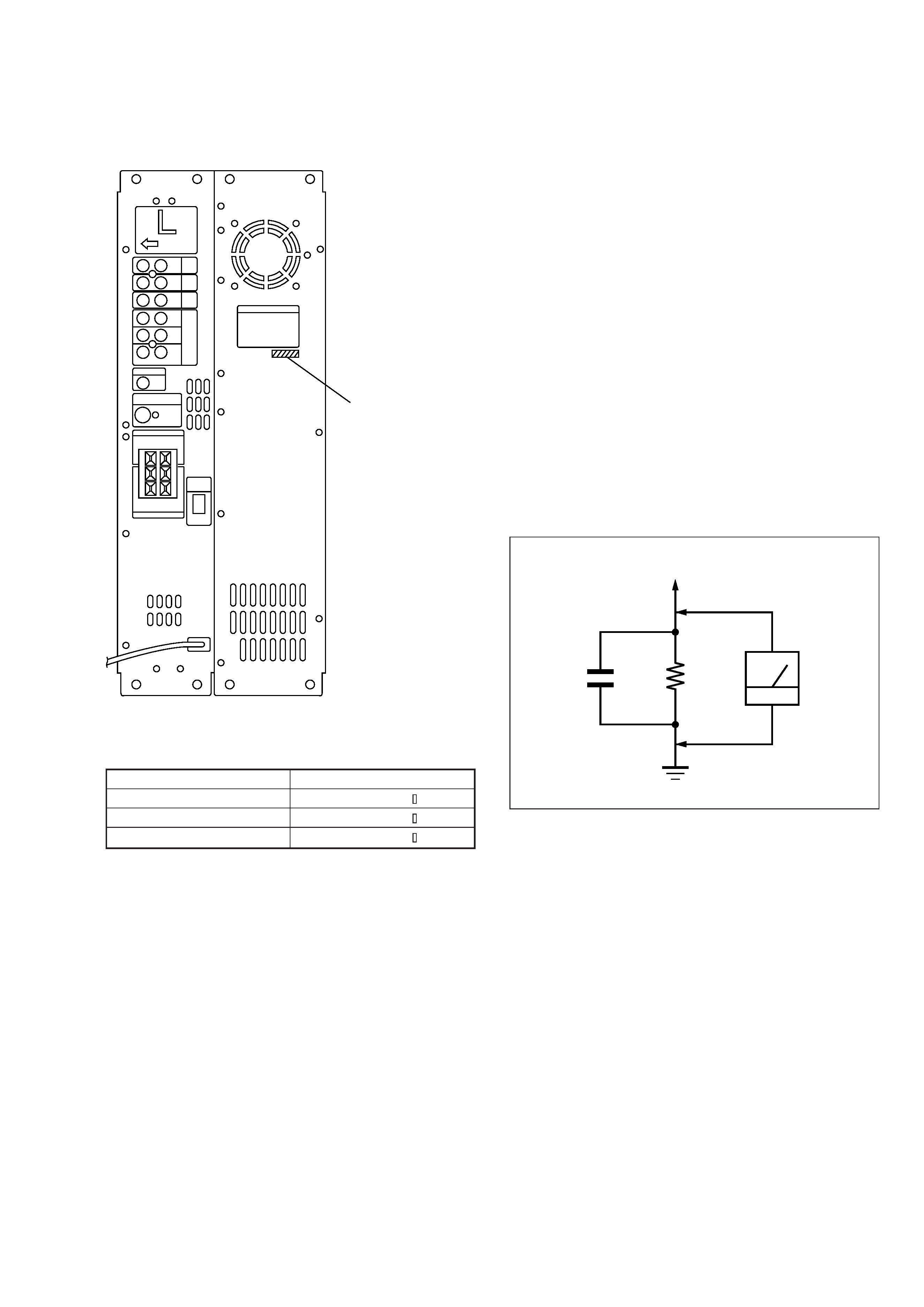
LEAKAGE TEST
The AC leakage from any exposed metal part to earth ground and
from all exposed metal parts to any exposed metal part having a
return to chassis, must not exceed 0.5 mA (500 microamperes).
Leakage current can be measured by any one of three methods.
1. A commercial leakage tester, such as the Simpson 229 or RCA
WT-540A. Follow the manufacturers' instructions to use these
instruments.
2. A battery-operated AC milliammeter. The Data Precision 245
digital multimeter is suitable for this job.
3. Measuring the voltage drop across a resistor by means of a
VOM or battery-operated AC voltmeter. The "limit" indica-
tion is 0.75 V, so analog meters must have an accurate low-
voltage scale. The Simpson 250 and Sanwa SH-63Trd are ex-
amples of a passive VOM that is suitable. Nearly all battery
operated digital multimeters that have a 2 V AC range are suit-
able. (See Fig. A)
Fig. A.
Using an AC voltmeter to check AC leakage.
1.5 k
0.15
µF
AC
voltmeter
(0.75 V)
To Exposed Metal
Parts on Set
Earth Ground
MODEL
PART No.
US model
4-217-252-3
Canadian model
4-217-252-4
EXCEPT US, Canadian models
4-217-252-5
PART No.
4
SECTION 2
GENERAL
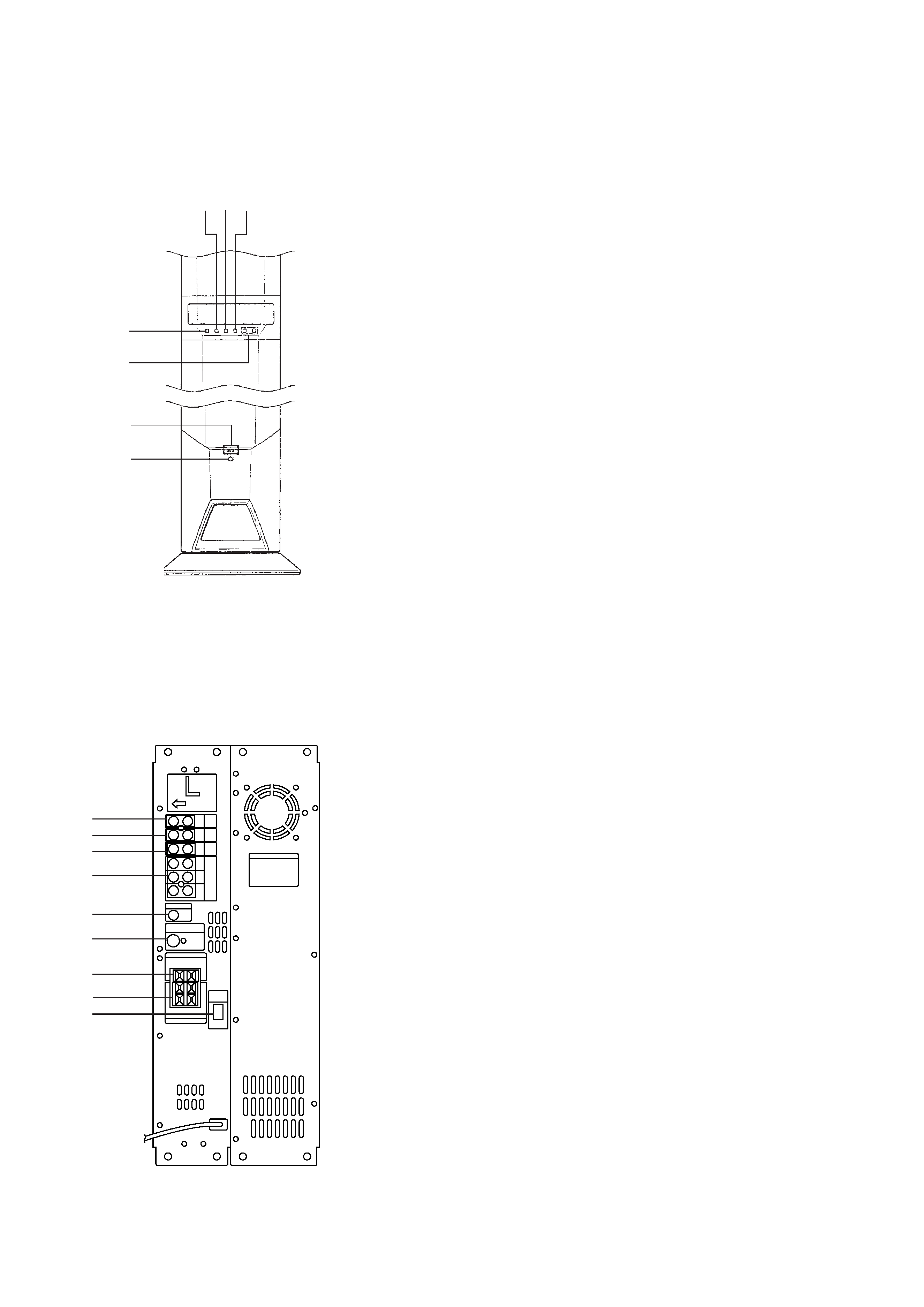
· LOCATION OF CONTROLS
Main Unit (L-ch)
Front View
1 INPUT button
2 SURROUND button
3 CENTER MODE button
4 S. WOOFER button
5 MASTER VOL +/ buttons
6 STANDBY, ON, READY indicators
7 U button
1 TV IN jack
2 VIDEO IN jack
3 AUX IN jack
4 5.1CH INPUT (FRONT, REAR, WOOFER, CENTER) jack
5 CONTROL S, TV IN jack (US, Canadian models)
6 WIRELESS REAR SPEAKER jack
7 CENTER SPEAKER terminal
8 REAR SPEAKERS terminal
9 R-ch SPEAKER OUTPUT connector
Rear View
2 3 4
1
5
6
7
1
2
3
4
5
6
7
8
9
5
AMPLIFIER SECTION
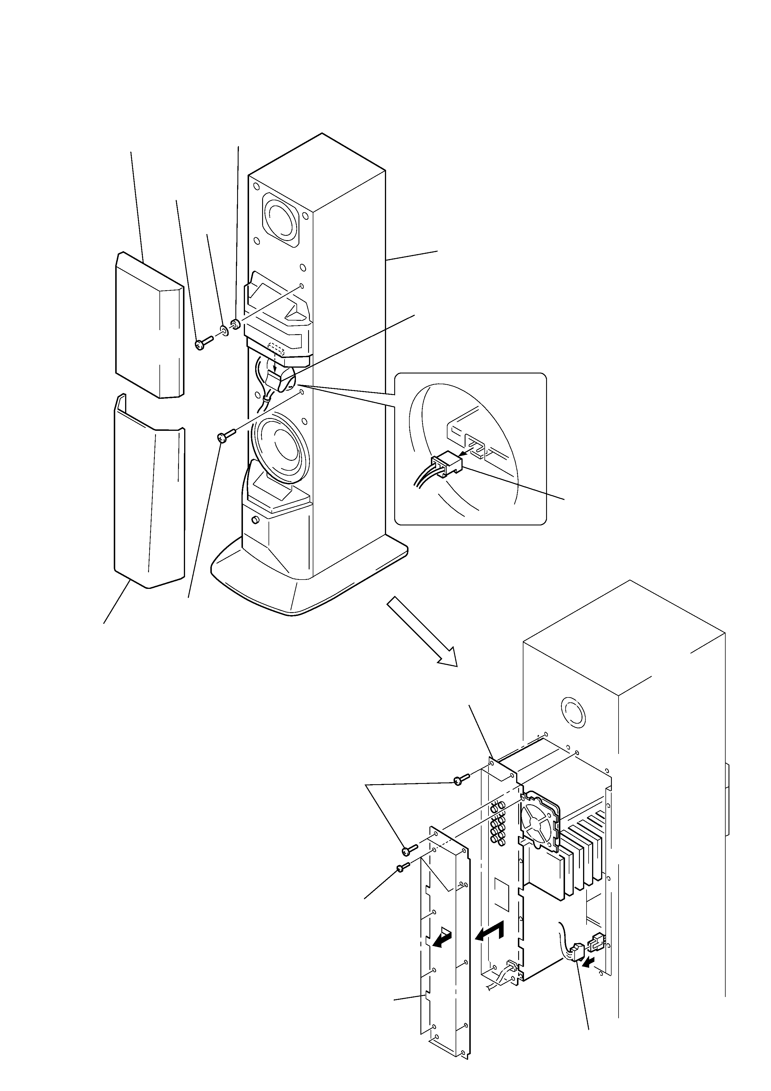
Note: Follow the disassembly procedure in the numerical order given.
SECTION 3
DISASSEMBLY
2 grille frame (A)
ass'y
3 screw
(BVTT4
× 25)
6 screw
(BVTT4
× 25)
4 washer
(BF)
5 washer
(S)
L-ch speaker section
7 flat wire
(CN503)
8 connector
(CN907)
1 grille frame (B) ass'y
!º five screws
(BVTP3
× 8)
!TM connector
!£ Remove the amplifier
section in arrow
B
direction.
!¡ Remove the panel (L/B)
in arrow
A direction.
9 eleven screws
(4
× 20)
B
A