MICROFILM
SERVICE MANUAL
FM STEREO/AM PLL
SYNTHESIZED RADIO
US Model
SPECIFICATIONS
SRF-PSY04
Photo: Blue model
Ver 1.0 1999. 06
2
TABLE OF CONTENTS
1.
GENERAL ................................................................... 3
2.
DISASSEMBLY ......................................................... 4
3.
ELECTRICAL ADJUSTMENTS ......................... 5
4.
DIAGRAMS
4-1. Block Diagram ................................................................
7
4-2. Printed Wiring Boards .....................................................
9
4-3. Schematic Diagram ......................................................... 11
4-4. IC Pin Function Description ........................................... 15
5.
EXPLODED VIEW ................................................... 16
6.
ELECTRICAL PARTS LIST ............................... 17
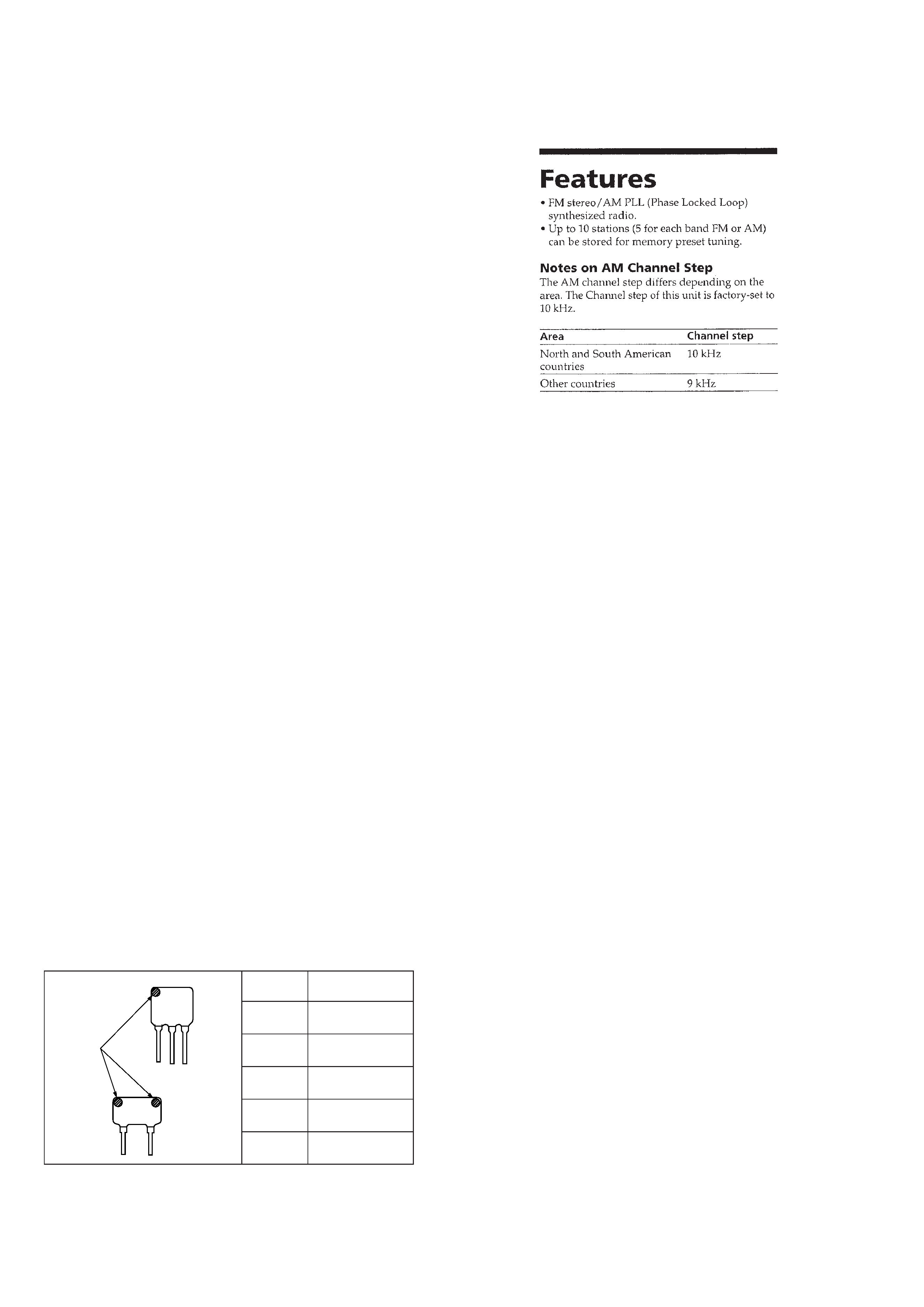
Notes on chip component replacement
· Never reuse a disconnected chip component.
· Notice that the minus side of a tantalum capacitor may be dam-
aged by heat.
CF3
CF1
mark
Mark
Center frequency
red
10.70 MHz
blue
10.67 MHz
orange
10.73 MHz
black
10.64 MHz
white
10.76 MHz
HOW TO CHANGED THE CERAMIC FILTERS
This model is used two ceramic filters of CF1 and CF3.
You must use same type of color marked ceramic filters in order to
meet same specifications.
Therefore, the ceramic filter must be changed two pieces together
since it's supply two pieces in one package as a spare parts.
3
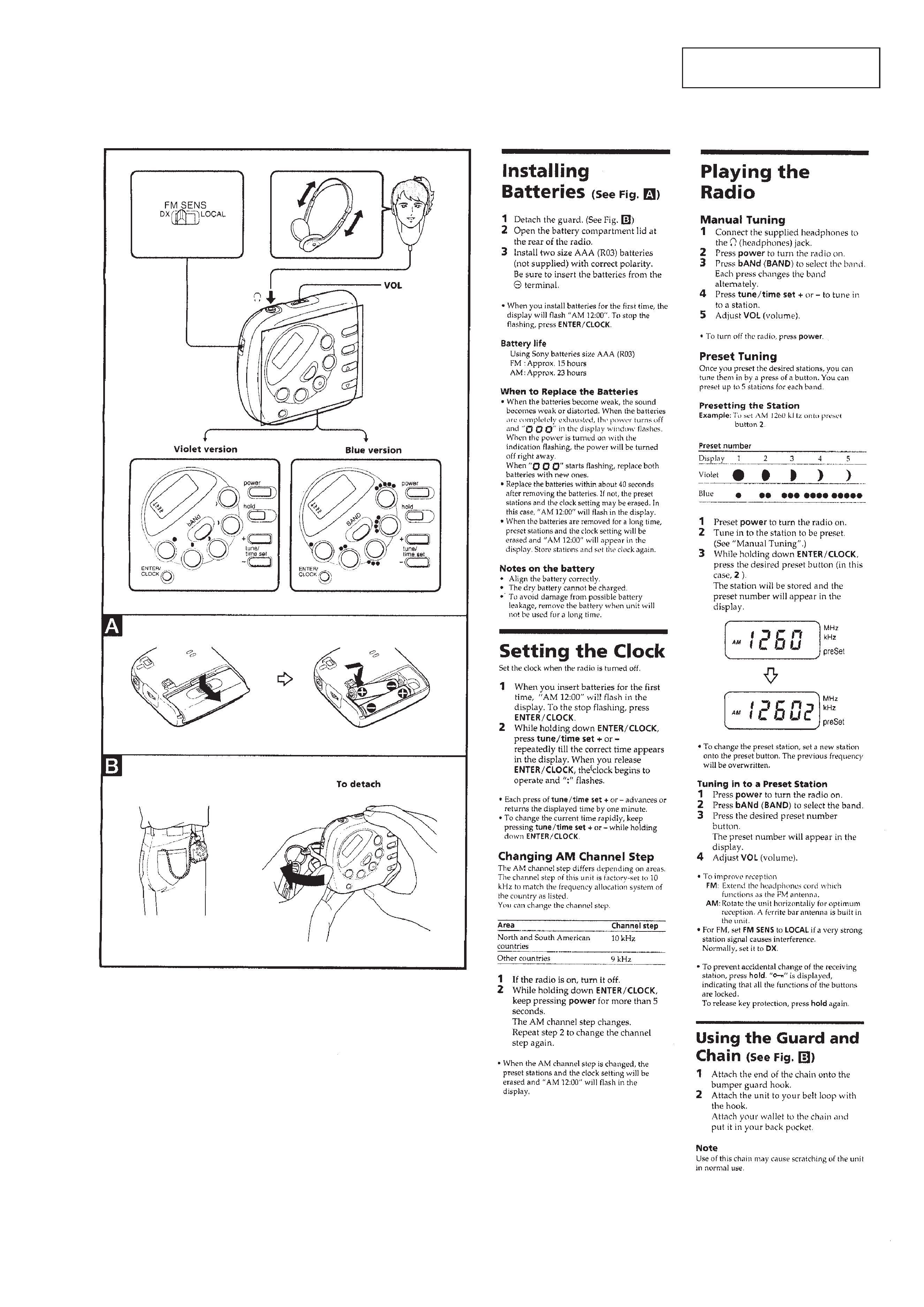
SECTION 1
GENERAL
This section is extracted from
instruction manual.
4
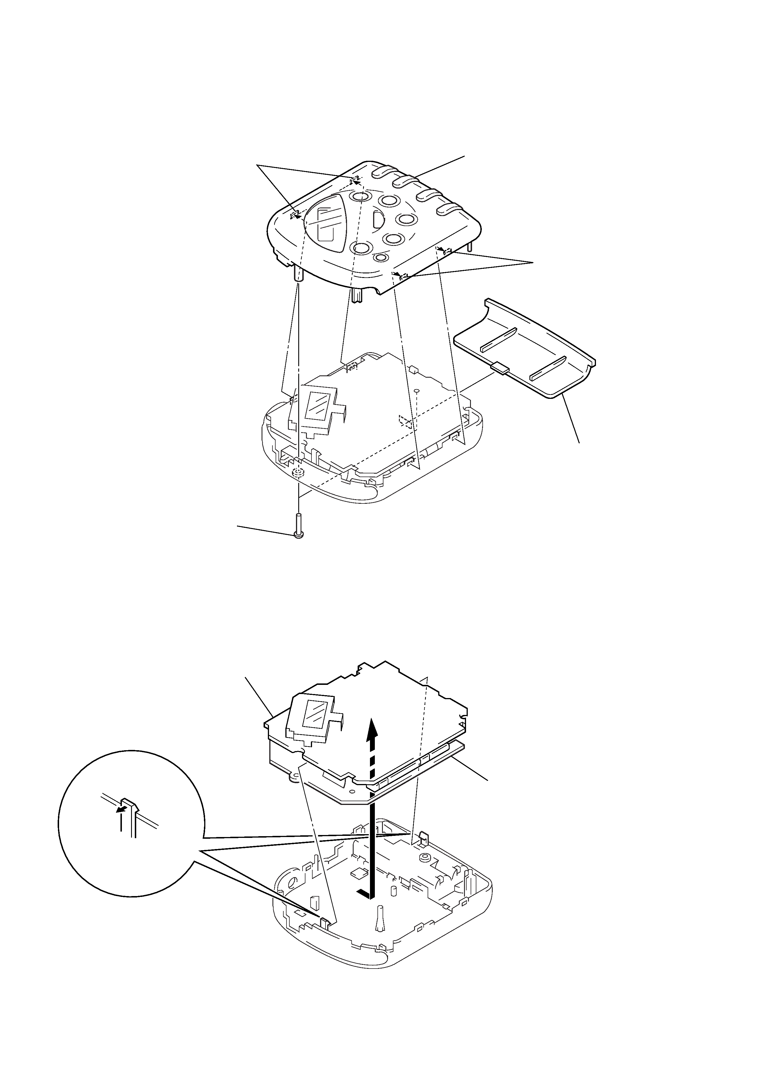
FRONT CABINET
MAIN BOARD, KEY BOARD
SECTION 2
DISASSEMBLY
Note: Follow the disassembly procedure in the numerical order given.
4 front cabinet
3 two claws
1 lid, battery case
2 two screws
(P2
× 8)
3 two claws
1 two claws
2 KEY board
2 MAIN board
5
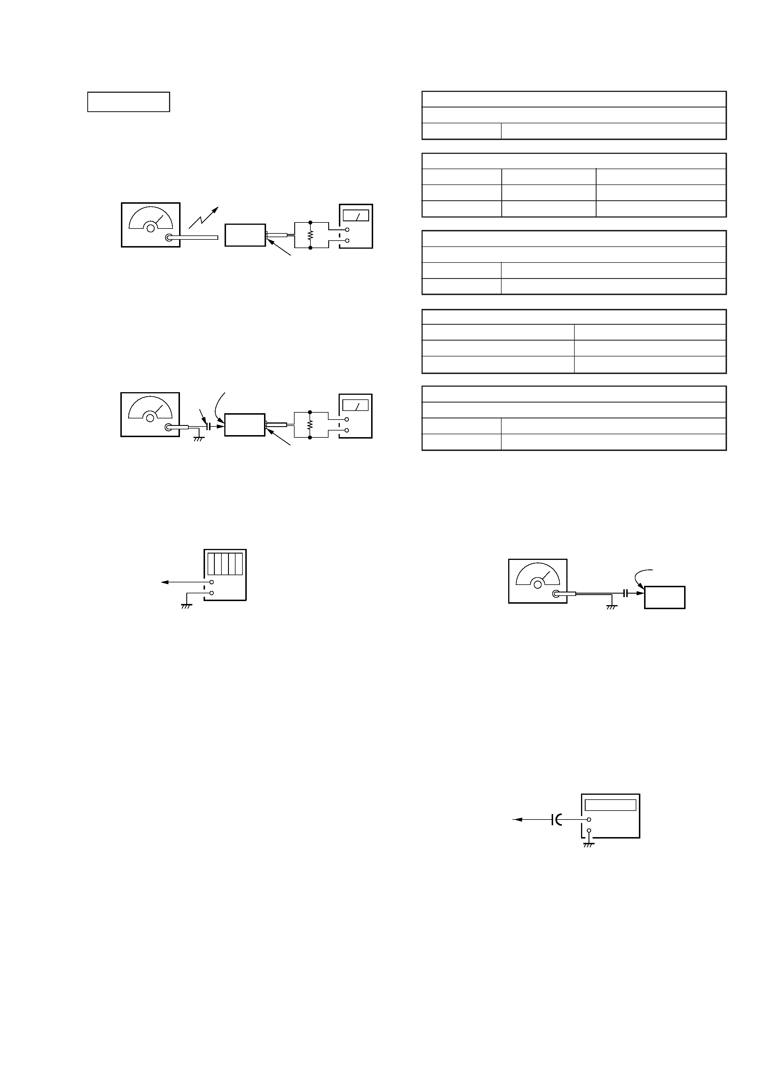
SECTION 3
ELECTRICAL ADJUSTMENTS
AM IF ADJUSTMENT
Adjust for a maximum reading on level meter
T1
450 kHz
AM FREQUENCY COVERAGE ADJUSTMENT
Adjustment Part
Frequency Display
Reading on Digital Voltmeter
L5
530 kHz
2.7 ± 0.1V
Confirmation
1,710 kHz
8.9 ± 1V
AM TRACKING ADJUSTMENT
Adjust for a maximum reading on level meter
L2
580 kHz
CT1
1,490 kHz
FM VCO VOLTAGE CONFIRMATION
Frequency Display
Reading on Digital Voltmeter
87.5 MHz
2.7 ± 0.1V
108 MHz
8.9 ± 1V
FM TRACKING ADJUSTMENT
Adjust for a maximum reading on level meter
L3
87.5 MHz
CT2
108 MHz
0 dB=1 µV
[AM]
Setting:
BAND switch: AM
[FM]
Setting:
BAND switch:
FM
FM SENS switch: DX
· Repeat the procedures in each adjustment several times, and the
tracking adjustments should be finally done by the trimmer ca-
pacitors.
Adjustment Location: Main Board (See page 6)
FM RF signal
generator
22.5 kHz frequency
deviation by 400 Hz
signal
Output level: as low as possible
+
level meter
2 (headphones) jack (J1)
set
MAIN board
TP (ANT)
16
0.01
µF
+
digital voltmeter
MAIN board
TP (VT)
FM STEREO (76 kHz) Adjustment
Setting:
BAND switch:
FM
FM SENS switch: DX
Procedure:
1. Connect the frequency counter to TP (76 kHz) as shown the
figure below.
2. Tune the set to 98 MHz.
3. Adjust RV1 for 76 kHz reading on the frequency counter.
Specification: 75.5 to 76.5 kHz
Adjustment Location: MAIN board (See page 6)
0.01
µF
MAIN board
TP (ANT)
set
FM RF signal
generator
Carrier frequency : 98 MHz
Modulation
: 1 kHz, 22.5 kHz deviation
Output level
: 562
µV (55 dB)
+
MAIN board
TP (76 kHz)
+
1
µF
frequency
counter
AM RF signal
generator
30% amplitude
modulation by
400 Hz signal
Output level: as low as possible
Put the lead-wire
antenna close to
the set.
+
level meter
set
16
2 (headphones) jack (J1)