SERVICE MANUAL
Sony Corporation
Personal Audio Group
Published by Sony Engineering Corporation
SRF-MQ11
US Model
AEP Model
UK Model
E Model
Australian Model
FM STEREO PLL
SYNTHESIZED HEADPHONE RADIO
SPECIFICATIONS
Ver. 1.2 2005.03
9-877-505-03
2005C16-1
© 2005.03
Radio segment
Model for North and South America
Frequency range: FM 87.5-108 MHz
Channel step: 0.1 MHz
Model for other countries/regions
Frequency range: FM 87.5-108 MHz
Channel step: 0.05 MHz
Power output: 3.0 mW + 3.0 mW (at 10% harmonic distortion)
Headphone segment
Headphone type: Open-air Dynamic
Driver unit: ø 30 mm Dome type
Input: ø 3.5 mm stereo mini-jack
Power handling capacity: 1 000 mW (IEC)
Impedance: 24
(at 1 kHz)
Frequency response: 20 to 24 000 Hz
Others
Power requirements
1.2 V DC, Built-in nickel metal hydride battery
4.5 V DC, Charge in the AC power adaptor
Mass
Approx. 75 g (2.65 oz)
Accessories supplied
Connecting cord (1), AC power adaptor (1)
Design and specifications are subject to change without notice.
2
SRF-MQ11
Notes on chip component replacement
·Never reuse a disconnected chip component.
· Notice that the minus side of a tantalum capacitor may be dam-
aged by heat.
Unleaded solder
Boards requiring use of unleaded solder are printed with the lead-
free mark (LF) indicating the solder contains no lead.
(Caution: Some printed circuit boards may not come printed with
the lead free mark due to their particular size.)
: LEAD FREE MARK
Unleaded solder has the following characteristics.
· Unleaded solder melts at a temperature about 40°C higher than
ordinary solder.
Ordinary soldering irons can be used but the iron tip has to be
applied to the solder joint for a slightly longer time.
Soldering irons using a temperature regulator should be set to
about 350°C.
Caution: The printed pattern (copper foil) may peel away if the
heated tip is applied for too long, so be careful!
· Strong viscosity
Unleaded solder is more viscous (sticky, less prone to flow) than
ordinary solder so use caution not to let solder bridges occur such
as on IC pins, etc.
· Usable with ordinary solder
It is best to use only unleaded solder but unleaded solder may
also be added to ordinary solder.
SAFETY-RELATED COMPONENT WARNING!!
COMPONENTS IDENTIFIED BY MARK 0 OR DOTTED LINE WITH
MARK 0 ON THE SCHEMATIC DIAGRAMS AND IN THE PARTS
LIST ARE CRITICAL TO SAFE OPERATION. REPLACE THESE
COMPONENTS WITH SONY PARTS WHOSE PART NUMBERS
APPEAR AS SHOWN IN THIS MANUAL OR IN SUPPLEMENTS
PUBLISHED BY SONY.
TABLE OF CONTENTS
1. GENERAL ·········································································· 3
2. DISASSEMBLY
2-1. Cabinet (Rear) Assy (R) ·················································· 4
2-2. MAIN Board ··································································· 5
2-3. MICROCOMPUTER Board ··········································· 5
2-4. Hanger (R) Section ························································· 6
2-5. Speaker (R) ····································································· 7
2-6. Cabinet (Rear) Assy (L) ·················································· 7
2-7. Hanger (L) Section ·························································· 8
2-8. BATTERY Board ···························································· 9
2-9. Speaker (L) ····································································· 9
3. ADJUSTMENTS ···························································· 10
4. DIAGRAMS
4-1. Block Diagram ······························································ 12
4-2. Printed Wiring Board MAIN Board ······················· 13
4-3. Schematic Diagram MAIN Board ························· 14
4-4. Printed Wiring Board
MICROCOMPUTER Board ·································· 15
4-5. Schematic Diagram
MICROCOMPUTER Board ·································· 16
4-6. Printed Wiring Board BATTERY Board ················ 17
4-7. Schematic Diagram BATTERY Board ·················· 18
4-8. IC Pin Function Description ········································· 20
5. EXPLODED VIEWS ······················································ 21
6. ELECTRICAL PARTS LIST ······································· 22
· Use the Sony AC power adaptor (supplied) only. The polarity of the plugs of
other manufacturers may be different. Failure to use the recommended AC
power adaptor may cause the unit to malfunction.
Polarity of the plug
For the customers in the U.S.A.
RECYCLING NICKEL METAL HYDRIDE BATTERIES
Nickel Metal Hydride batteries are
recyclable.
You can help preserve our environment by returning
your used rechargeable batteries to the collection
and recycling location nearest you.
For more information regarding recycling of
rechargeable batteries, call toll free
1-800-822-8837, or visit http://www.rbrc.org/
Caution: Do not handle damaged or leaking
Nickel Metal Hydride batteries.
3
SRF-MQ11
SECTION 1
GENERAL
This section is extracted
from instruction manual.
When Disposing of the Radio
This radio has a built-in Nickel Metal Hydride battery. When you recycle the
battery, remove it following the procedure below.
Certain countries/regions may regulate disposal of the battery
used to power this product.
Please consult with your local authority.
Note
Never disassemble this radio excepts when disposing of it.
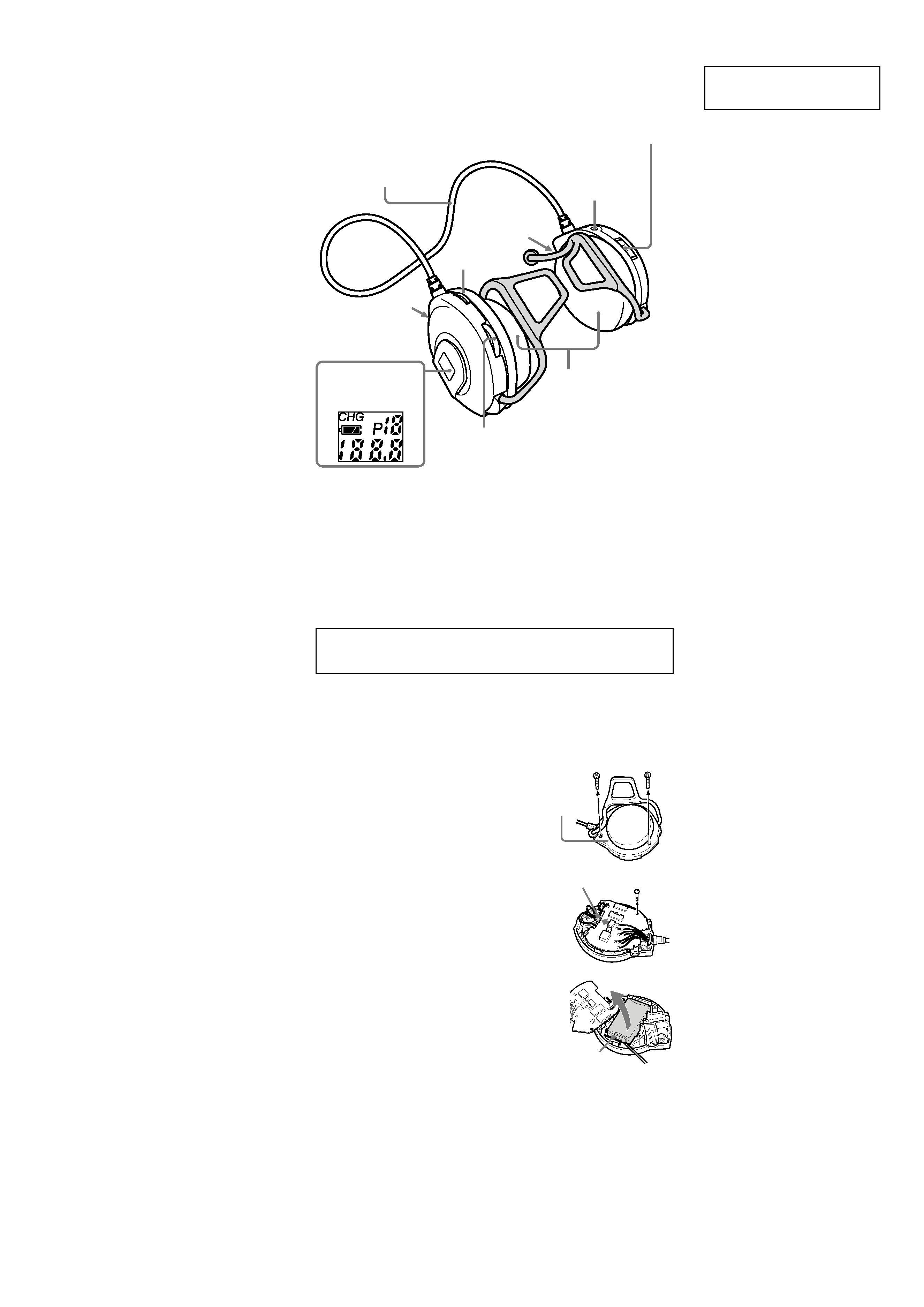
To remove the Nickel Metal Hydride battery
The Nickel Metal Hydride battery is stored in the left unit.
1 Remove both screws on the left cabinet (as
shown in the illustration) using a Phillips
screw driver.
2 Remove the cabinet.
3 Dettach the connector shown by the arrow in
the illustration and then remove the screw on
the circuit board.
4 Raise the circuit board and remove the Nickel
Metal Hydride battery using a thin object, as
the battery is secured with tape.
L (left)
Nickel Metal Hydride battery
C
onnector
Cabinet
OFF·ON/
MEGABASS
Jog Lever (MODE/ENTER)
Molette (MODE/ENTER)
Display
Afficheur
VOL*
SENS DX/LOCAL
AUDIO IN
L (left)
L (gauche)
Cord
Cordon
Driver unit
Oreillettes
DC IN 4.5 V
R (right)
R (droite)
* There is a tactile dot beside volume to show the
direction to turn up the volume.
Un point tactile, situé à côté de la molette de
volume, indique le sens dans lequel il faut tourner
pour augmenter le volume.
4
SRF-MQ11
SECTION 2
DISASSEMBLY
Note :
Follow the disassembly procedure in the numerical order given.
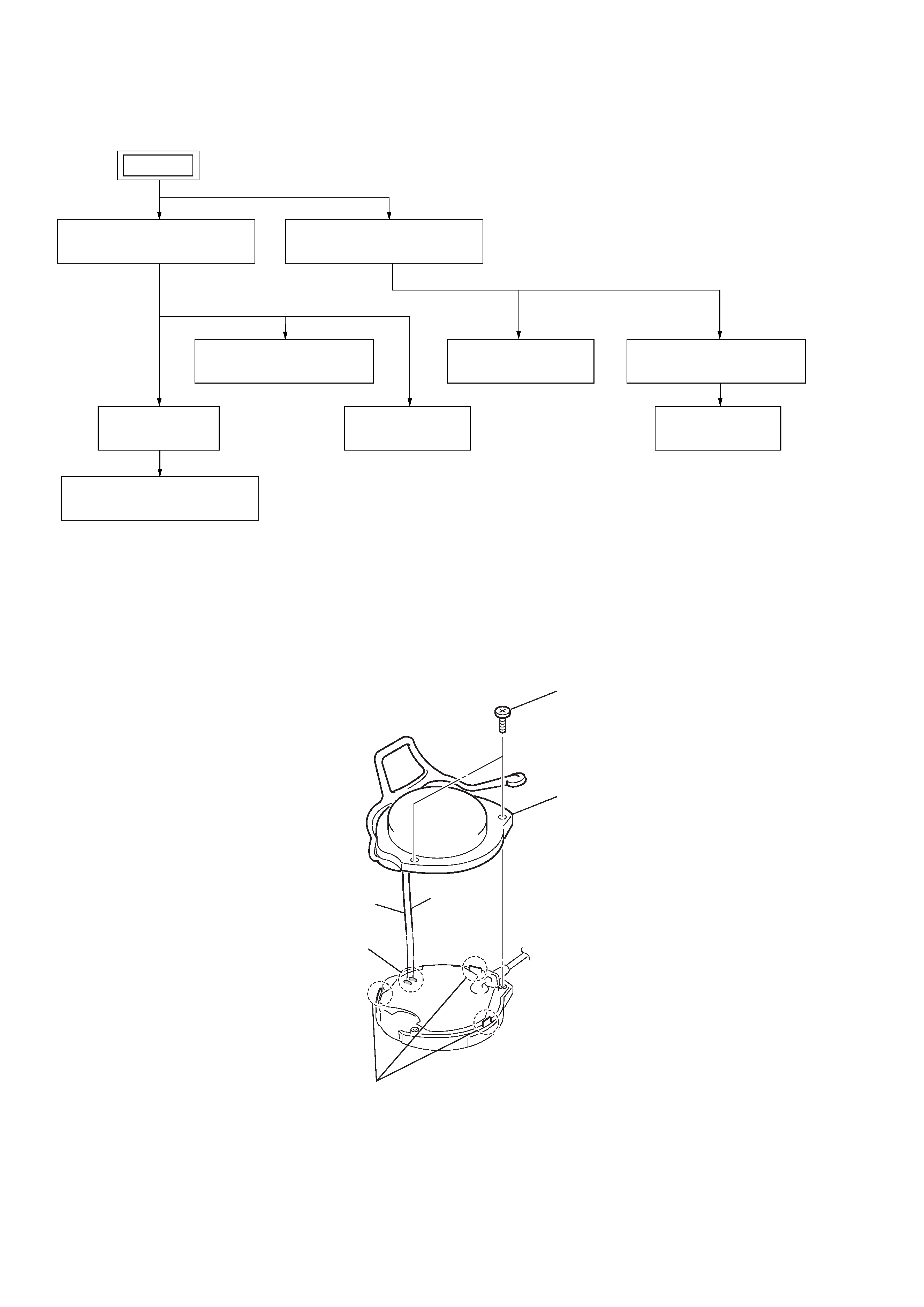
2-1. CABINET (REAR) ASSY (R)
· This set can be disassembled in the order shown below.
SET
2-1.CABINET (REAR) ASSY (R)
(Page 4)
2-3.MICROCOMPUTER BOARD
(Page 4)
2-2.MAIN BOARD
(Page 5)
2-4.HANGER (R) SECTION
(Page 6)
2-7.HANGER (L) SECTION
(Page 8)
2-5.SPEAKER (R)
(Page 7)
2-9.SPEAKER (L)
(Page 9)
2-8.BATTERY BOARD
(Page 9)
2-6.CABINET (REAR) ASSY (L)
(Page 7)
2
three claws
1
two screws
(1.4
× 6)
3
Remove soldering from the two points.
red
gray
4
cabinet (rear) assy (R)

5
SRF-MQ11
2-3. MICROCOMPUTER BOARD
2-2. MAIN BOARD
1
connector
3
lead wire (11core)
4
MAIN board
2
Remove soldering from the eleven points.
red (BATT)
purple (CHG)
orange (P-SW)
green (DCIN)
gray (R-CH)
brown (SP+)
natural (ANT)
yellow (COM)
blue (MB)
brack (L-CH)
white (GND)
2
MICROCOMPUTER board
1
screw
(B1.4
× 4)