SERVICE MANUAL
FM STEREO/AM PLL SYNTHESIZED RADIO
US Model
AEP Model
E Model
Australian Model
Chinese Model
Tourist Model
SPECIFICATIONS
SRF-M97
Ver. 1.2 2005.02
9-879-289-03
2005B05-1
© 2005.02
Sony Corporation
Personal Audio Company
Published by Sony Engineering Corporation
Tourist model
Band
Frequency range
Channel step
FM
76 - 108 MHz
0.05 MHz
AM
531 - 1 710 kHz
9 kHz
530 - 1 710 kHz
10 kHz
Sony
* The supplied battery is for trial. We recommend you to
purchase a Sony alkaline LR03 (size AAA) battery.
R03 (size AAA) battery (1) (for trial*) (Tourist model)
Time display:
North and South American
12-hour system
countries/regions
Other countries/regions
24-hour system
Frequency range:
Model for North and South America
countries/regions
Band
Frequency range
Channel step
FM
87.5 - 108 MHz
0.1 MHz
AM
530 - 1 710 kHz
10 kHz
531 - 1 710 kHz
9 kHz
Model for Other countries/regions
Band
Frequency range
Channel step
FM
87.5 - 108 MHz
0.05 MHz
AM
531 - 1 602 kHz
9 kHz
530 - 1 610 kHz
10 kHz
Output:
i (headphones) jack
(ø3.5 mm, stereo minijack)
Power output:
2 mW + 2 mW (at 10 % harmonic distortion)
Power requirements:
1.5 V DC, one R03 (size AAA) battery
Auto Power off function:
Approx. 30 minutes, 60 minutes, 90minutes, 120
minutes, and off
Dimensions:
Approx. 37.4
× 84.6 × 21.6 mm (w/h/d)
(Approx. 1 1/
2 × 3
3/
8 ×
7/
8 inches)
incl. projecting parts and controls
Mass:
Approx. 58.5 g (2.06 oz.)
incl. battery and the headphones
Accessories supplied
Stereo headphones (1)
Design and specifications are subject to change
without notice.
Battery Life (Approx. hours)
(JEITA*)
When using
FM
AM
Sony alkaline LR03
40
65
(size AAA)
Sony R03
16
30
(size AAA)
* Measured by JEITA (Japan Electronics and
Information Technology Industries Association)
standards. The actual battery life may vary
depending on the circumstance of the unit.

2
SRF-M97
TABLE OF CONTENTS
1.
GENERAL ................................................................... 3
2.
DISASSEMBLY
2-1.
Disassembly Flow ...........................................................
4
2-2.
MAIN Board, Cabinet (Front) Assy ................................
4
2-3.
Side Panel Section, Cabinet (Rear) Assy .........................
5
2-4.
AMP Board ......................................................................
5
3.
ELECTRICAL ADJUSTMENTS ......................... 6
4.
DIAGRAMS ................................................................. 8
4-1.
Schematic Diagram .........................................................
9
4-2.
Printed Wiring Board MAIN Board .......................... 10
4-3.
Printed Wiring Board AMP Board ............................ 11
5.
EXPLODED VIEWS
5-1.
Cabinet (Front) Section ................................................... 14
5-2.
Cabinet (Rear) Section .................................................... 15
6.
ELECTRICAL PARTS LIST ................................ 16
Notes on chip component replacement
· Never reuse a disconnected chip component.
· Notice that the minus side of a tantalum capacitor may be
damaged by heat.
Flexible Circuit Board Repairing
· Keep the temperature of the soldering iron around 270 °C
during repairing.
· Do not touch the soldering iron on the same conductor of the
circuit board (within 3 times).
· Be careful not to apply force on the conductor when soldering
or unsoldering.
UNLEADED SOLDER
Boards requiring use of unleaded solder are printed with the lead-
free mark (LF) indicating the solder contains no lead.
(Caution: Some printed circuit boards may not come printed with
the lead free mark due to their particular size)
: LEAD FREE MARK
Unleaded solder has the following characteristics.
· Unleaded solder melts at a temperature about 40 °C higher
than ordinary solder.
Ordinary soldering irons can be used but the iron tip has to be
applied to the solder joint for a slightly longer time.
Soldering irons using a temperature regulator should be set to
about 350
°C.
Caution: The printed pattern (copper foil) may peel away if
the heated tip is applied for too long, so be careful!
· Strong viscosity
Unleaded solder is more viscou-s (sticky, less prone to flow)
than ordinary solder so use caution not to let solder bridges
occur such as on IC pins, etc.
· Usable with ordinary solder
It is best to use only unleaded solder but unleaded solder may
also be added to ordinary solder.
3
SRF-M97
SECTION 1
GENERAL
This section is extracted from
instruction manual.
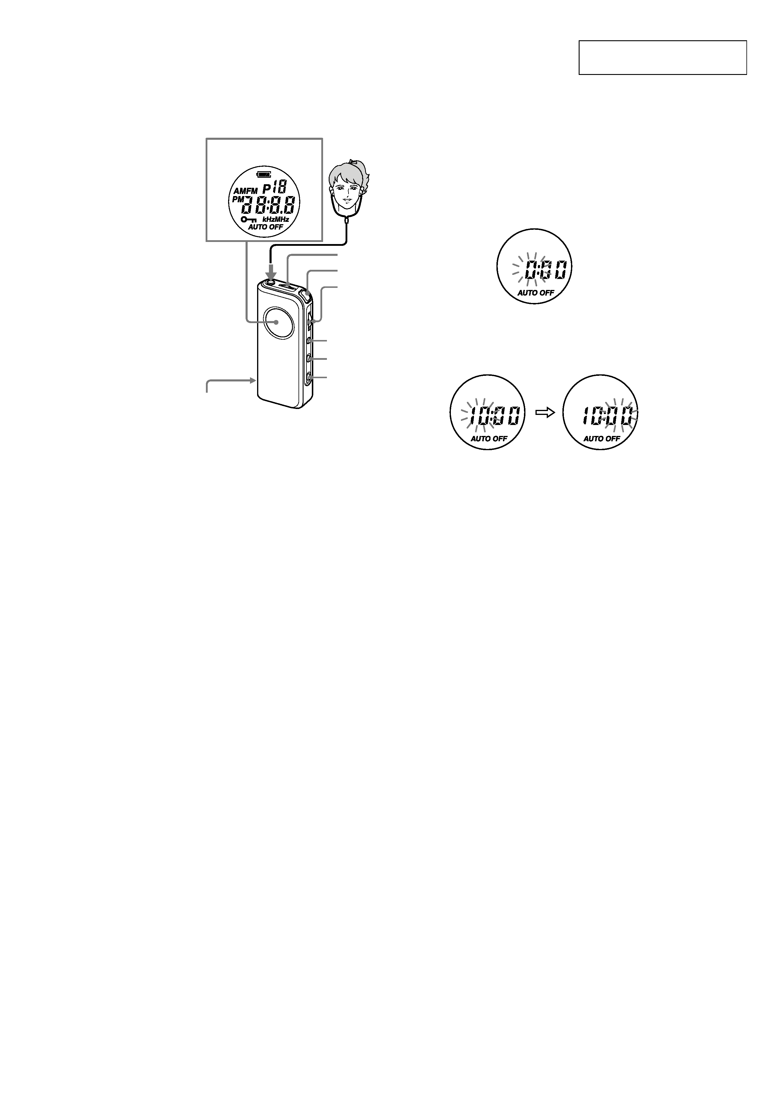
Front
Parte frontal
FM SENS
DX/LOCAL
(Except Tourist model)
STEREO/MONO
(Tourist model)
FM
POWER
Jog Lever
(ENT/BAND)
Sintonizador
(ENT/BAND)
MODE
HOLD
Display Window
Ventana del visualizador
VOL*
MEGABASS
i
* There is a tactile dot beside VOL to show
the direction to turn up the volume.
* Al lado de la tecla VOL hay un punto táctil
que muestra el sentido para subir el
volumen.
Setting the Clock
The clock system varies depending on the model you
own.
12-hour system: "AM 12:00" = midnight
24-hour system: "0:00" = midnight
The time display of this clock is a 24-hour system.
1 Press POWER to turn off the power.
2 Press and hold down the jog lever for more
than 2 seconds until "the hour" starts
flashing.
3 Slide or keep sliding the jog lever up or
down to adjust the hour and press the jog
lever.
If you keep sliding the jog lever up or down, the
number changes rapidly.
4 Slide the jog lever up or down to adjust the
minutes and press the jog lever.
":" starts flashing and the clock starts
operating.
To set the current time exactly to the second,
adjust the minute and then press the jog lever in
time with a time signal (such as a radio station).
To cancel the setting, press MODE.
Note
Once you start setting the clock, you must perform
each step within about 65 seconds, or the clock setting
mode will be cancelled.
SRF-M97
4
Note: Follow the disassembly procedure in the numerical order given.
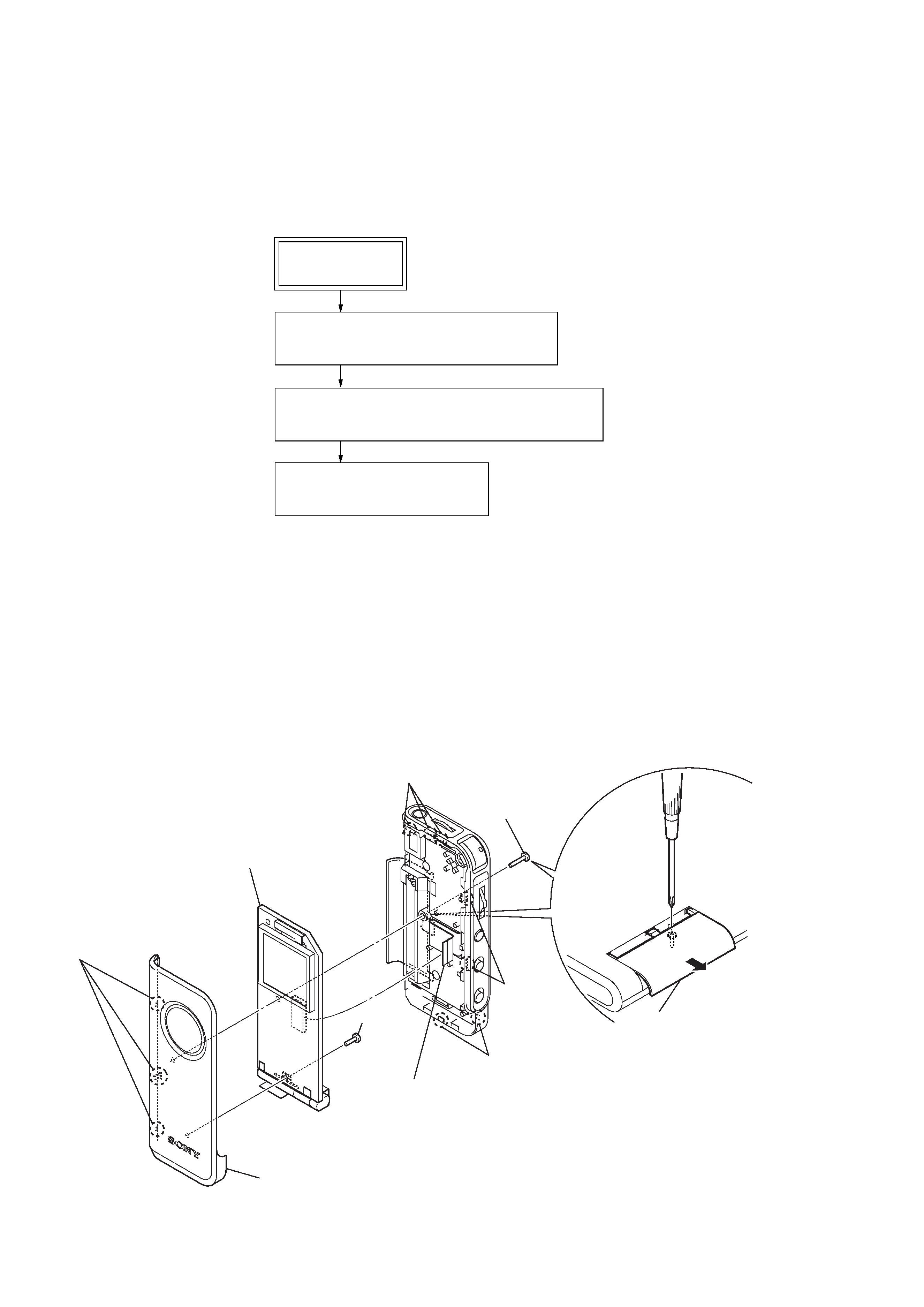
2-2. MAIN BOARD, CABINET (FRONT) ASSY
· This set can be disassembled in the order shown below.
2-1. DISASSEMBLY FLOW
SECTION 2
DISASSEMBLY
SET
2-2. MAIN BOARD, CABINET (FRONT) ASSY
(Page 4)
2-4. AMP BOARD
(Page 5)
2-3. SIDE PANEL SECTION, CABINET (REAR) ASSY
(Page 5)
2
screw (1.4)
5
screw
(B1.4)
6
MAIN board
4
connection flexible borad
(CN1)
3
three claws
3
three claws
7
cabinet (front) assy
3
two claws
3
two claws
1
Open the battery lid.
SRF-M97
5
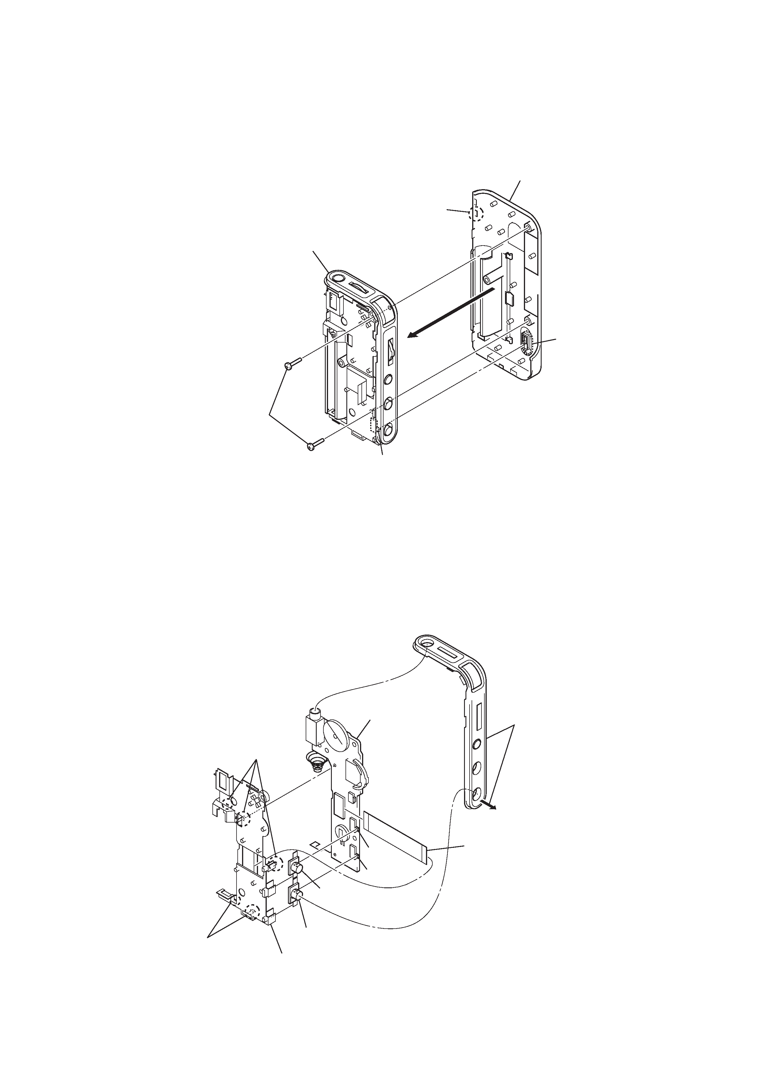
2-3. SIDE PANEL SECTION, CABINET (REAR) ASSY
2-4. AMP BOARD
S205
S204
Note : On installation of AMP board,
adjust the position of switch
(S204, S205) and knob (hold, mega bass).
4
connection flexible board
(CN201)
5
knob (mega bass)
6
knob (hold)
7
holder (jack)
1
Please open a side panel
forcibly and do not remove it.
2
two claws
2
three claws
3
AMP board
S203
1
two screws (1.4)
2
claw
4
cabinet (rear) assy
3
side panel section
Note : On installation of side panel section
and cabinet (rear) assy,
adjust the position of switch
(S203) and knob (rear).
knob (rear)