Ver 1.0 1999.09
MICROFILM
SRF-M55
SERVICE MANUAL
FM STEREO PLL SYNTHESIZED RADIO
SPECIFICATIONS
AEP Model
E Model
Chinese Model
2
Specifications ........................................................................... 1
1. GENERAL
Location and Function of Controls .................................... 2
2. DISASSEMBLY
2-1. "Cabinet ASSY, Front", "Cabinet ASSY, Rear" ......... 3
2-2. Main Board ................................................................. 3
2-3. LCD201 ...................................................................... 4
2-4. Microcomputer Board ................................................. 4
3. ADJUSTMENTS .......................................................... 5
4. DIAGRAMS
4-1. Explanation of IC Terminals ....................................... 6
4-2. Block Diagrams .......................................................... 7
4-3. Printed Wiring Boards .............................................. 10
4-4. Schematic Diagram ................................................... 13
5. EXPLODED VIEW ..................................................... 17
6. ELECTRICAL PARTS LIST .................................... 18
Flexible Circuit Board Repairing
· Keep the temperature of the soldering iron around 270°C during
repairing.
· Do not touch the soldering iron on the same conductor of the
circuit board (within 3 times).
· Be careful not to apply force on the conductor when soldering or
unsoldering.
Notes on chip component replacement
· Never reuse a disconnected chip component.
· Notice that the minus side of a tantalum capacitor may be dam-
aged by heat.
TABLE OF CONTENTS
SECTION 1
GENERAL
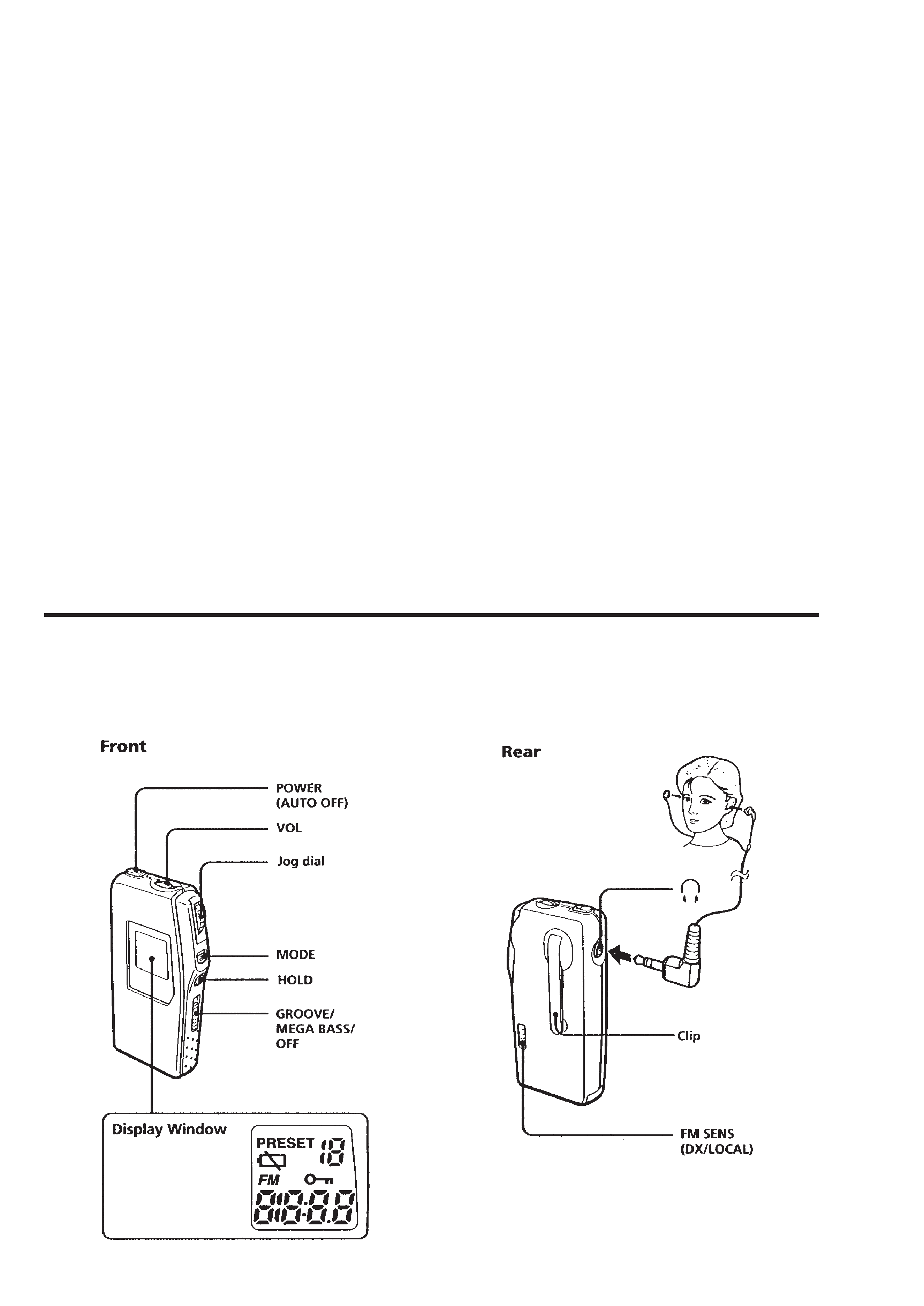
LOCATION AND FUNCTION OF CONTROLS
3
SECTION 2
DISASSEMBLY
Note : Follow the disassembly procedure in the numerical order given.
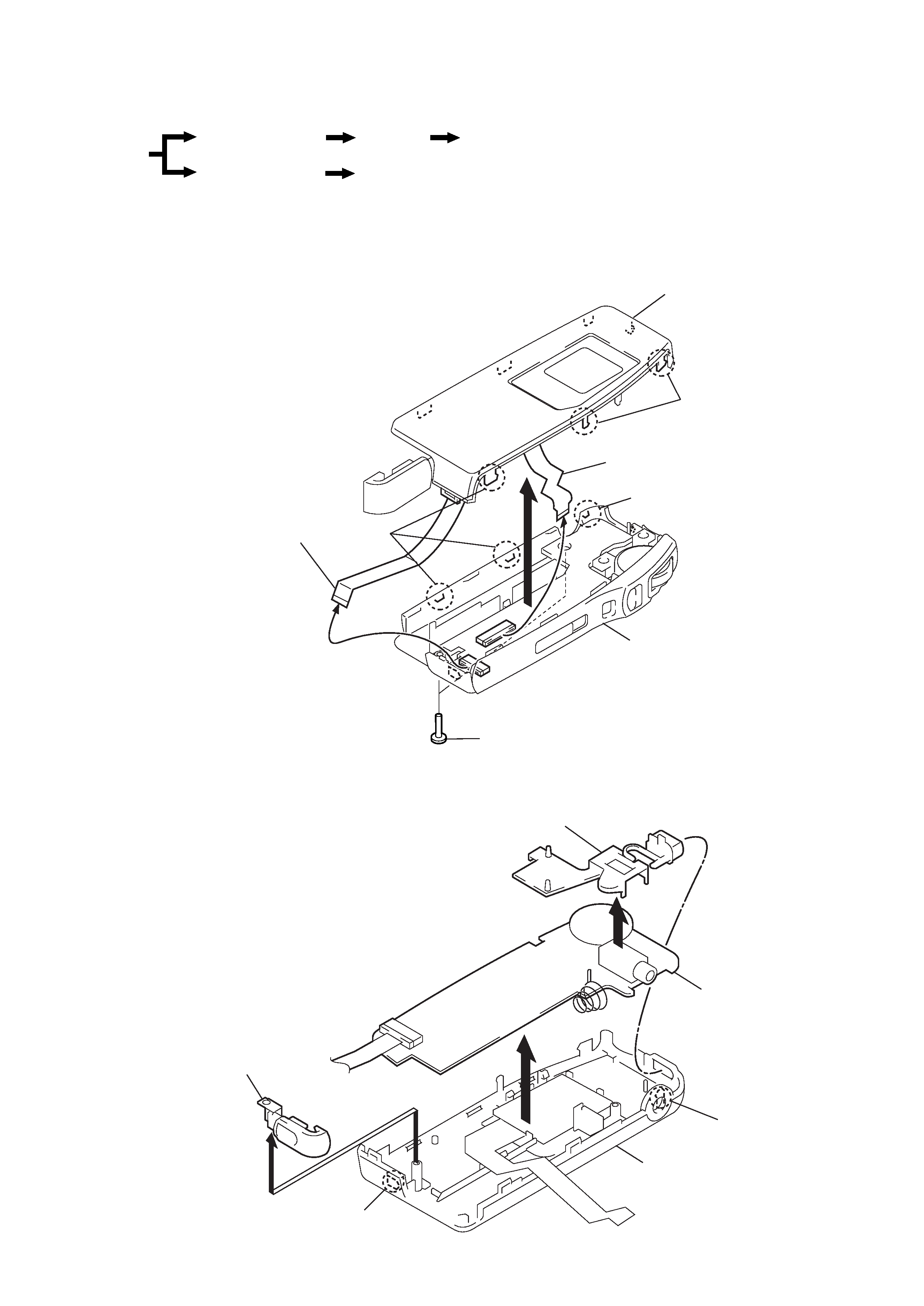
2-1. "CABINET ASSY, FRONT", "CABINET ASSY, REAR"
2-2. MAIN BOARD
r
The equipment can be removed using the following procedure.
Cabinet ASSY, Front
Cabinet ASSY, Rear
Set
Main board
Microcomputer board
LCD201
1
Screws (B1.7x8)
2
Claws
2
Claws
3
4
Flexible board
(10 core)
5
LCD flexible board (13 core)
Cabinet ASSY, rear
Cabinet ASSY, front
2
Claw
3
Claw
4
1
2
Main board
Cabinet ASSY, front
Button (power)
Lid, battery case
3
Claw
4
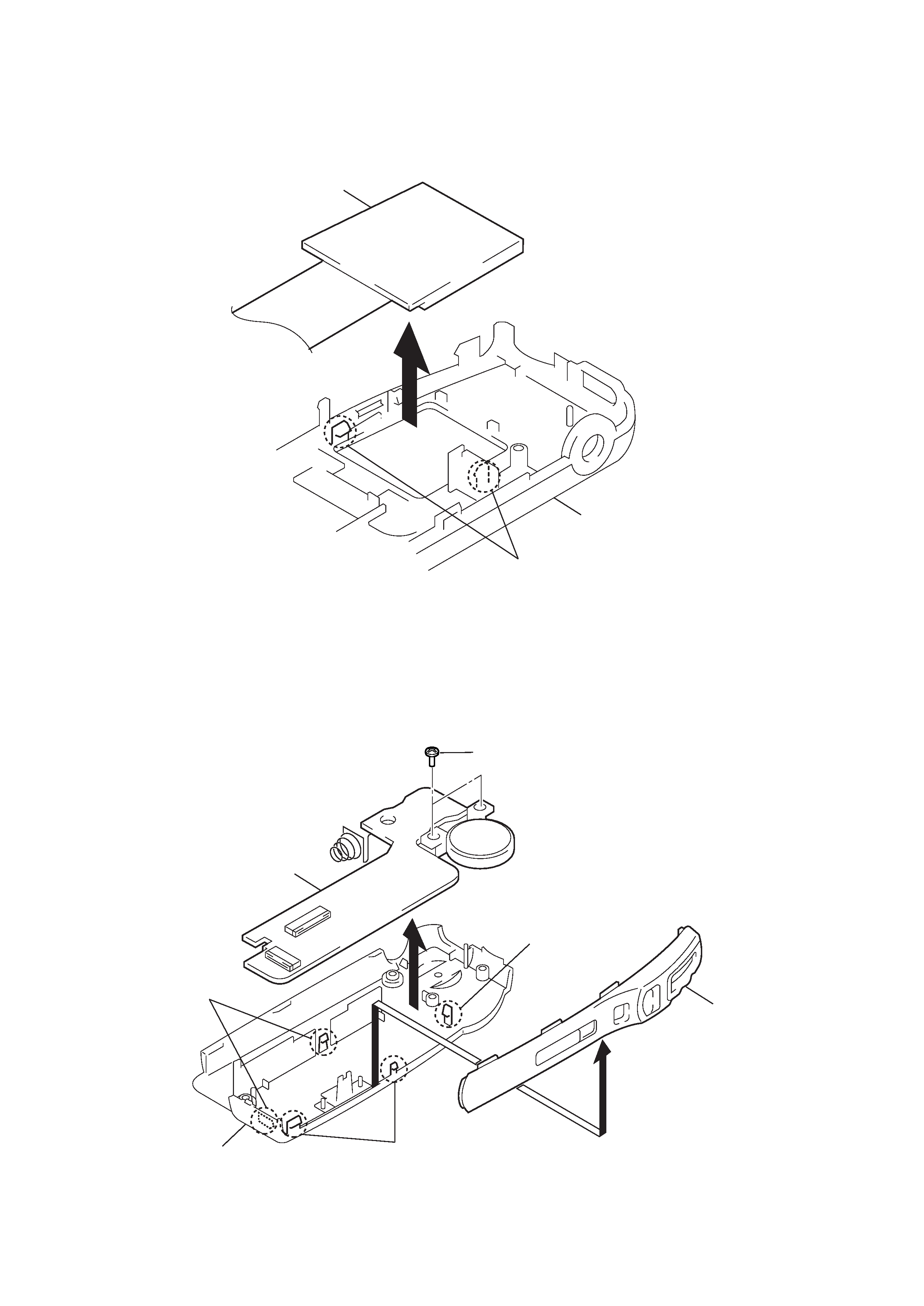
2-3. LCD201
2-4. MICROCOMPUTER BOARD
1
Claws
2
Cabinet ASSY, front
LCD201
1
Screws (1.4)
3
5
Cabinet ASSY, rear
4
Claw
4
Claws
2
Claws
Microcomputer board
Cover, side
5
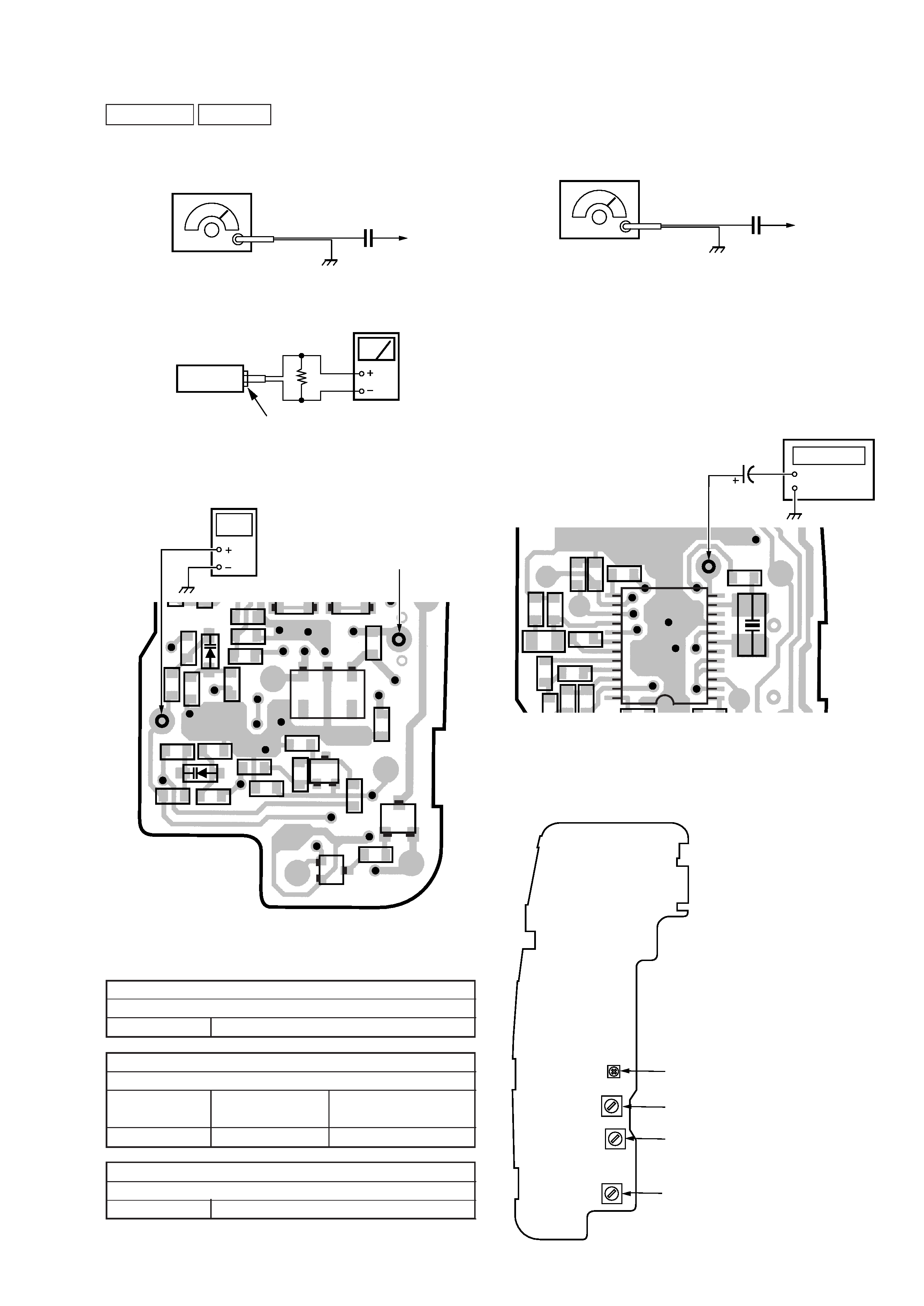
FM STEREO (19kHz) Adjustment
Setting :
Procedure :
1. Connect the frequency counter to TP (19kHz).
2. Turn the set to 98MHz.
3. Adjust RV1 for 19kHz reading frequency counter.
Standard Value : 18.9 19.1kHz
Connection:
SECTION 3
ADJUSTMENTS
FM Section
Setting :
Connection:
For FM frequency coverage adjustment
·
Repeat the procedures in each adjustment several times, and the
frequency coverage and tracking adjustments should be finally
done by the trimmer capacitors.
FM IF ADJUSTMENT
Adjust for a maximum reading on level meter.
T1
10.7MHz
FM FREQUENCY COVERAGE ADJUSTMENT
Adjust for a maximum reading on level meter.
CT2
87.5MHz
adjustment value: 2V
standard value: 1.5 2.5V
Confirm
108.0MHz
standard value: 9 13V
FM TRACKING ADJUSTMENT
Adjust for a maximum reading on level meter.
CT1
98MHz
FM RF signal
generator
22.5kHz frequency deviation by
400Hz signal.
Output level : as low as possible
TP (ANT)
0.01
µF
set
16
headphones jack EP1 (i)
level meter
FM RF signal
generator
Carrier frequency : 98MHz
Modulation : 1kHz, 22.5kHz deviation
Output level : 1mV (more than 60dB)
TP (ANT)
0.01
µF
1-676-002-
C
C101
C102
R106
R105
R109
R119
R120
R111
R107
R102
R108
R101
R104
R103
R
C103
C124
C105
C104
C125
Q
CF1
BPF101
CF2
D101
D102
BE
C
BCE
Q104
Q101
Q105
ECB
TP
(ANT)
TP
(LPF)
digital
voltmeter
TP
(ANT)
[MAIN BOARD]
(SIDE A)
TP (LPF)
1
5
13
15
20
24
10
12
IC101
C114
C115
C113
C
109
C
108
R121
R115
1
12
R113
R114
C111
C110
C107
C116
C112
CF3
TP
(19kHz)
frequency counter
TP (19kHz)
1
µF/50V
[MAIN BOARD] (SIDE A)
0 dB=1
µV
Adjustments Location :
CT2 : FM Frequency Coverage
Adjustment
CT1 : FM Tracking Adjustment
T1 : FM IF Adjustment
RV1 : FM Stereo (19kHz) Adjustment
[MAIN BOARD] (SIDE A)