MICROFILM
SERVICE MANUAL
SPECIFICATIONS
CD RADIO CASSETTE-CORDER
E Model
Model Name Using Similar Mechanism
NEW
CD Mechanism Type
KSM-213CDM
Optical Pick-up Name
KSS-213C
Model Name Using Similar Mechanism
NEW
Tape Transport Mechanism Type
MF-CD777
CFD-CD777S
CD
Section
TAPE
Section
Ver 1.0 1998. 06

2
TABLE OF CONTENTS
1.
SERVICING NOTES ................................................ 3
2.
GENERAL ................................................................... 4
3.
DISASSEMBLY ......................................................... 8
4.
MECHANICAL ADJUSTMENTS ....................... 12
5.
ELECTRICAL ADJUSTMENTS
Tape Deck Section .......................................................... 12
Tuner Section .................................................................. 14
CD Section ...................................................................... 16
6.
DIAGRAMS ................................................................. 20
6-1. Block Diagram Tuner Section ................................. 21
6-2. Block Diagram CD Section ..................................... 24
6-3. Block Diagram MAIN Section ................................ 27
6-4. IC Pin Function Description ........................................... 31
6-5. Printed Wiring Boards MAIN Section .................... 32
6-6. Schematic Diagram MAIN (TUNER) Section ....... 35
6-7. Schematic Diagram MAIN (CD) Section ............... 38
6-8. Schematic Diagram MAIN (AUDIO) Section ........ 41
6-9. Printed Wiring Boards PANEL Section .................. 45
6-10. Schematic Diagram PANEL Section ....................... 47
6-11. Printed Wiring Boards AMP/POWER Section ....... 49
6-12. Schematic Diagram AMP/POWER Section ............ 51
7.
EXPLODED VIEWS ................................................ 58
8.
ELECTRICAL PARTS LIST ............................... 71
SAFETY-RELATED COMPONENT WARNING!!
COMPONENTS IDENTIFIED BY MARK
! OR DOTTED
LINE WITH MARK
! ON THE SCHEMATIC DIAGRAMS
AND IN THE PARTS LIST ARE CRITICAL TO SAFE
OPERATION. REPLACE THESE COMPONENTS WITH
SONY PARTS WHOSE PART NUMBERS APPEAR AS
SHOWN IN THIS MANUAL OR IN SUPPLEMENTS PUB-
LISHED BY SONY.
3
SECTION 1
SERVICING NOTES
The laser diode in the optical pick-up block may suffer electro-
static break-down because of the potential difference generated
by the charged electrostatic load, etc. on clothing and the human
body.
During repair, pay attention to electrostatic break-down and also
use the procedure in the printed matter which is included in the
repair parts.
The flexible board is easily damaged and should be handled with
care.
NOTES ON LASER DIODE EMISSION CHECK
The laser beam on this model is concentrated so as to be focused
on the disc reflective surface by the objective lens in the optical
pick-up block. Therefore, when checking the laser diode emis-
sion, observe from more than 30 cm away from the objective lens.
NOTES ON HANDLING THE OPTICAL PICK-UP
BLOCK OR BASE UNIT
CAUTION
Use of controls or adjustments or performance of procedures
other than those specified herein may result in hazardous ra-
diation exposure.
LASER DIODE AND FOCUS SEARCH OPERATION
CHECK
1. Turn POWER switch on with no disc inserted and make Func-
tion switch to CD position.
2. Open the lid for CD.
3. Turn on S701 as following figure.
4. Press the
fl button.
5. Confirm the laser diode emission while observing the object-
ing lens.When there is no emission, Auto Power Control cir-
cuit or Optical Pick-up is broken.
Objective lens moves up and down three times for the focus
search.
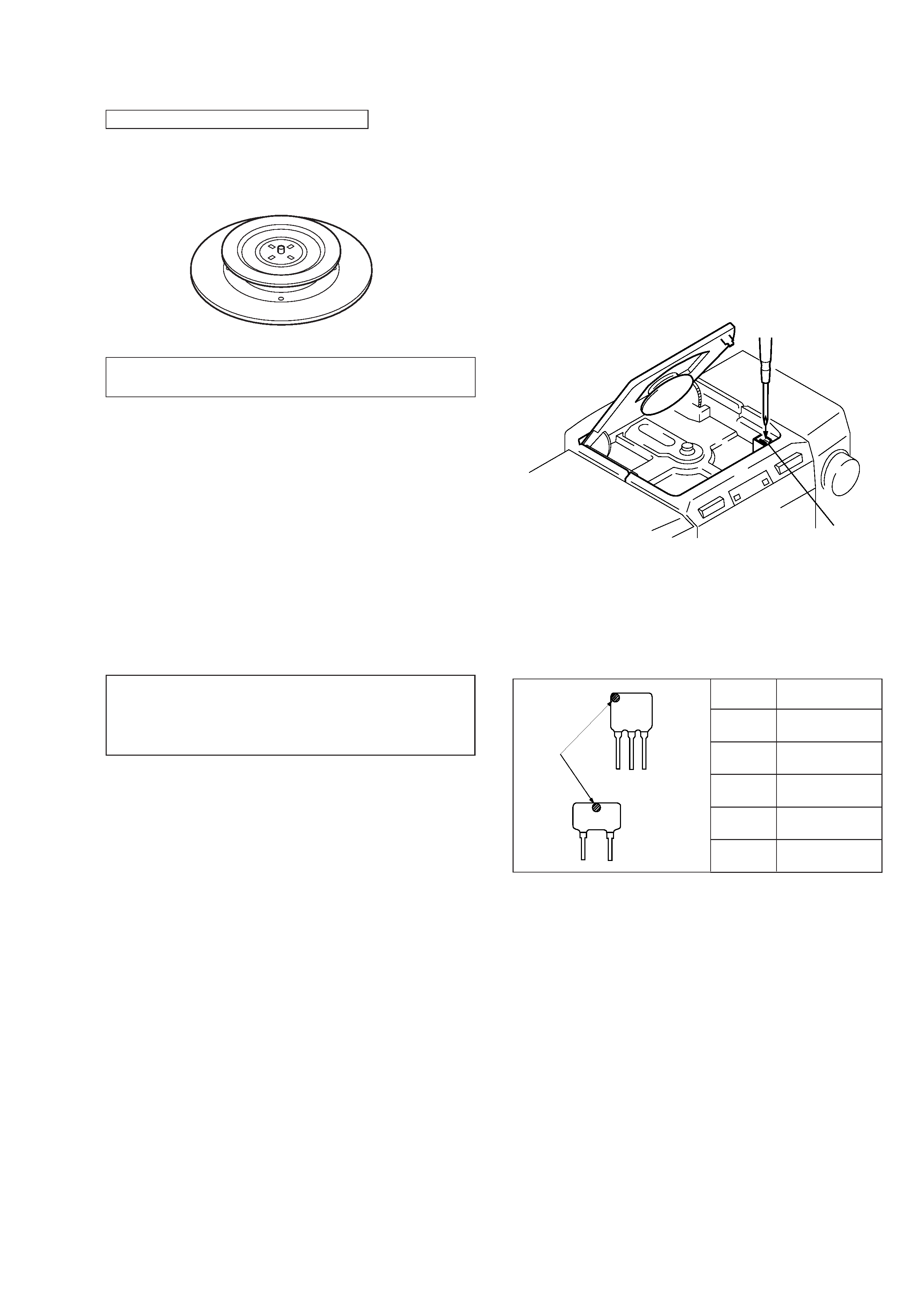
CHUCK PLATE JIG ON REPAIRING
On repairing CD section, playing a disc without the CD lid, use
Chuck Plate Jig.
· Code number of Chuck Plate Jig: X-4918-255-1
S701
CF1, 2
CF3
mark
Mark
Center frequency
red
10.70 MHz
blue
10.67 MHz
orange
10.73 MHz
black
10.64 MHz
white
10.76 MHz
HOW TO CHANGED THE CERAMIC FILTERS
This model is used three ceramic filters of CF1, CF2 and CF3.
You must used same type of color marked ceramic filters in order
to meet same specifications.
Therefore, the ceramic filter must changed three pieces together
since it's supply three pieces in one package as a spare parts.
4
SECTION 2
GENERAL
This section is extracted from
instruction manual.
5