
MICROFILM
SERVICE MANUAL
CORDLESS TELEPHONE
US Model
Canadian Model
SPECIFICATIONS
SPP-SS966
General
Spread method
Direct-Sequence Spread-Spectrum
Access method
FDMA-TDD
Frequency band
902-928 MHz
Operating channel
20 channels
Dial signal
Tone, 10 PPS (pulse) selectable
Supplied accessories
AC power adaptor (AC-T46)
Telephone line cords (2)
Wall bracket/stand for base phone
Rechargeable battery pack (BP-T24)
Directories
Handset
Power source
Rechargeable battery pack BP-T24
Battery life
Standby: Approx. 10 days (RING ON mode)
Approx. A month (RING OFF mode)
Talk:
Approx. 6 hours
Dimensions
Approx. 58 x 177 x 46 mm (w / h / d),
antenna excluded
(approx. 2 3/8 x 7 x 1 13/16 inches)
Antenna: Approx. 72 mm
(approx. 2 7/8 inches)
Mass
Approx. 250 g
(approx. 8.8 oz), battery included
Base phone
Power source
DC 9V from AC power adaptor
AC-T46
Battery charging time
Approx. 12 hours
Dimensions
Approx. 170 x 60 x 214 mm (w / h / d),
antenna excluded
(approx. 6 3/4 x 2 3/8 x 8 1/2 inches)
Antenna: Approx. 165 mm
(approx. 6 1/2 inches)
Mass
Approx. 580 g
(approx. 1 lb 4 oz), wall bracket excluded
Design and specifications are subject to
change without notice.

2
Notes on chip component replacement
· Never reuse a disconnected chip component.
· Notice that the minus side of a tantalum capacitor may be dam-
aged by heat.
ATTENTION AU COMPOSANT AYANT RAPPORT
À LA SÉCURITÉ!
LES COMPOSANTS IDENTIFIÉS PAR UNE MARQUE 0
SUR LES DIAGRAMMES SCHÉMATIQUES ET LA LISTE
DES PIÈCES SONT CRITIQUES POUR LA SÉCURITÉ
DE FONCTIONNEMENT. NE REMPLACER CES COM-
POSANTS QUE PAR DES PIÈCES SONY DONT LES
NUMÉROS SONT DONNÉS DANS CE MANUEL OU
DANS LES SUPPLÉMENTS PUBLIÉS PAR SONY.
SAFETY-RELATED COMPONENT WARNING!!
COMPONENTS IDENTIFIED BY MARK 0 OR DOTTED
LINE WITH MARK 0 ON THE SCHEMATIC DIAGRAMS
AND IN THE PARTS LIST ARE CRITICAL TO SAFE
OPERATION. REPLACE THESE COMPONENTS WITH
SONY PARTS WHOSE PART NUMBERS APPEAR AS
SHOWN IN THIS MANUAL OR IN SUPPLEMENTS PUB-
LISHED BY SONY.
TABLE OF CONTENTS
1.
SERVICING NOTES ............................................... 3
2.
GENERAL
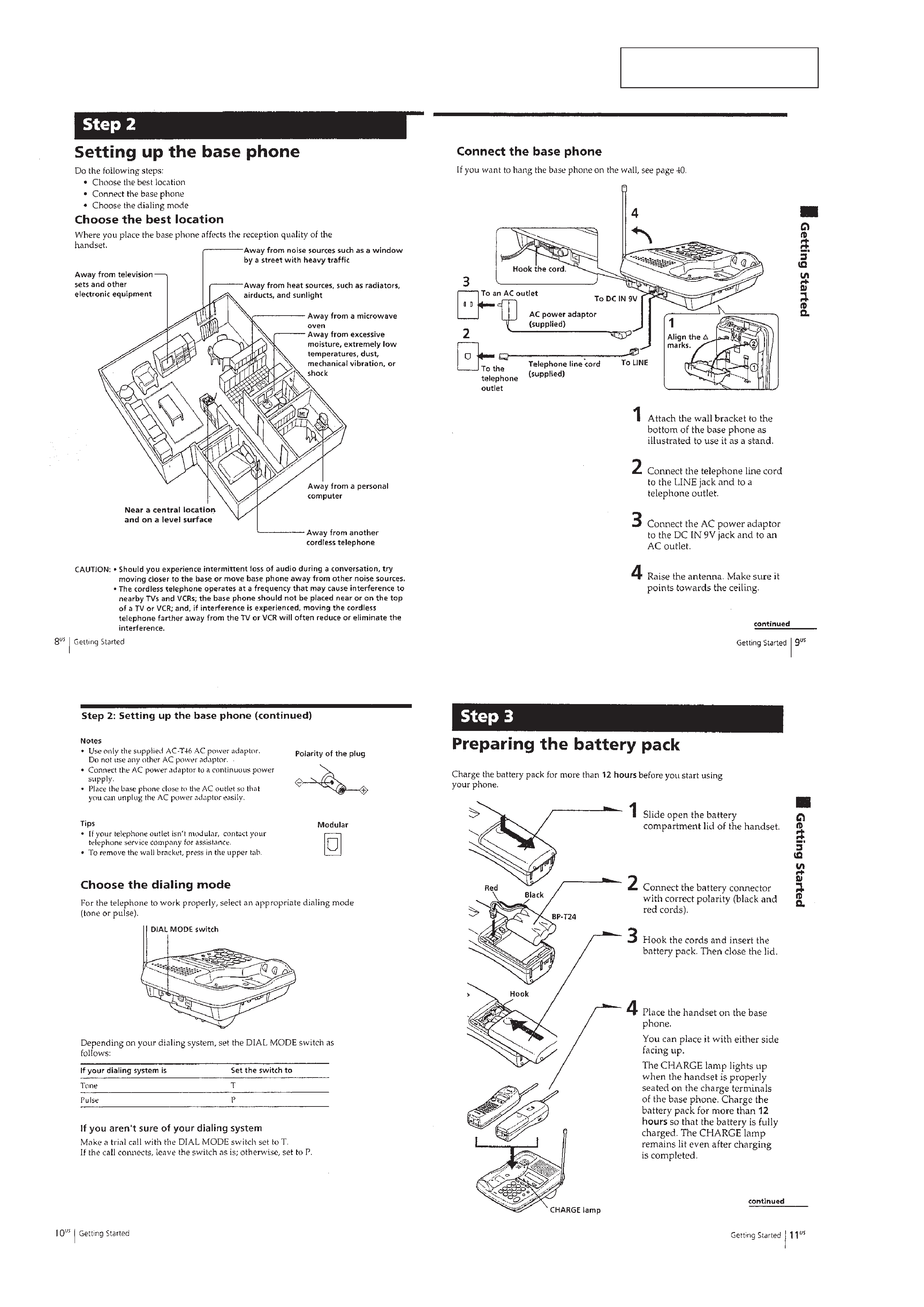
Setting Up the Base Phone .............................................
4
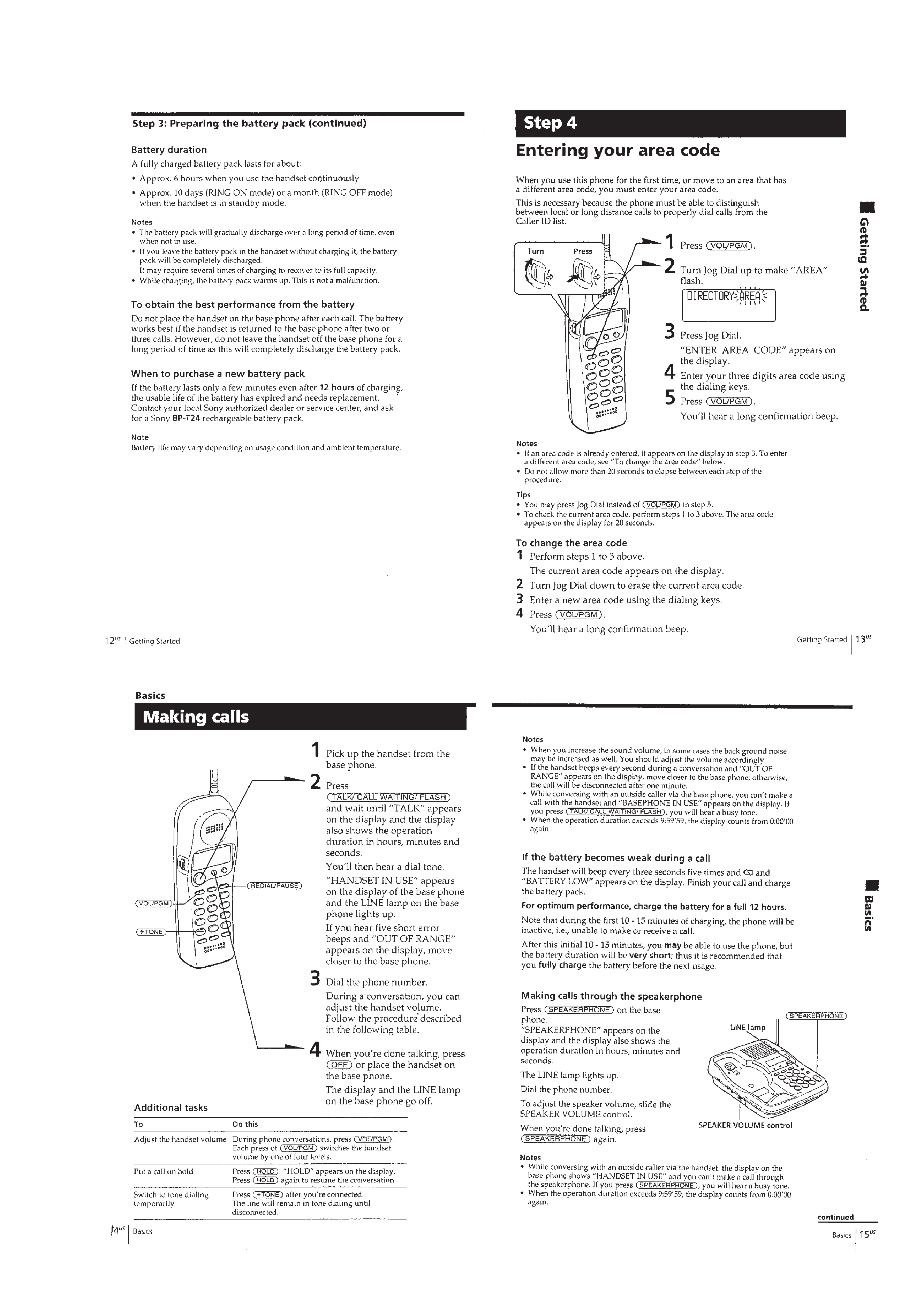
Preparing the Battery Pack .............................................
4
Entering Your Area Code ................................................
5
Making Calls ...................................................................
5
Receiving Calls ...............................................................
6
One-Touch Dialing ..........................................................
6
Speed Dialing ..................................................................
7
Phone Directory ..............................................................
7
Switching the Phones During a Call ...............................
8
Talking between the Phones (Intercom) .........................
9
Voice Paging ....................................................................
9
Transferring a Call ..........................................................
9
Understanding the Caller ID Service .............................. 10
Looking at the Caller ID List .......................................... 10
Using the Caller ID List .................................................. 11
Using "Caller ID with Call Waiting" Service ................ 11
3.
DISASSEMBLY ......................................................... 12
4.
900 MHz SYSTEM OPERATION
4-1. Access Method ................................................................ 15
4-2. Protocol ........................................................................... 15
5.
TEST MODE
5-1. Base Unit ......................................................................... 18
5-2. Handset ............................................................................ 19
5-3. RF Testing ....................................................................... 20
6.
ELECTRICAL ADJUSTMENTS
6-1. Base Unit Section ............................................................ 22
6-2. Handset Section ............................................................... 23
7.
DIAGRAMS
7-1. Block Diagram BASE UNIT Section (1/2) .............. 26
7-2. Block Diagram BASE UNIT Section (2/2) .............. 27
7-3. Block Diagram HANDSET Section ......................... 28
7-4. Notes for Printed Wiring Boards
and Schematic Diagrams ................................................ 29
7-5. Printed Wiring Boards
BASE MAIN Board (Side A)/
BASE MIC Board ........................................................ 30
7-6. Printed Wiring Board
BASE MAIN Board (Side B) ................................... 31
7-7. Schematic Diagram BASE MAIN Section (1/3) ..... 32
7-8. Schematic Diagram BASE MAIN Section (2/3) ..... 33
7-9. Schematic Diagram BASE MAIN Section (3/3) ..... 34
7-10. Printed Wiring Board BASE KEY Section ............. 35
7-11. Schematic Diagram BASE KEY Section ................ 36
7-12. Printed Wiring Board BASE LCD Section ............. 37
7-13. Schematic Diagram BASE LCD Section ................ 37
7-14. Printed Wiring Board HAND MAIN Section ......... 38
7-15. Schematic Diagram HAND MAIN Section ............ 39
7-16. IC Pin Function Description ........................................... 41
8.
EXPLODED VIEWS ................................................ 47
9.
ELECTRICAL PARTS LIST ............................... 49
3
SECTION 1
SERVICING NOTES
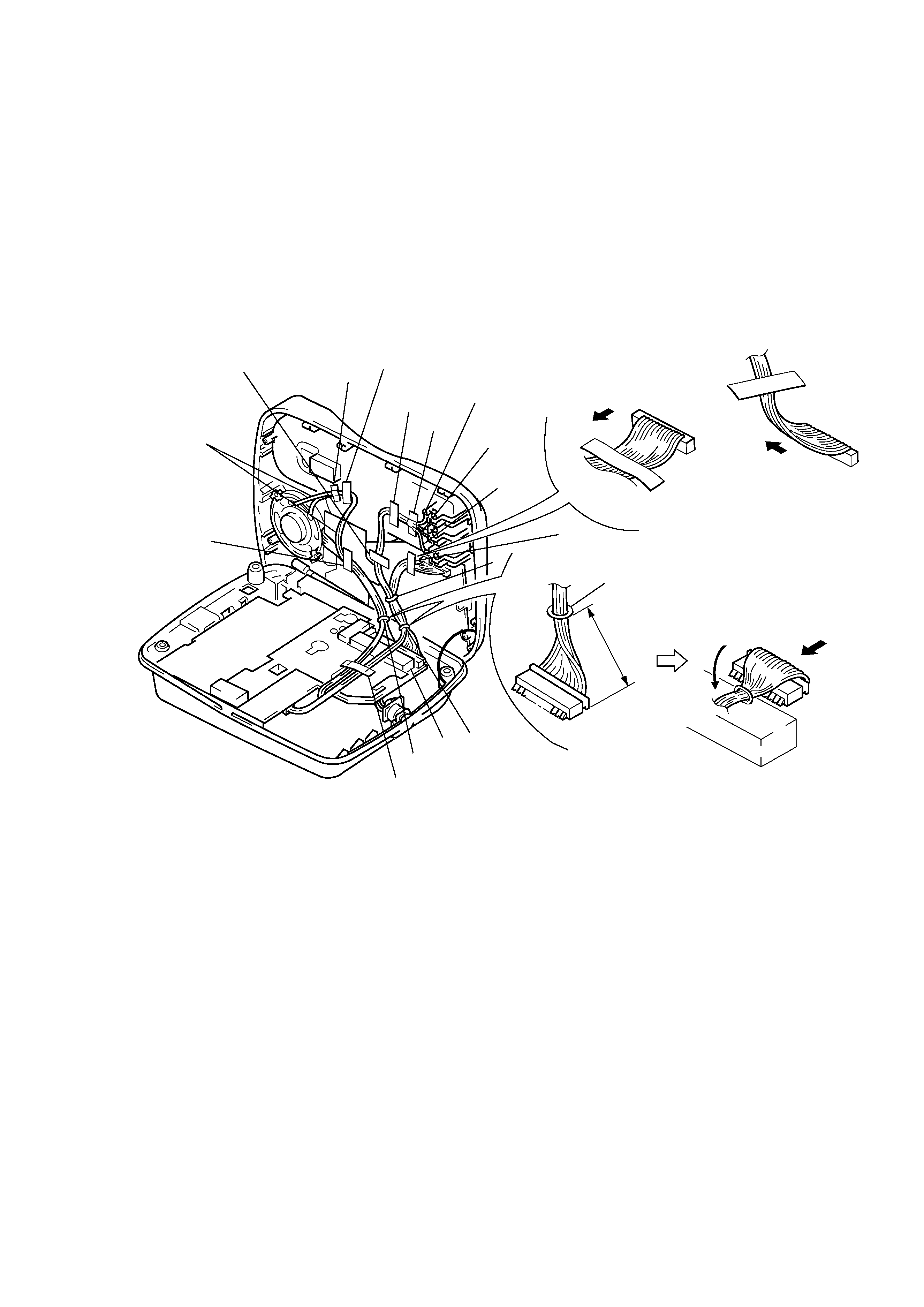
CABLE FASTENING METHOD
· TDD noise may be generated in the intercom or handset speech
depending on how the cables are fastened, and therefore fasten
the cables as shown below.
1
Erect the cabinet (upper) 90 degrees.
2
Insert the wires in the ribs at A and B.
3
Clamp them at C to E.
4
Affix the sponges at F positions.
5
Fix the cables with tapes at G to L positions.
Cable fasting direction
Cable fasting direction
OK
NG
Note:Make sure the wires do not
rise above the sponge and
shield plate.
A
G
L
K
F
J
E
D
I
C
D
, E
H
B
Note:Tape over the
diode (D1001).
Note:Make sure the wires
do not rise.
black
red
90
°
white
Cable fasting direction
clamp stopper
2
cm
4
SECTION 2
GENERAL
This section is extracted from
instruction manual.
5