MICROFILM
SERVICE MANUAL
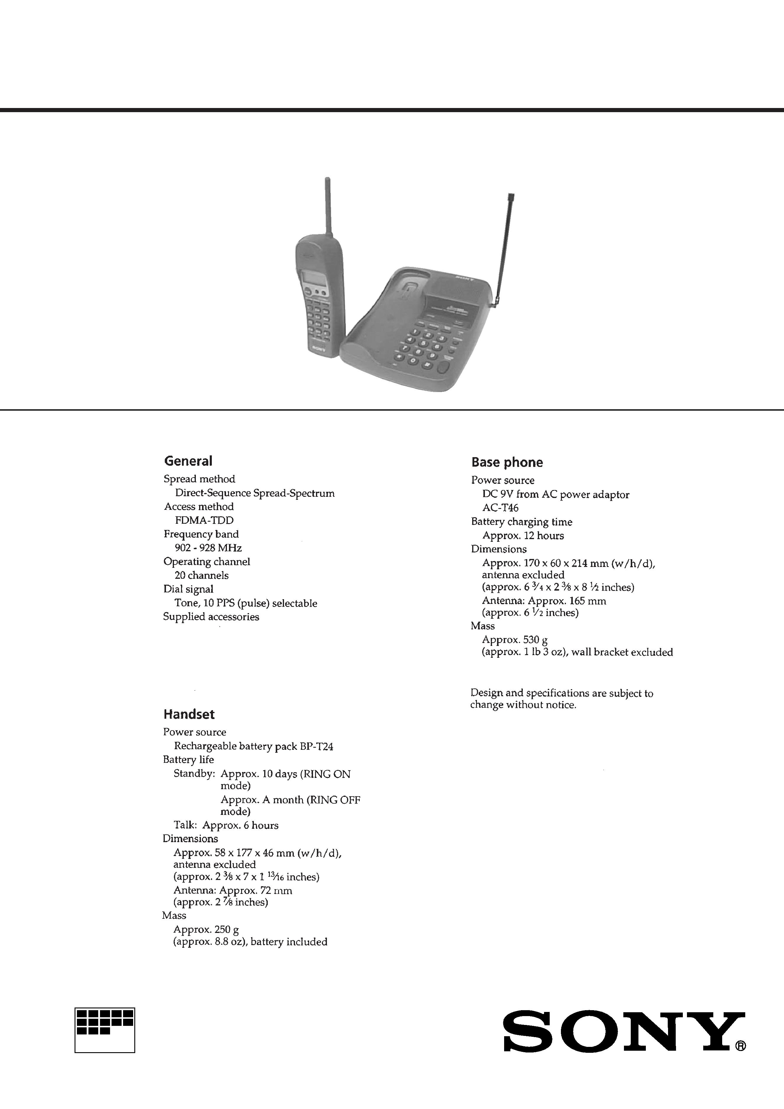
CORDLESS TELEPHONE
E Model
SPECIFICATIONS
SPP-SS964
AC power adaptor (AC-T46)
Telephone line cord
Wall bracket/stand for base phone
Rechargeable battery pack (BP-T24)
Directories

2
TABLE OF CONTENTS
1.
SERVICING NOTES ............................................... 3
2.
GENERAL
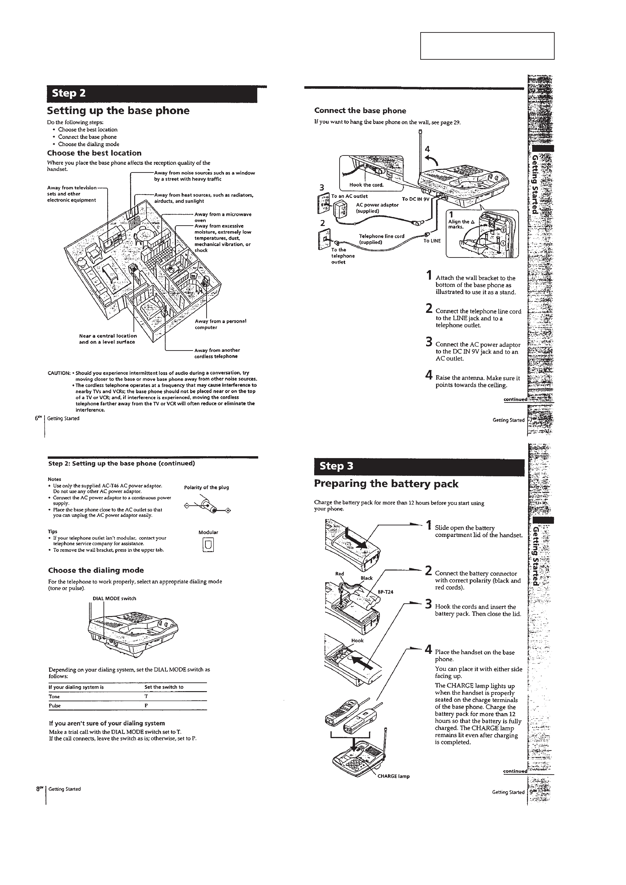
Setting up the base phone ...............................................
4
Preparing the battery pack ..............................................
4
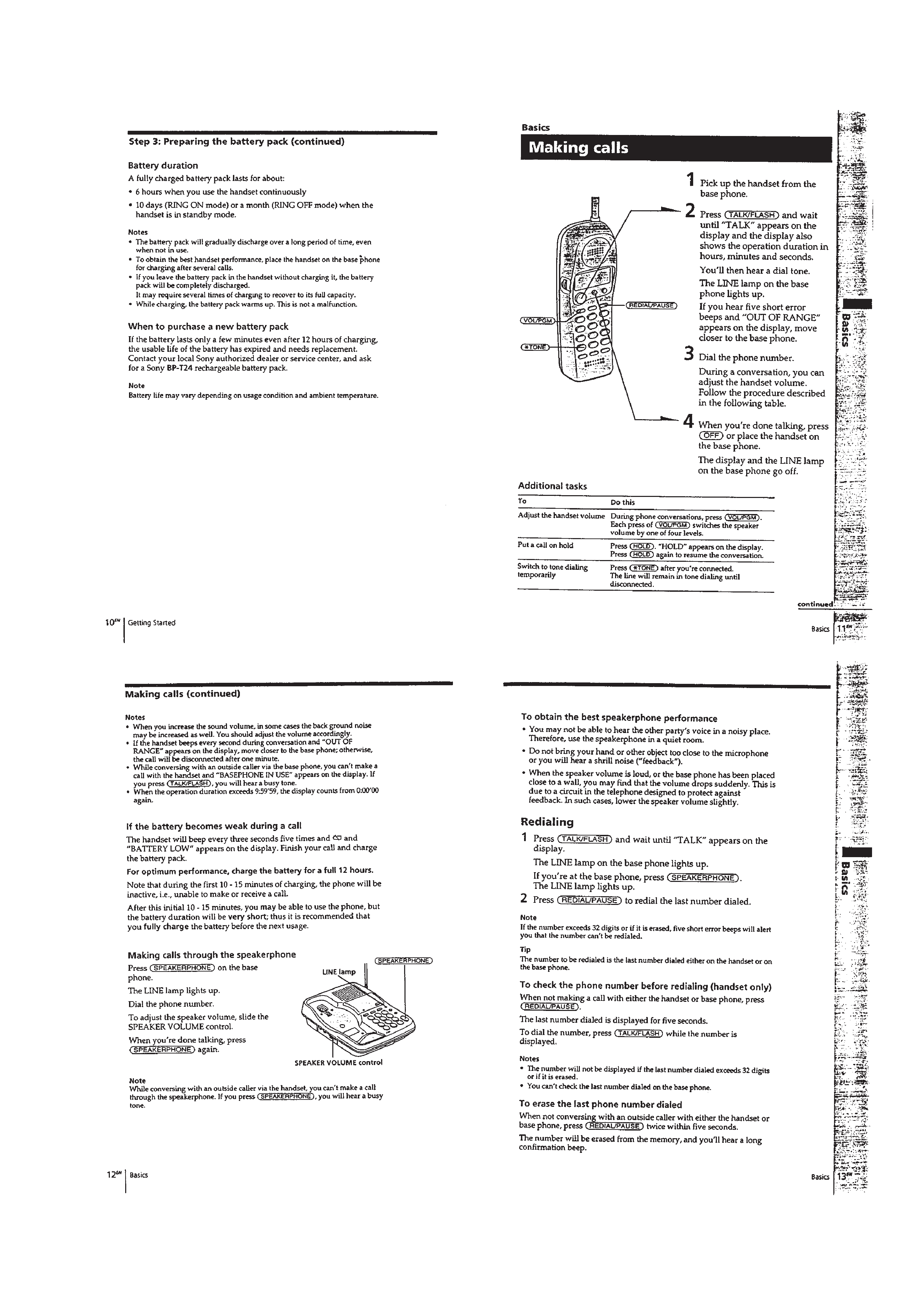
Making calls ....................................................................
5
Receiving calls ................................................................
6
One-touch dialing ............................................................
6
Speed dialing ...................................................................
7
Phone directory ...............................................................
7
Switching the phones during a call .................................
8
Talking between the phones (Intercom) .........................
8
Voice paging ....................................................................
9
Transferring a call ...........................................................
9
3.
DISASSEMBLY ......................................................... 10
4.
900 MHz SYSTEM OPERATION
4-1. Access Method ................................................................ 13
4-2. Protocol ........................................................................... 13
5.
TEST MODE
5-1. Base Unit Section ............................................................ 16
5-2. Handset Section ............................................................... 17
5-3. RF Testing ....................................................................... 18
6.
ELECTRICAL ADJUSTMENTS
6-1. Base Unit Section ............................................................ 20
6-2. Handset Section ............................................................... 21
7.
DIAGRAMS
7-1. Block Diagram BASE UNIT Section ....................... 25
7-2. Block Diagram HANDSET Section ......................... 27
7-3. Notes for Printed Wiring Boards
and Schematic Diagrams ................................................ 29
7-4. Printed Wiring Board
BASE MAIN Board (Side A)/
BASE MICROPHONE Board ..................................... 31
7-5. Printed Wiring Board
BASE MAIN Board (Side B) ................................... 33
7-6. Schematic Diagram BASE MAIN Section (1/3) ...... 35
7-7. Schematic Diagram BASE MAIN Section (2/3) ...... 37
7-8. Schematic Diagram BASE MAIN Section (3/3) ...... 39
7-9. Printed Wiring Board BASE KEY Section ............. 41
7-10. Schematic Diagram BASE KEY Section ................ 42
7-11. Printed Wiring Board HAND MAIN Section ......... 43
7-12. Schematic Diagram HAND MAIN Section ............ 45
7-13. IC Pin Function Description ........................................... 48
8.
EXPLODED VIEWS ................................................ 53
9.
ELECTRICAL PARTS LIST ............................... 55
Notes on chip component replacement
· Never reuse a disconnected chip component.
· Notice that the minus side of a tantalum capacitor may be dam-
aged by heat.
SAFETY-RELATED COMPONENT WARNING!!
COMPONENTS IDENTIFIED BY MARK
! OR DOTTED
LINE WITH MARK
! ON THE SCHEMATIC DIAGRAMS
AND IN THE PARTS LIST ARE CRITICAL TO SAFE
OPERATION. REPLACE THESE COMPONENTS WITH
SONY PARTS WHOSE PART NUMBERS APPEAR AS
SHOWN IN THIS MANUAL OR IN SUPPLEMENTS PUB-
LISHED BY SONY.
3
SECTION 1
SERVICING NOTES
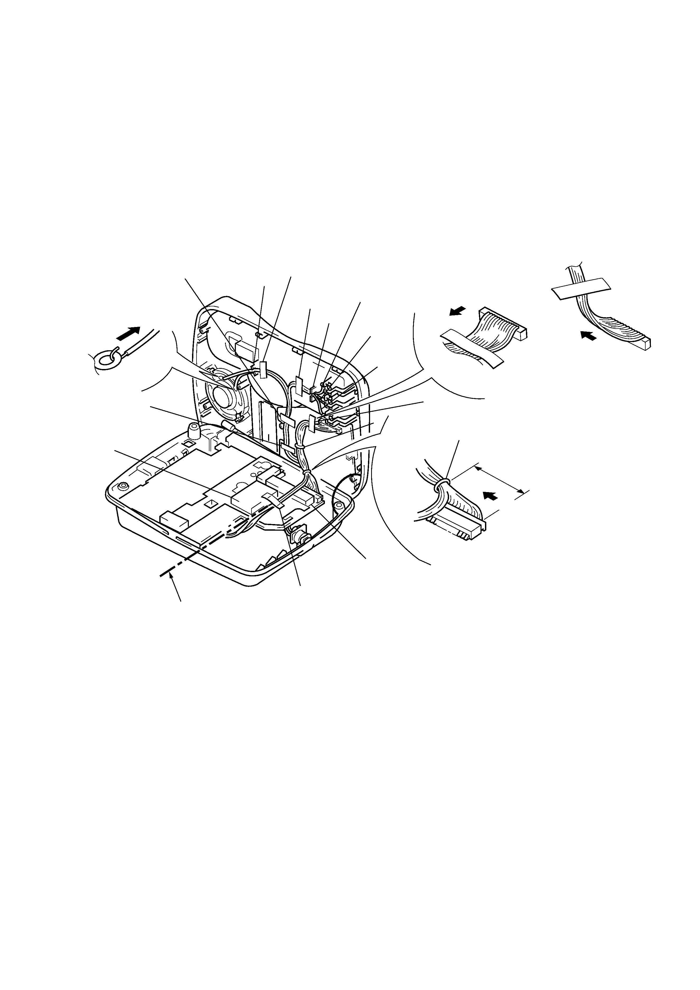
CABLE FASTENING METHOD
· TDD noise may be generated in the intercom or handset speech
depending on how the cables are fastened, and therefore fasten
the cables as shown below.
1 Erect the cabinet (upper) 90 degrees.
2 Insert the wires in the ribs at A and B.
3 Clamp them at C and D.
4 Affix the sponges at E and F positions.
5 Fix the cables with tapes at G to L positions.
Cable fasting direction
Cable fasting direction
OK
NG
Note:Make sure the wires do not
rise above the shield plate.
A
G
L
K
F
J
E
I
D
H
B
Note:Tape over the
diode (D1001).
Direction for drawing
speaker lead wires
black
white
90
°
red
C clamp stopper
Cable fasting direction
25~30
mm
Affix position
Bottom flushed
4
SECTION 2
GENERAL
This section is extracted from
instruction manual.
5