SERVICE MANUAL
CORDLESS HANDSET
US Model
Canadian Model
SPECIFICATIONS
SPP-H273
Ver 1.1 2001.08
9-873-163-02
Sony Corporation
2001H0500-1
Personal Audio Company
C
2001.8
Shinagawa Tec Service Manual Production Group
General
Spread method
Direct-Sequence Spread-Spectrum
Access method
FDMA-TDD
Frequency band
2.4075 - 2.4720 GHz
Operating channel
40 channels
Supplied accessories
Charger/AC power adaptor (AC-T127)
Rechargeable battery pack (BP-T38)
Sticker (for station number/Answering function)
(1 sheet)
Cordless handset
Power source
Rechargeable battery pack BP-T38
Battery life
Standby: Approx. 6 days
Talk: Approx. 5 hours
Battery charging time
Approx. 12 hours
Dimensions
Approx. 2 3/8 x 6 5/8 x 1 15/16 inches (w/h/d), antenna
excluded (approx. 58 x 166 x 48 mm)
Antenna: Approx. 2 7/8 inches (approx. 72 mm)
Mass
Approx. 8.1 oz (approx. 230 g), battery included
Charger
Power source
DC 9 V from AC power adaptor
AC-T127
Dimensions
Approx. 3 1/4 x 2 5/8 x 4 1/8 inches (w/h/d)
(approx. 80 x 64 x 102 mm)
Mass
Approx. 2.7 oz (approx. 75 g)
Design and specifications are subject to change without notice.
2
SPP-H273
TABLE OF CONTENTS
1.
SERVICING NOTES ............................................... 3
2.
GENERAL
Identifying the Parts ........................................................
4
Registering a cordless handset ........................................
6
3.
DISASSEMBLY
3-1. Disassembly Flow ...........................................................
7
3-2. Cabinet (Rear) .................................................................
7
3-3. Hand Main Board ............................................................
7
4.
TEST MODE .............................................................. 8
5.
ELECTRICAL ADJUSTMENTS ......................... 13
6.
DIAGRAMS
6-1. Note for Printed Wiring Boards and
Schematic Diagrams ....................................................... 14
6-2. Block Diagram ................................................................ 15
6-3. Printed Wiring Board HAND MAIN Board ........... 16
6-4. Schematic Diagram HAND MAIN Board (1/2) ..... 17
6-5. Schematic Diagram HAND MAIN Board (2/2) ..... 18
6-6. IC Pin Function Description ........................................... 20
7.
EXPLODED VIEW ................................................... 22
8.
ELECTRICAL PARTS LIST ............................... 23
SAFETY-RELATED COMPONENT WARNING!!
COMPONENTS IDENTIFIED BY MARK 0 OR DOTTED
LINE WITH MARK 0 ON THE SCHEMATIC DIAGRAMS
AND IN THE PARTS LIST ARE CRITICAL TO SAFE
OPERATION. REPLACE THESE COMPONENTS WITH
SONY PARTS WHOSE PART NUMBERS APPEAR AS
SHOWN IN THIS MANUAL OR IN SUPPLEMENTS PUB-
LISHED BY SONY.
Notes on chip component replacement
· Never reuse a disconnected chip component.
· Notice that the minus side of a tantalum capacitor may be dam-
aged by heat.
ATTENTION AU COMPOSANT AYANT RAPPORT
À LA SÉCURITÉ!
LES COMPOSANTS IDENTIFIÉS PAR UNE MARQUE 0
SUR LES DIAGRAMMES SCHÉMATIQUES ET LA LISTE
DES PIÈCES SONT CRITIQUES POUR LA SÉCURITÉ
DE FONCTIONNEMENT. NE REMPLACER CES COM-
POSANTS QUE PAR DES PIÈCES SONY DONT LES
NUMÉROS SONT DONNÉS DANS CE MANUEL OU
DANS LES SUPPLÉMENTS PUBLIÉS PAR SONY.
NOTE FOR REPLACEMENT OF THE CRYSTAL VI-
BRATOR ON THE HAND MAIN BOARD
There are two types of crystal vibrators used on the HAND MAIN
board. Accordingly, when replacing the crystal vibrator, replace
the following reference number parts together. Similarly, when
the following reference number parts are replaced, check which
type of crystal vibrator is used and use the same type.
Crystal
Ref. No.
TYPE A
TYPE B
vibrator
C11
18PF
33PF
X31
C12
18PF
22PF
R40
1.5k
1k
[How to identify the TYPE A or B of crystal vibrator]
The type A or B can be identified from the initial character of a
character staring indicated on the top surface of the parts.
TYPE A: Starting with a numeric value
TYPE B: Staring with alphabet D
Ver 1.1

3
SPP-H273
SECTION 1
SERVICING NOTES
IF AN ERROR MESSAGE IS DISPLAYED
If the following error message is displayed after the power was turned on, check the items where "1" is indicated.
· Note on Replacing The EEPROM
After the EEPROM was replaced, write various parameters in the "TEST MODE E" (see page 9). (For the ID, see "Writing ID Numbers"
described below)
Note: Replacing the EEPROM causes all data such as customer registered telephone directory to be cleared.
RE-REGISTERING ALREADY REGISTERED SET
Initialize the registered information on this set, and then register again this set by the method given below. When re-registering the handset,
refer to "Registering additional cordless handsets" in the instruction manual. (see page 6)
1. Turn the power on.
2. Press three keys of [1], [EZ ACCESS], and [INTERCOM] simultaneously.
WRITING ID NUMBERS (for registering handsets)
The ID numbers are given in decimal notation on the bottom of base unit. If handsets are registered, ID can be written in the TEST mode,
but the TEST mode handles ID numbers in hexadecimal notation, thus requiring decimal numbers to be converted into hexadecimal
numbers. Accordingly, when registering this set, refer to "Registering a cordless handset" in the instruction manual. (see page 6)
However, if the EEPROM was replaced, the handsets cannot be registered by the method mentioned above. In such a case, enter various
parameters except ID numbers in the "TEST MODE E", and then register the handsets by the method given in the instruction manual.
Also, the ID numbers can be written in the "TEST MODE B"(decimal number) (see page 10).
ERROR=[][][][][][]00
EEPROM
*1 data error
Write correct data to the EEPROM.
ID error
Write correct ID data.
Flash memory (IC403)
*2 data error
Replace the flash memory (IC403).
Flash memory (IC403)
*2 error
Check the flash memory (IC403) and its peripheral circuits.
DSP (IC402)
*2 error
Check the DSP (IC402) and its peripheral circuits.
EEPROM
*1 error
Check the EEPROM and its peripheral circuits.
*1) Base unit: IC303, Handset: IC122
*2) Base unit only
4
SPP-H273
SECTION 2
GENERAL
This section is extracted from
instruction manual.
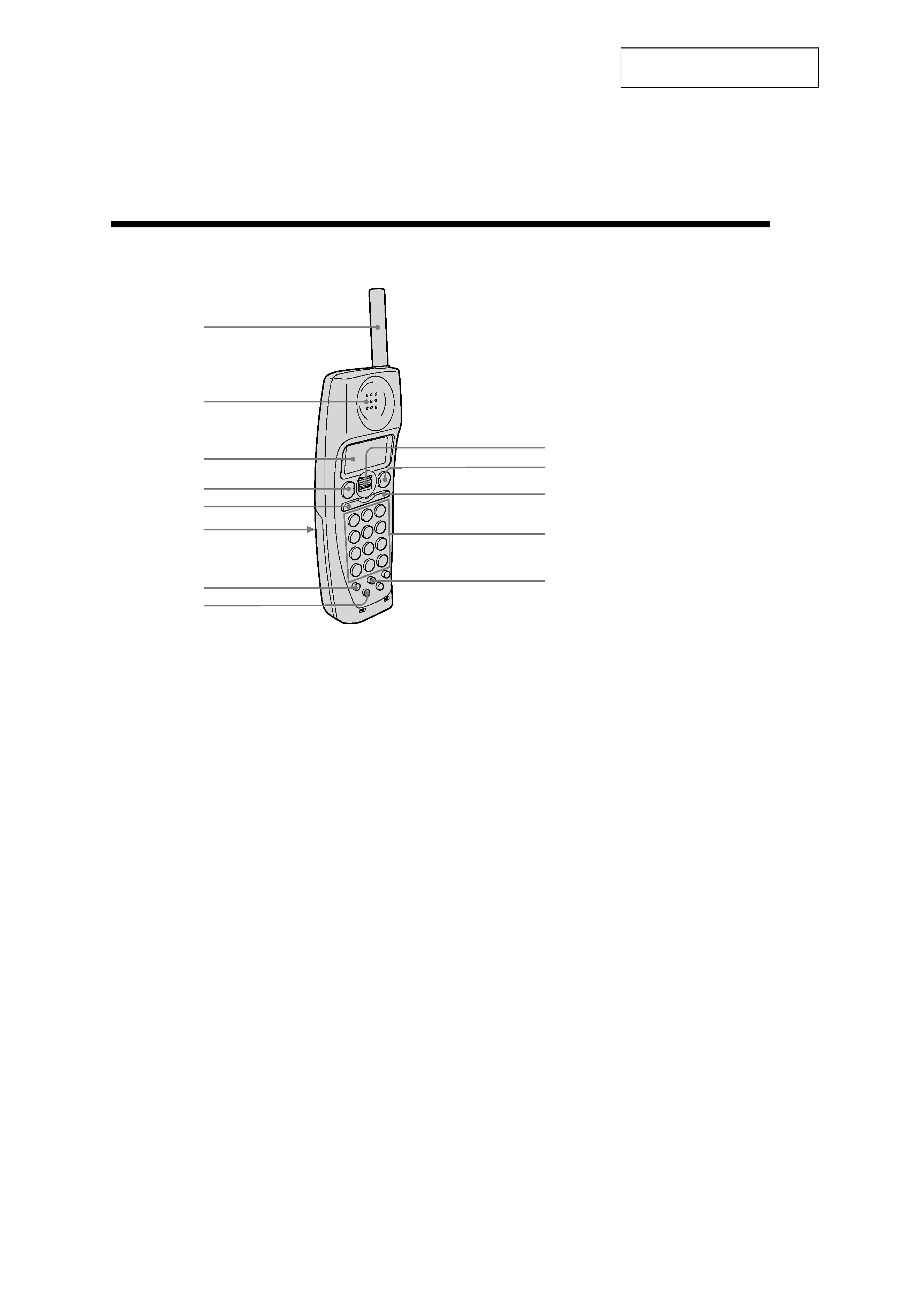
Identifying the parts
1
Antenna
2
Speaker
3
Display window
4
TALK button
Lets you make or receive a call.
5
HOLD/PLAY button
Puts a call on hold/plays back
recorded messages.
6
Battery compartment
7
CALLWAITING/FLASH button
Switches to a second call if you
have "call waiting" service, or lets
you make a new call.
Cordless handset
8
EZ ACCESS button
Lets you make a call with the
registered access number.
9
Jog Dial
0
OFF button
Allows you to disconnect the call.
qa
INTERCOM button
Lets you talk between the base
phone and the cordless handset.
qs
Dialing keys
qd
ERASE button
1
qs
qd
2
3
4
5
6
7
8
9
0
qa
5
SPP-H273
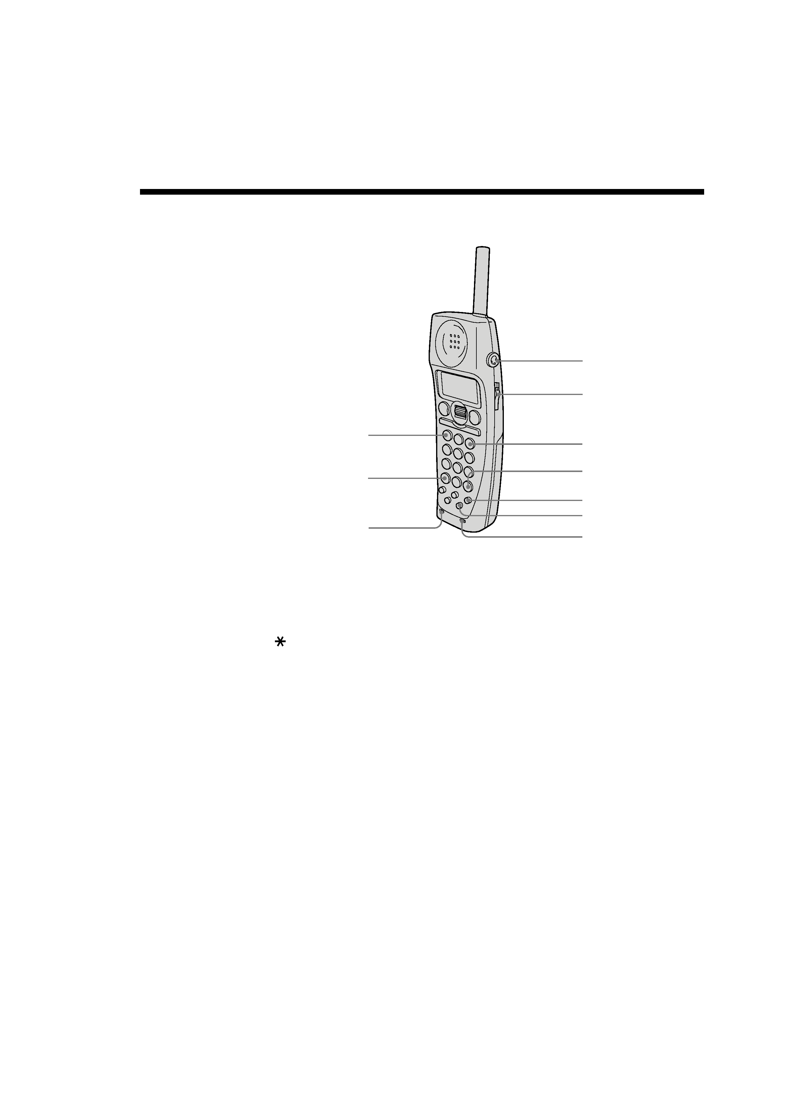
qf
REPEAT . button
Press once to repeat the current
message or twice to go back to the
previous message.
qg
TONE button
Allows you to switch temporarily to
tone dialing.
qh
RINGER
qj
I
(HEADSET) jack
qk
VOL (volume) switch
Adjust the cordless handset
volume.
ql
SKIP > button
Press to skip to the next message.
ws
wd
qh
qj
qk
ql
w;
wa
qf
qg
w;
#
button
Used to change the number of
digits of the phone number in the
Caller ID list.
wa
PGM (program) button
ws
REDIAL/PAUSE button
Redials one of the last five numbers
called/inserts a pause in the dialing
sequence.
wd
MIC (Microphone)