http://cxema.ru
CHASSIS
SERVICE MANUAL
SPECIFICATIONS
GDM-F520
CR1
AEP Model
US Model
Canadian Model
Chassis No. SCC-L33D-A
TORINITORON® COLOR GRAPHIC DISPLAY
CRT
0.22 mm aperture grille pitch, 90-degree deflection, FD Trinitron
21 inches measured diagonally
Viewable image size
Approx. 403.8
× 302.2 mm (w/h) (16 × 12 inches)
19.8" viewing image
Resolution (H:Horizontal, V:Vertical)
Maximum: H: 2048 dots, V: 1536 lines
Recommended: H: 1600 dots, V: 1200 lines
Input signal levels
Video signal:
Analog RGB: 0.700 Vp-p (positive), 75
SYNC signal: H/V separate or composite sync:
TTL 2 k
, Polarity free
Sync on Green: 0.3 Vp-p (negative)
Standard image area
Approx. 388
× 291 mm (4:3)
(15 3/8
× 11 1/2 inches) or
Approx. 364
× 291 mm (5:4)
(14 3/8
× 11 1/2 inches)
Deflection frequency (H:Horizontal, V:Vertical)
H: 30 to 137 kHz, V: 48 to 170 Hz
AC input voltage/current
100 to 240 V, 50 60 Hz, 2.0 1.0 A
Power Consumption (with no USB devices connected)
Approx. 145 W
Operating temperature
10 ºC to 40 ºC
Dimensions
Approx. 497
× 499 × 487 mm (w/h/d)
(19 5/8
× 19 3/4 × 19 1/4 inches)
Mass
Approx. 30 kg (66 lb 2 oz)
Plug and Play
DDC2B/DDC2Bi
Supplied accessories
Power cord
HD15 video signal cable
USB cable
Exclusive Power Mac G3/G4 adapter
This instruction manual
Design and specifications are subject to change without notice.
http://cxema.ru
GDM-F520(E)
2
LEAKAGE
TEST
The
AC
leakage
from
any
exposed
metal
part
to
earth
ground
and
from
all
exposed
metal
parts
to
any
exposed
metal
part
having
a
return
to
chassis,
must
not
exceed
0.5
mA
(500
microamperes).
Leakage
current
can
be
measured
by
any
one
of
three
methods.
1.
A
commercial
leakage
tester,
such
as
the
Simpson
229
or
RCA
WT-
540A.
Follow
the
manufacturers'
instructions
to
use
these
instruments.
2
.
A
battery-operated
AC
milliammeter.
The
Data
Precision
245
digital
multimeter
is
suitable
for
this
job.
3.
Measuring
the
voltage
drop
across
a
resistor
by
means
of
a
VOM
or
battery-operated
AC
voltmeter.
The
"limit"
indication
is
0.75
V,
so
analog
meters
must
have
an
accurate
low-voltage
scale.
The
Simpson
250
and
Sanwa
SH-63Trd
are
examples
of
a
passive
VOMs
that
are
suitable.
Nearly
all
battery
operated
digital
multimeters
that
have
a
2
V
AC
range
are
suitable.
(See
Fig.
A)
After
correcting
the
original
service
problem,
perform
the
following
safety
checks
before
releasing
the
set
to
the
customer:
1
.
Check
the
area
of
your
repair
for
unsoldered
or
poorly-soldered
connections.
Check
the
entire
board
surface
for
solder
splashes
and
bridges.
2.
Check
the
interboard
wiring
to
ensure
that
no
wires
are
"pinched"
or
contact
high-wattage
resistors.
3
.
Check
that
all
control
knobs,
shields,
covers,
ground
straps,
and
mounting
hardware
have
been
replaced.
Be
absolutely
certain
that
you
have
replaced
all
the
insulators.
4.
Look
for
unauthorized
replacement
parts,
particularly
transistors,
that
were
installed
during
a
previous
repair.
Point
them
out
to
the
customer
and
recommend
their
replacement.
5
.
Look
for
parts
which,
though
functioning,
show
obvious
signs
of
deterioration.
Point
them
out
to
the
customer
and
recommend
their
replacement.
6
.
Check
the
line
cords
for
cracks
and
abrasion.
Recommend
the
replacement
of
any
such
line
cord
to
the
customer.
7.
Check
the
B+
and
HV
to
see
if
they
are
specified
values.
Make
sure
your
instruments
are
accurate;
be
suspicious
of
your
HV
meter
if
sets
always
have
low
HV.
8.
Check
the
antenna
terminals,
metal
trim,
"metallized"
knobs,
screws,
and
all
other
exposed
metal
parts
for
AC
Leakage.
Check
leakage
as
described
right.
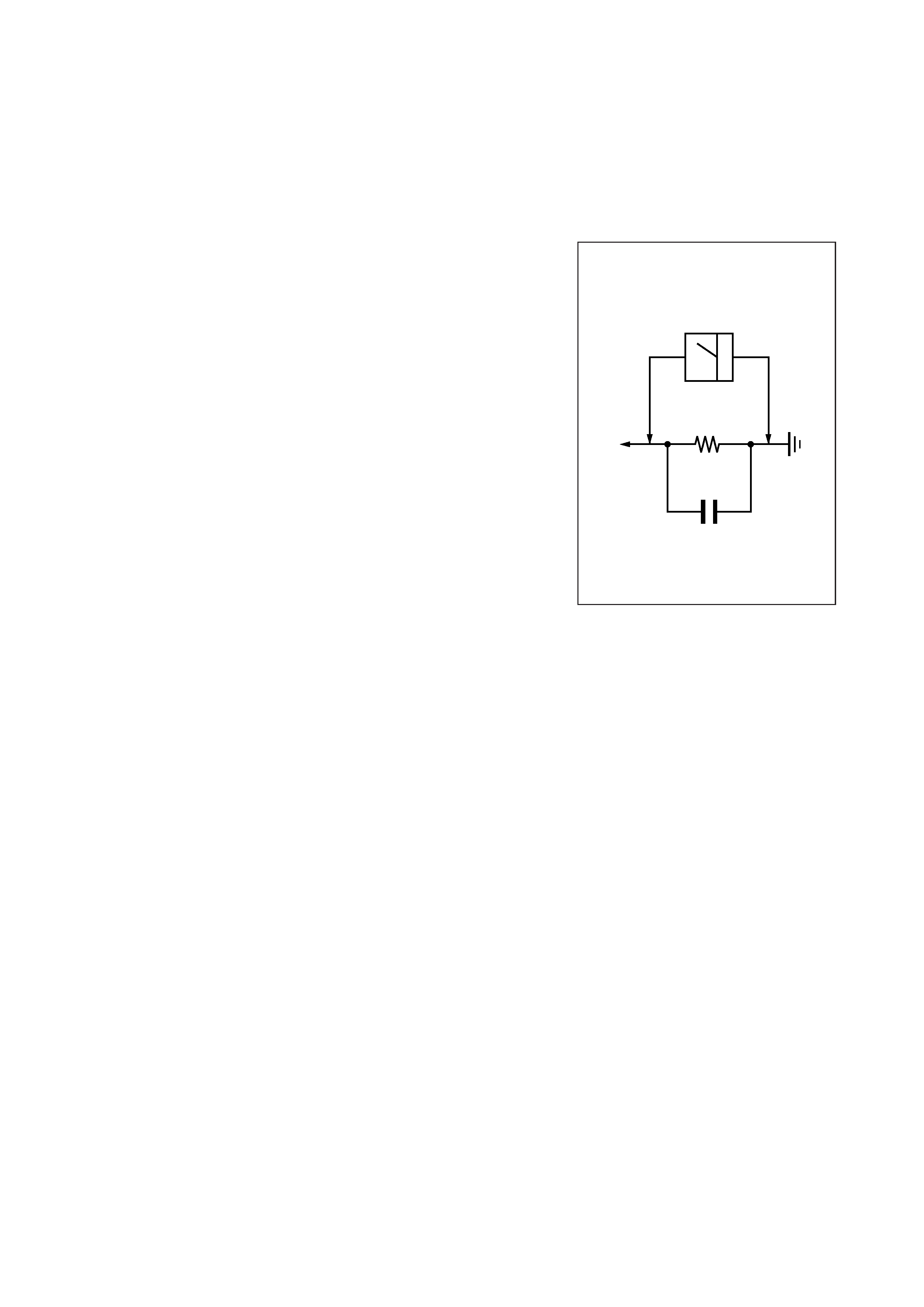
Fig.
A.
Using
an
AC
voltmeter
to
check
AC
leakage.
1.5
k
0.15
µ
F
AC
Voltmeter
(0.75
V)
To
Exposed
Metal
Parts
on
Set
Earth
Ground
SAFETY
CHECK-OUT
http://cxema.ru
GDM-F520(E)
3
WARNING!!
NEVER
TURN
ON
THE
POWER
IN
A
CONDITION
IN
WHICH
THE
DEGAUSS
COIL
HAS
BEEN
REMOVED.
SAFETY-RELATED
COMPONENT
WARNING!!
COMPONENTS
IDENTIFIED
BY
SHADING
AND
MARK
¡
ON
THE
SCHEMATIC
DIAGRAMS,
EXPLODED
VIEWS
AND
IN
THE
PARTS
LIST
ARE
CRITICAL
FOR
SAFE
OPERATION.
REPLACE
THESE
COMPONENTS
WITH
SONY
PARTS
WHOSE
PART
NUMBERS
APPEAR
AS
SHOWN
IN
THIS
MANUAL
OR
IN
SUPPLEMENTS
PUBLISHED
BY
SONY.
CIRCUIT
ADJUST-
MENTS
THAT
ARE
CRITICAL
FOR
SAFE
OPERATION
ARE
IDENTIFIED
IN
THIS
MANUAL.
FOLLOW
THESE
PROCEDURES
WHENEVER
CRITICAL
COMPONENTS
ARE
REPLACED
OR
IM-
PROPER
OPERATION
IS
SUSPECTED.
AVERTISSEMENT!!
NE
JAMAIS
METTRE
SOUS
TENSION
QUAND
LA
BOBINE
DE
DEMAGNETISATION
EST
ENLEVÉE.
ATTENTION
AUX
COMPOSANTS
RELATIFS
À
LA
SÉCURITÉ!!
LES
COMPOSANTS
IDENTIFIÉS
PAR
UNE
TRAME
ET
UNE
MARQUE
¡
SONT
CRITIQUES
POUR
LA
SÉCURITÉ.
NE
LES
REMPLACER
QUE
PAR
UNE
PIÈCE
PORTANT
LE
NUMÉRO
SPECIFIÉ.
LES
RÉGLAGES
DE
CIRCUIT
DONT
L'IMPORTANCE
EST
CRITIQUE
POUR
LA
SÉCURITÉ
DU
FONCTIONNEMENT
SONT
IDENTIFIÉS
DANS
LE
PRÉSENT
MANUEL.
SUIVRE
CES
PROCÉDURES
LORS
DE
CHAQUE
REMPLACEMENT
DE
COMPOSANTS
CRITIQUES,
OU
LORSQU'UN
MAUVAIS
FONCTIONNEMENT
EST
SUSPECTÉ.
Note:
Hand
degauss
must
be
used
on
stand-by
or
power-off
condition.
This
model
has
an
automatic
earth
magnetism
correction
function
by
using
an
earth
magnetism
sensor
and
a
LCC
coil.
When
using
a
hand
degauss
while
monitor
(LCC
coil)
is
being
operated,
it
some-
times
gets
magnetized,
and
the
system
may
not
work
properly
as
a
result.
http://cxema.ru
GDM-F520(E)
4
POWER
SAVING
FUNCTION
This
monitor
meets
the
power-saving
guidelines
set
by
VESA,
TCO'99,
and
E
NERGY
S
TAR.
If
no
signal
is
input
to
the
monitor
from
your
computer,
the
monitor
will
automatically
reduce
power
consumption
as
shown
below.
*
1
Figures
reflect
power
consumption
when
no
USB
compatible
peripherals
are
connected
to
the
monitor.
*
2
When
your
computer
enters
power
saving
mode,
NO
SIGNAL
appears
on
the
screen.
After
a
few
seconds,
the
monitor
enters
power
saving
mode.
*
3
"Deep
sleep"
is
power
saving
mode
defined
by
the
Environmental
Protection
Agency.
P
o
wer
mode
P
o
wer
consumption
*
1
!
(po
wer)
indicator
normal
operation
145
W
green
acti
v
eof
f*
2
(deep
sleep)*
3
3
W
orange
http://cxema.ru
GDM-F520(E)
5
DIAGNOSIS
Failre
+B
failure
Horizontal
/
Vertical
Deflection
failure,
Thermal
protector
ABL
protector
HV
failure
Aging
/
Self
Test
Out
of
scan
range
Power
LED
Amber
Off
(0.5
sec)
(0.5
sec)
Amber
Off
(1.5
sec)
(0.5
sec)
Amber
Off
(0.5
sec)
(1.5
sec)
Amber
Off
Amber
Off
(0.25
sec)
(0.25
sec)
(0.25
sec)
(1.25
sec)
Amber
Off
Green
Off
(0.5
sec)
(0.5
sec)
(0.5
sec)
(0.5
sec)
Green
(OSD
indication)
Aging
Mode
(Video
Aging)
:
During
Power
Save,
press
MENU
button
for
longer
than
2
second.
Self
Test
(OSD
Color
Bar)
:
During
Power
Save,
push
up
Control
button
for
longer
than
2
second.
Reliability
Check
Mode
:
During
Power
Save,
push
down
Control
button
for
longer
than
2
second.