SPECIFICATIONS
Material
Plastic (PC, ABS), glass
Waterproof
Waterproof gasket, buckles
Bult-in microphone
Stereo
Dimension
Approx. 169
× 174 × 261 mm (w/h/d)
(6 3/4
× 6 7/8 × 10 3/8 inches)
Mass
Approx. 990 g (2 lb 3 oz) (only sports
pack)
Supplied accessories
Shoulder strap (1)
Camera mounting shoe (1)
Tripod screw plate (1, pre-installed on the
camera mounting shoe)
Reflex prevention ring Large (1), Small (1)
Grease (1)
Anti-fogging lens solution (1)
Operating Instructions (1)
Design and specifications subject to change
without notice.
SPK-DVF3
AEP Model
SERVICE MANUAL
SPORTS PACK
Ver 1.0 2001. 04
SPK-DVF3
-- 3 --
SECTION 1
PRINTED WIRING BOARD AND SCHEMATIC DIAGRAM
(Measuring conditions voltage and waveform)
· Power voltage is dc 6 V and fed with regulated dc power supply
from CN001 pin
1.
(VOM of DC 10 M
input impedance is used.).
· Voltage values change depending upon input impedance of VOM
used.)
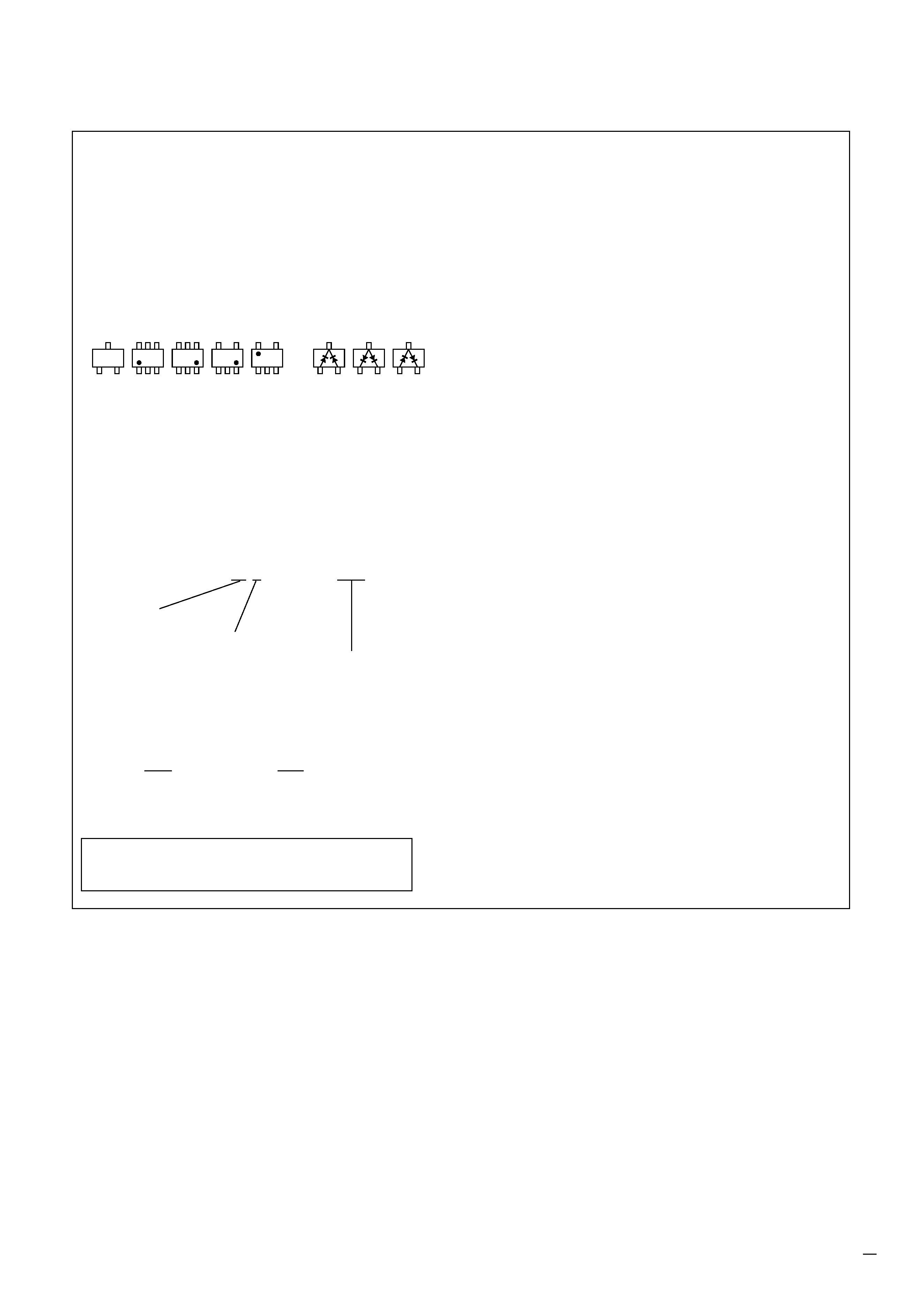
THIS NOTE IS COMMON FOR WIRING BOARDS AND SCHEMATIC DIAGRAMS
(In addition to this, the necessary note is printed in each block)
C
BE
5
64
2
13
5
46
2
31
45
2
31
12
4
53
3
21
3
21
3
21
Transistor
Diode
Kinds of capacitor
Temperature characteristics
External dimensions (mm)
(For printed wiring boards)
·
b: Pattern from the side which enables seeing.
(The other layers' patterns are not indicated.)
· Through hole is omitted.
· Circled numbers refer to waveforms.
· There are few cases that the part printed on diagram isn't
mounted in this model.
· Chip parts.
(For schematic diagrams)
· All capacitors are in
µF unless otherwise noted. pF : µµF. 50V or
less are not indicated except for electrolytics and tantalums.
· Chip resistors are 1/10W unless otherwise noted.
k
=1000, MW=1000k.
· Caution when replacing chip parts.
New parts must be attached after removal of chip.
Be careful not to heat the minus side of tantalum capacitor, Be-
cause it is damaged by the heat.
· Some chip part will be indicated as follows.
Example
C541
L452
22U
10UH
TA A
2520
· Constants of resistors, capacitors, ICs and etc with XX indicate
that they are not used.
In such cases, the unused circuits may be indicated.
· All variable and adjustable resistors have characteristic curve B,
unless otherwise noted.
· Signal name
XEDIT
EDIT PB/XREC PB/REC
·
C : panel designation
·
U : B+ Line
·
J
: IN/OUT direction of (+,) B LINE.
Note :
The components identified by mark
0 or dotted
line with mark
0 are critical for safety.
Replace only with part number specified.
K
K
A
1
A
B
C
234
5
RED
WHT
BLK
1
2
3
TO
VIDEO CAM
LANC JACK
1-670-451-
11
1-670-451-
11
D003
C003
X001
CN001
R020
R010
R015
R016
R017
IC003
14
15
28
1
R013
R021
R009
C005
C002
C001
D002
R001
Q002 Q003
R014
Q001
D001
D007
D006
R004
C008
D005
R005
C006
C007
D004
AA
K
R008
R006
R007
R011
R003
IC004
7
1
8
14
R012
IC001
R018
04
R019
LS-49 BOARD (SIDE B)
LS-49 BOARD (SIDE A)
S003
PLAYER
S001
START/STOP
S005
W
S006
T
S004
CAMERA
S002
PHOTO
1
2
3
+
+
+
+
+
+
-- 4 --
C001
A-3
C002
A-3
C003
A-1
C005
B-3
C006
B-5
C007
B-5
C008
A-5
CN001
A-3
D001
A-4
D002
A-4
D003
A-1
D004
A-5
D005
A-5
D006
B-4
D007
B-4
IC001
A-2
IC003
C-3
IC004
C-5
Q001
A-4
Q002
A-4
Q003
A-4
R001
A-4
R003
C-5
R004
A-5
R005
B-5
R006
B-5
R007
C-5
R008
A-5
R009
B-3
R010
A-1
R011
B-5
R012
C-3
R013
A-3
R014
A-4
R015
B-1
R016
B-1
R017
B-1
R018
C-2
R019
C-2
R020
A-1
R021
A-3
S001
C-1
S002
C-2
S003
B-2
S004
C-2
S005
C-3
S006
C-4
X001
A-2
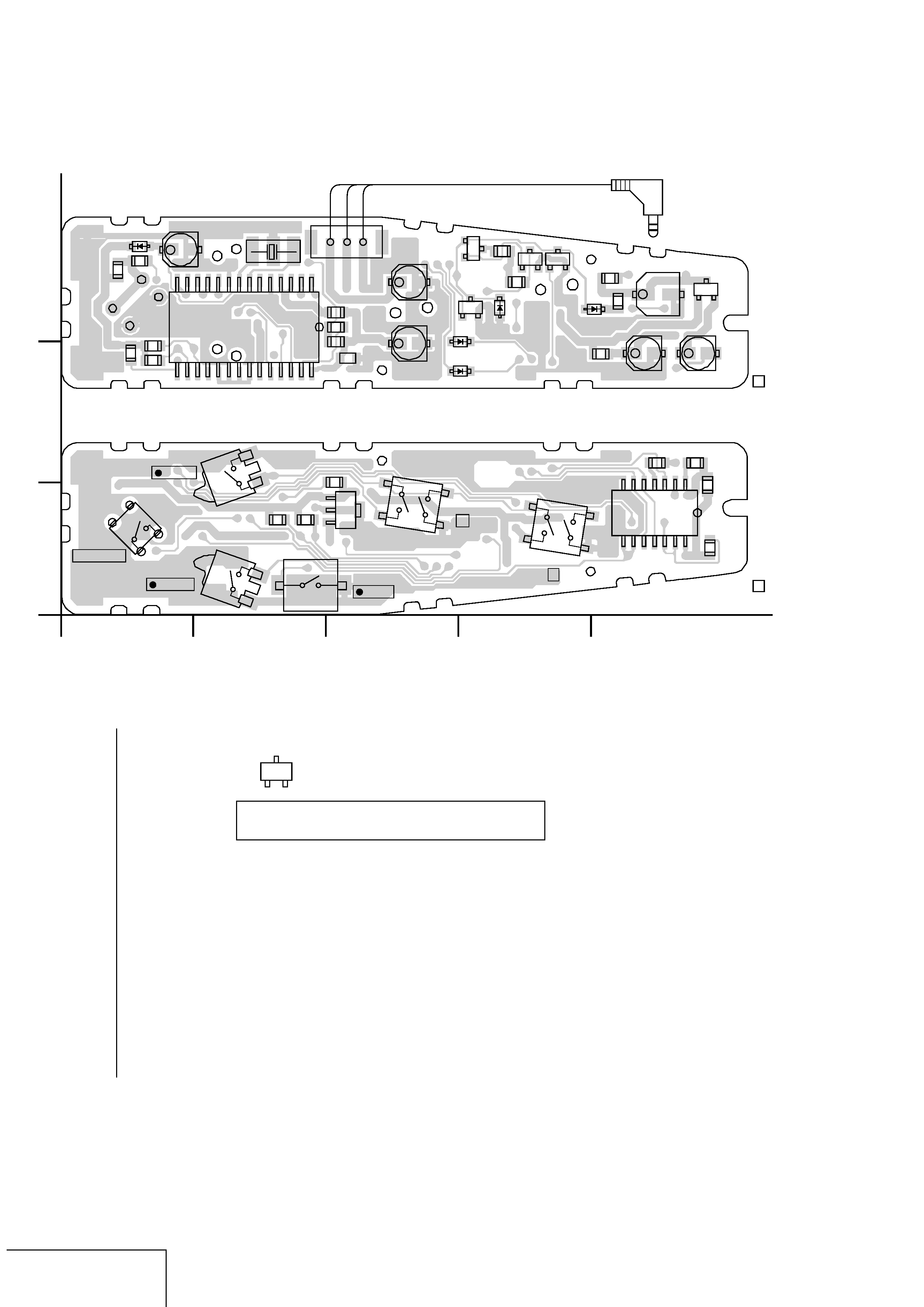
LS-49 BOARD
LANC CONTROL
LS-49
For printed wiring board
· Chip parts
Transistor
There are a few cases that the part printed on
this diagram isn't mounted in this model.
C
BE
LS-49 (LANC CONTROL) PRINTED WIRING BOARD
SPK-DVF3
B+
B+
B+
B+
B+
B+
B+
R015
100k
R013
100k
R014
10k
R016 100k
R017 100k
R019
100k
R018
100k
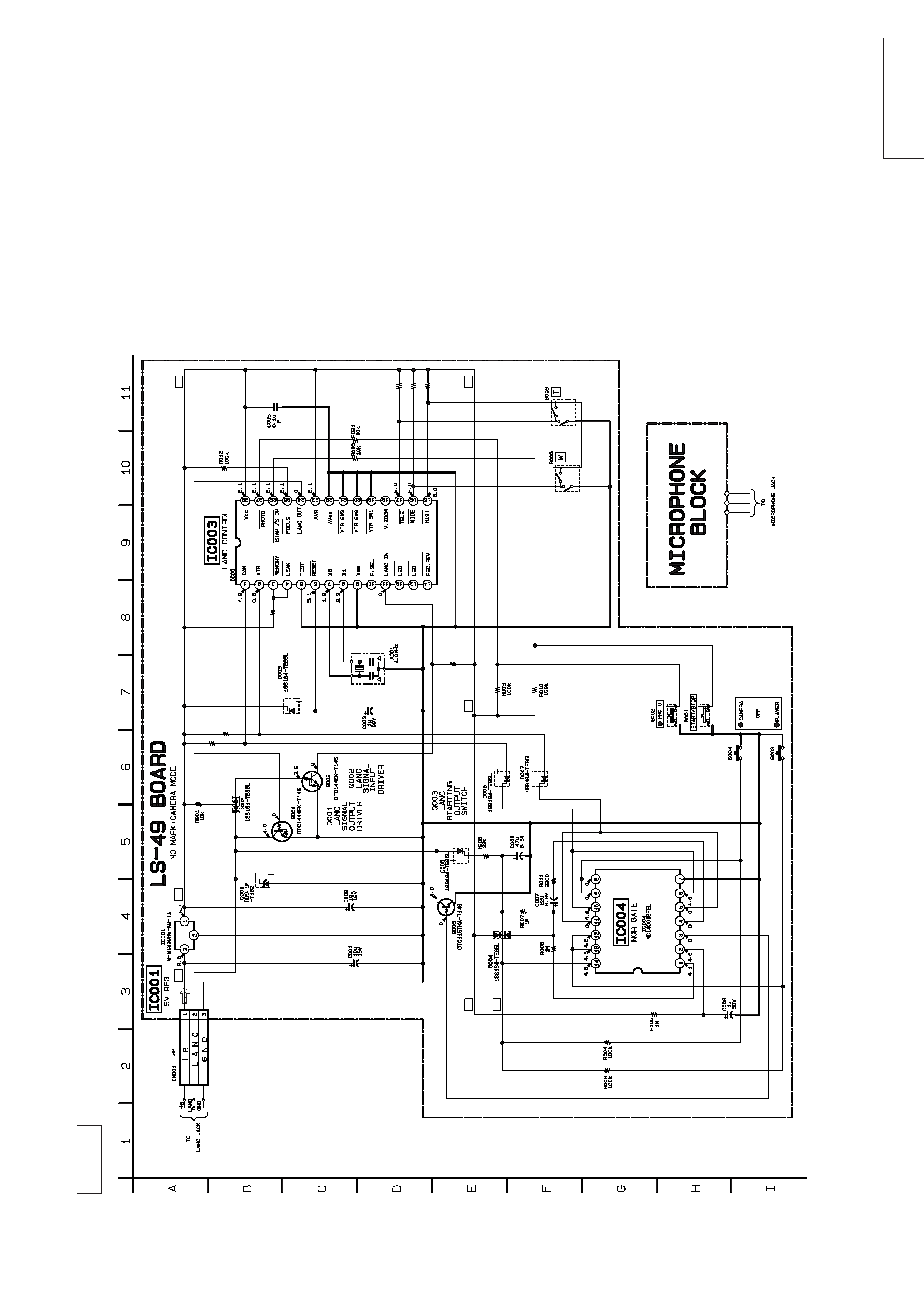
3 MB89191APF-G-266-BND
CAMCORDER
CAMCORDER
16
-- 5 --
-- 6 --
LANC CONTROL
LS-49
LS-49 (LANC CONTROL)
SPK-DVF3
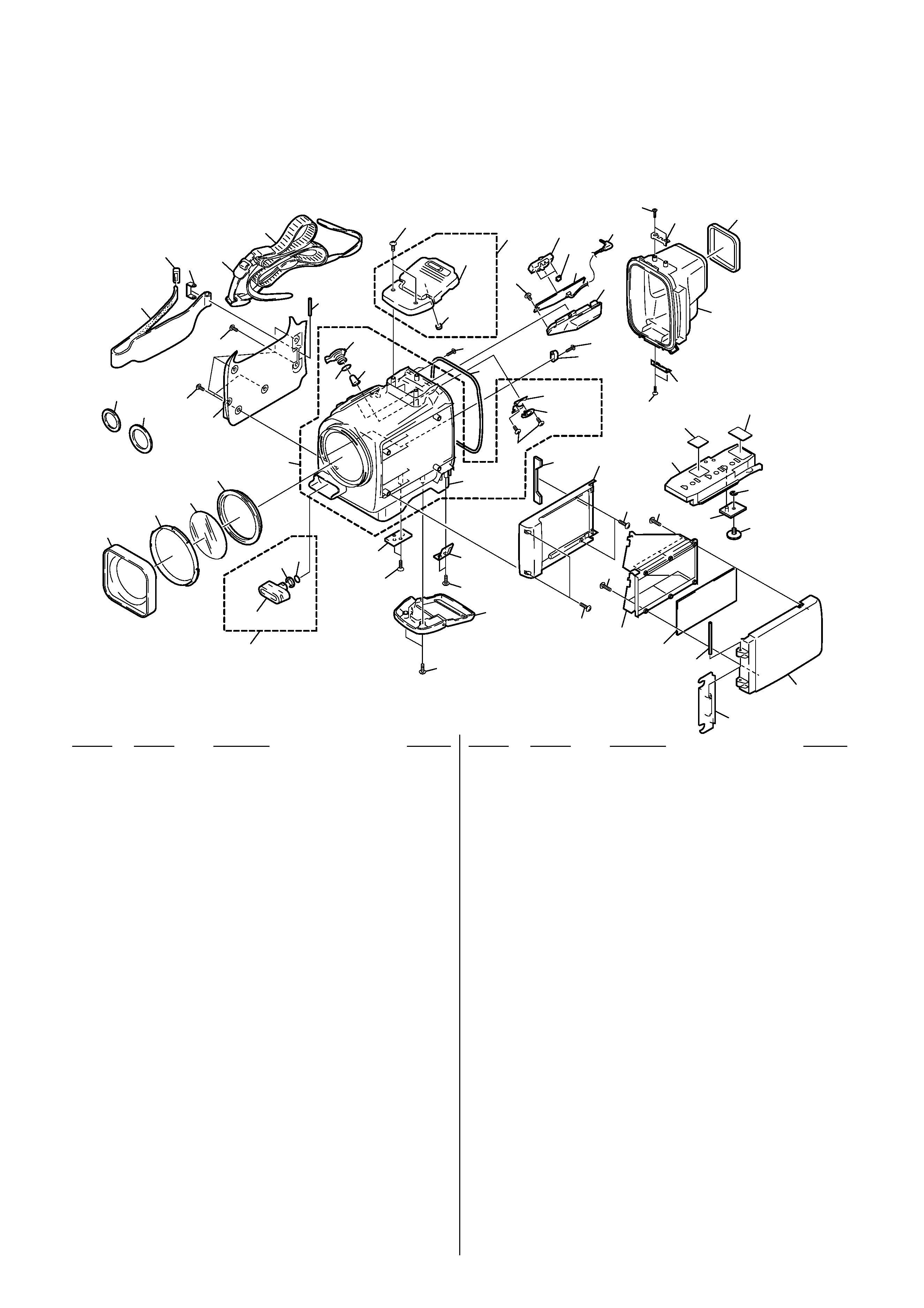
2-1. EXPLODED VIEWS
NOTE:
·
-XX, -X mean standardized parts, so they may
have some differences from the original one.
·
Items marked "*" are not stocked since they
are seldom required for routine service. Some
delay should be anticipated when ordering
these items.
SECTION 2
REPAIR PARTS LIST
1
2
3
4
5
6
7
47
21
10
58
58
52
11
46
13
14
15
18
56
19
55
20
20
22
23
24
54
25
26
27
28
9
29
30
42
33
53
53
34
8
58
36
37
38 39
not
supplied
not
supplied
not
supplied
not
supplied
40
41
32
43
12
45
49
44
51
50
48
57
57
31
not
supplied
16
17
58
35
58
1
3-976-866-01 COVER, LENS WINDOW
2
3-976-868-01 RETAINER, LENS WINDOW
3
3-976-867-01 WINDOW, LENS
4
3-976-869-01 PACKING, LENS WINDOW
5
X-3949-617-1 CASE ASSY, FRONT
6
3-960-765-01 RING, GRIP BELT
7
3-960-764-01 BELT, GRIP
8
3-952-054-01 BRAKET, SHOULDER
9
3-978-631-01 PLATE (LOWER), BUCKLE LOCK
10
3-976-870-01 COVER, GRIP
11
3-952-402-01 SHAFT, STOPPER, GRIP BELT
12
7-685-852-04 +BVTT 2X5 (S)
13
3-952-029-01 LEVER, STAND-BY
14
3-951-807-11 RING, O
* 15
3-952-030-01 PUSH BUTTON, REC
16
A-7007-374-A BUCKLE (UPPER) BLOCK ASSY
17
2-115-885-01 CAP, AIR PUNCHING
18
3-976-873-01 PACKING, CABINET
* 19
3-970-213-01 PLATE, SPRING
20
3-951-813-11 SCREW (2X6) (TYPE 2), +K
21
3-951-814-01 SCREW (2.6X10) (TYPE 2), +K
22
3-050-144-01 HOLDER, TW
23
3-979-245-01 BUTTON, T/W
24
A-7073-569-A LS-49 BOARD, COMPLETE
25
1-696-933-31 CORD, CONNECTION
* 26
3-960-763-11 LID, CONTROL BOX
27
3-978-629-01 PIN, MIRROR HINGE
28
3-976-834-01 PLATE (UPPER), BUCKLE LOCK
29
3-050-148-01 EYE CUP
30
3-050-147-01 CASE, REAR
31
3-976-848-01 BASE, MIRROR
32
3-979-464-01 BRACKET (B), SHOULDER BELT
33
3-976-846-01 HOOD, MIRROR
34
3-976-847-01 MIRROR
35
A-7007-375-A BUCKLE (LOWER) BLOCK ASSY
36
2-115-831-01 SCREW
37
A-6776-297-A MICROPHONE BLOCK ASSY
38
3-959-461-01 PACKING, MICROPHONE
39
3-959-422-01 RING (P10), O
40
3-953-086-01 BRACKET
41
3-941-465-01 BELT, STRAP
42
3-978-635-01 STOPPER, HOOD
43
3-061-059-01 RING (B) (M30), PREVENTION
* 44
3-970-217-01 SCREW, CAMERA FITTING
45
2-391-512-00 RING (5), RETAINING, E TYPE
46
3-978-527-01 SLIDER, MIRROR
47
3-978-526-01 COVER, MIRROR
48
3-050-146-01 BASE (A)
49
3-970-221-02 BASE, SLIDE
50
3-055-228-01 CUSHION (A) (SMALL), BASE
51
3-976-858-01 CUSHION (B), BASE
52
3-061-058-01 RING (B) (M37), PREVENTION
53
3-951-811-11 SCREW (2.6X7) (TYPE 2), +B
54
7-685-104-21 SCREW +P2X6 TYPE2
55
7-685-102-14 SCREW +P2X4 TYPE2 SLIT
56
7-685-533-14 SCREW +BTP 2.6X6 TYPE2 N-S
57
3-051-561-01 TAPPING +B2X6
58
3-051-562-01 TAPPING +B2.6 TYPE2
Ref. No.
Part No.
Description
Remarks
Ref. No.
Part No.
Description
Remarks
2-1-1. MAIN SECTION
-- 7 --
·
The mechanical parts with no reference
number in the exploded views are not
supplied.