SERVICE MANUAL
VIDEO CASSETTE RECORDER
SLV-KS1
RMT-V301
SPECIFICATIONS
US Model
Canadian Model
Mexican Model
· Refer to the SERVICE MANUAL of VHS MECHANICAL
ADJUSTMENTS VI for MECHANICAL ADJUSTMENTS.
(9-921-647-11)
S MECHANISM
System
Format
VHS NTSC standard
Video recording system
Rotary head helical scanning
FM system
Video heads
Double azimuth four heads
Video signal
NTSC color, EIA standards
General
Power requirements
120 V AC, 60 Hz
Power consumption
18 W (Mexican)
24 W (US, Canadian)
Operating temperature
5°C to 40°C (41°F to 104°F)
Dimensions
Approx. 355
× 96 × 285.5 mm
(w/h/d)
(Approx. 14
× 3 7/8 × 11 1/4
inches) including projecting
parts and controls
Mass
Approx. 3.6 kg (7lb 15oz)
Supplied accessories
Remote control (1)
Size AA (R6) batteries (2)
Audio/video cable (3-phono to 3-phono) (1)
Design and specifications are subject to change without
notice.
2
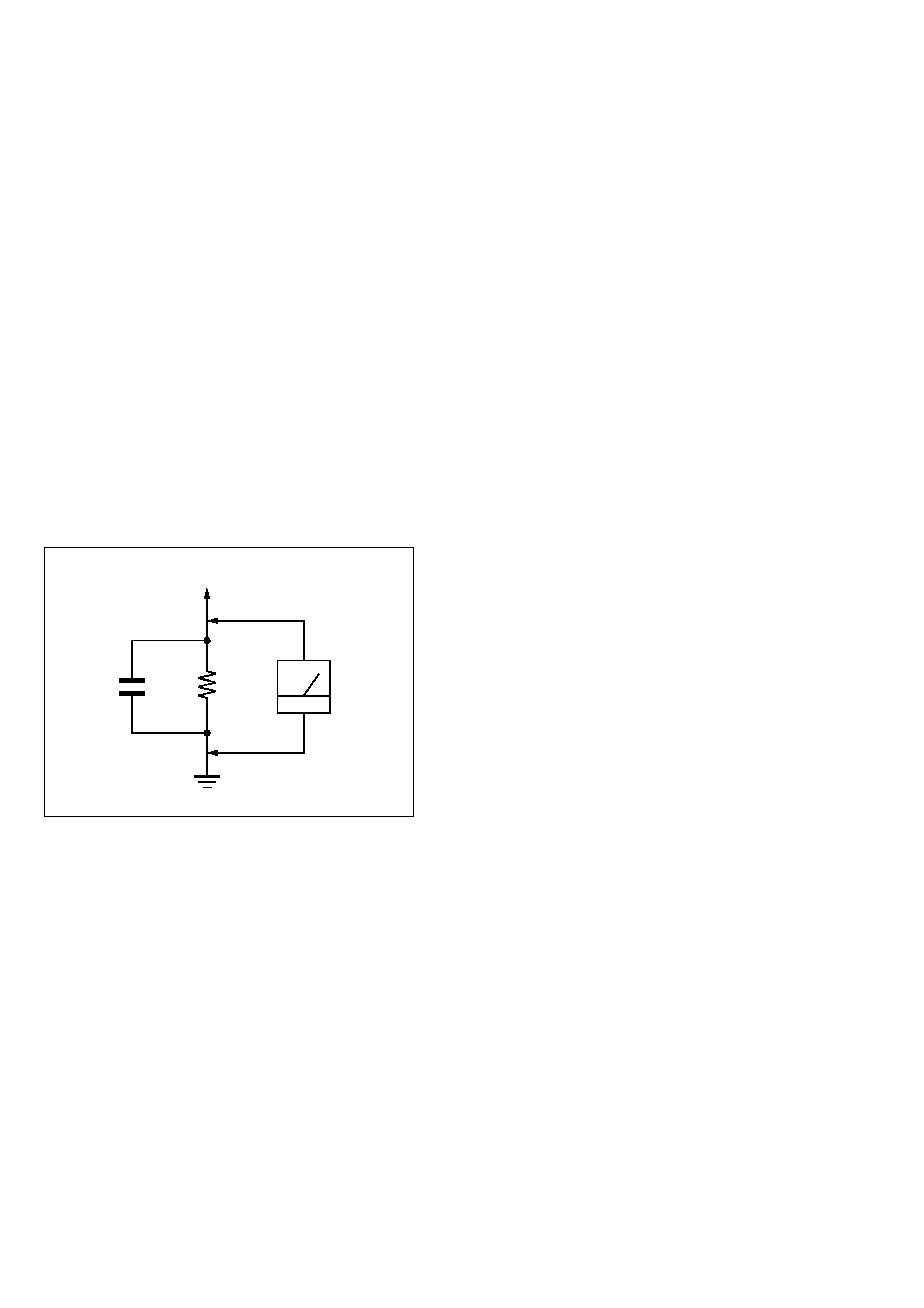
LEAKAGE TEST
The AC leakage from any exposed metal part to earth ground
and from all exposed metal parts to any exposed metal part having
a return to chassis, must not exceed 0.5 mA (500 microamperes).
Leakage current can be measured by any one of three methods.
1. A commercial leakage tester, such as the Simpson 229 or RCA
WT-540A. Follow the manufacturers' instructions to use these
instruments.
2. A battery-operated AC milliammeter. The Data Precision 245
digital multimeter is suitable for this job.
3. Measuring the voltage drop across a resistor by means of a
VOM or battery-operated AC voltmeter. The "limit" indica-
tion is 0.75V, so analog meters must have an accurate low-
voltage scale. The Simpson 250 and Sanwa SH-63Trd are ex-
amples of a passive VOM that is suitable. Nearly all battery
operated digital multimeters that have a 2V AC range are suit-
able. (See Fig. A)
Fig. A
Using AC voltmeter to check AC leakage
1.5 k
0.15
µF
AC
Voltmeter
(0.75 V)
To Exposed Metal
Parts on Set
Earth Ground
ATTENTION AU COMPOSANT AYANT RAPPORT
À LA SÉCURITÉ!
LES COMPOSANTS IDENTIFIÉS PAR UNE MARQUE 0
SUR LES DIAGRAMMES SCHÉMATIQUES ET LA LISTE
DES PIÈCES SONT CRITIQUES POUR LA SÉCURITÉ
DE FONCTIONNEMENT. NE REMPLACER CES COM-
POSANTS QUE PAR DES PIÈCES SONY DONT LES
NUMÉROS SONT DONNÉS DANS CE MANUEL OU
DANS LES SUPPLÉMENTS PUBLIÉS PAR SONY.
1. Check the area of your repair for unsoldered or poorly-sol-
dered connections. Check the entire board surface for solder
splashes and bridges.
2. Check the interboard wiring to ensure that no wires are
"pinched" or contact high-wattage resistors.
3. Look for unauthorized replacement parts, particularly transis-
tors, that were installed during a previous repair. Point them
out to the customer and recommend their replacement.
4. Look for parts which, though functioning, show obvious signs
of deterioration. Point them out to the customer and recom-
mend their replacement.
5. Check the line cord for cracks and abrasion. Recommend the
replacement of any such line cord to the customer.
6. Check the B+ voltage to see it is at the values specified.
7. Check the antenna terminals, metal trim, "metallized" knobs,
screws, and all other exposed metal parts for AC leakage.
Check leakage as described below.
SAFETY CHECK-OUT
After correcting the original service problem, perform the following
safety checks before releasing the set to the customer:
SAFETY-RELATED COMPONENT WARNING!!
COMPONENTS IDENTIFIED BY MARK 0 OR DOTTED
LINE WITH MARK 0 ON THE SCHEMATIC DIAGRAMS
AND IN THE PARTS LIST ARE CRITICAL TO SAFE
OPERATION. REPLACE THESE COMPONENTS WITH
SONY PARTS WHOSE PART NUMBERS APPEAR AS
SHOWN IN THIS MANUAL OR IN SUPPLEMENTS PUB-
LISHED BY SONY.

3
TABLE OF CONTENTS
Section
Title
Page
Section
Title
Page
SERVICE NOTE ...................................................................... 4
1.
GENERAL
Play Timer ...................................................................... 1-1
Cassette Door Lock (Safety Lock) ................................ 1-1
Recording and Tape Speed Buttons ............................. 1-1
Connections .................................................................. 1-2
2.
DISASSEMBLY
2-1.
Upper Case Removal .................................................... 2-1
2-2.
Front Panel Section Removal ....................................... 2-1
2-3.
Rear Panel (M) Removal .............................................. 2-1
2-4.
Mechanism Deck Removal ........................................... 2-1
2-5.
MA-370 Board Removal ................................................ 2-2
2-6.
Internal Views ................................................................ 2-3
2-7.
Circuit Boards Location ................................................. 2-4
3.
BLOCK DIAGRAMS
3-1.
Overall Block Diagram .................................................. 3-1
3-2.
Video Block Diagram ..................................................... 3-3
3-3.
Servo/System Control Block Diagram .......................... 3-5
3-4.
Audio Block Diagram ..................................................... 3-7
3-5.
Power Block Diagram .................................................... 3-9
4.
PRINTED WIRING BOARDS AND
SCHEMATIC DIAGRAMS
4-1.
Frame Schematic Diagram ........................................... 4-3
4-2.
Printed Wiring Boards and Schematic Diagrams ......... 4-5
MA-370 Printed Wiring Board ....................................... 4-5
MA-370 (Head Amp) Schematic Diagram .................... 4-7
MA-370 (Video, Audio) Schematic Diagram ................. 4-9
MA-370 (Servo/System Control)
Schematic Diagram ....................................................... 4-13
MA-370/QP-1 (Kids Sound) Printed Wiring Board
and Schematic Diagram ................................................ 4-17
MA-370 (Mode Control) Schematic Diagram ............... 4-19
MA-370 (Power Supply) Schematic Diagram ............... 4-21
5.
INTERFACE, IC PIN FUNCTION DESCRIPTION
5-1.
System Control-Video/RP Block Interface
(MA-370 BOARD IC160) ............................................... 5-1
5-2.
System Control-Servo Peripheral Circuit Interface
(MA-370 BOARD IC160) ............................................... 5-1
5-3.
System Control-Mechanism Block Interface
(MA-370 BOARD IC160) ............................................... 5-2
5-4.
System Control-System Control Peripheral
Circuit Interface (MA-370 BOARD IC160) .................... 5-3
5-5.
System Control-Audio Block Interface
(MA-370 BOARD IC160) ............................................... 5-3
5-6.
Servo/System Control Microprocessor Pin Function
(MA-370 BOARD IC160) ............................................... 5-4
6.
ADJUSTMENTS
6-1.
Mechanical Adjustments ............................................... 6-1
6-2.
Electrical Adjustments ................................................... 6-1
2-1.
Pre-Adjustment Preparations ........................................ 6-1
2-1-1. Instruments to be Used ............................................ 6-1
2-1-2. Connection ............................................................... 6-1
2-1-3. Set-up of Adjustment ................................................ 6-1
2-1-4. Alignment Tapes ....................................................... 6-1
2-1-5. Specified I/O Level and Impedance
input/output terminal ................................................ 6-1
2-1-6. Adjusting Sequence ................................................. 6-2
2-2.
Power Supply Adjustment ............................................. 6-2
2-2-1. Power Supply Check ................................................ 6-2
2-3.
Servo System Adjustment ............................................. 6-2
2-3-1. RF Switching Position Adjustment ........................... 6-2
2-4.
Audio System Adjustments ........................................... 6-3
2-4-1. Normal Audio System Adjustment ........................... 6-3
1.
ACE Head Adjustment .................................................. 6-3
2.
E-E Output Level Check ............................................... 6-3
3.
Frequency Response Check ......................................... 6-3
2-5.
Parts Arrangement Diagram for Adjustments ............... 6-4
7.
REPAIR PARTS LIST
7-1.
Exploded Views ............................................................. 7-1
7-1-1. Front Panel and Chassis Assembly ......................... 7-1
7-1-2. Mechanism Chassis Assembly (1) ........................... 7-2
7-1-3. Mechanism Chassis Assembly (2) ........................... 7-3
7-1-4. Mechanism Chassis Assembly (3) ........................... 7-4
7-2.
Electrical Parts List ........................................................ 7-5
4
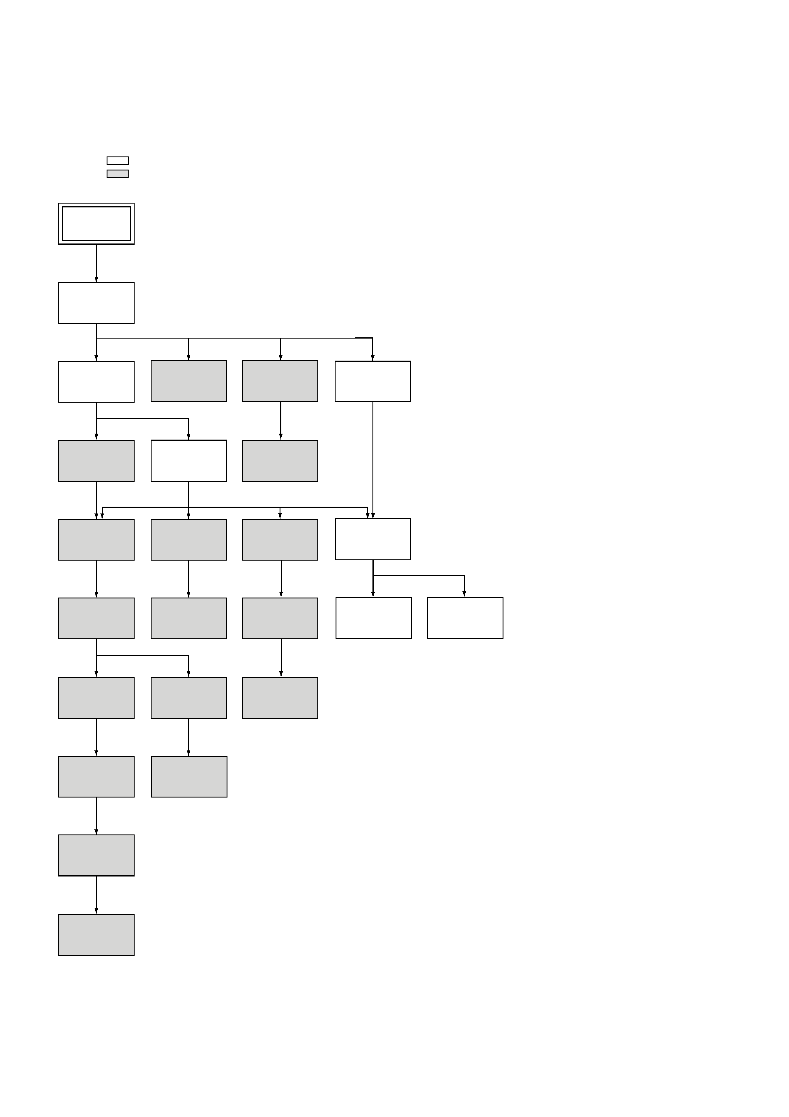
SERVICE NOTE
1. DISASSEMBLY
· This set can be disassembled in the order shown below.
Note: Pages in
indicated pages in the SERVICE MANUAL.
Pages in
indicated pages in the VHS MECHANICAL ADJUSTMENT MANUAL VI.
Set
Upper Case
(Page 2-1)
Front Panel
Section
(Page 2-1)
Pinch Press
Block Ass'y
(Page 14)
Ground Shaft
Ass'y
(Page 13)
Mechanism
Deck
(Page 2-1)
FL Complete
Ass'y
(Page 13)
Drum
Ass'y
(Page 13)
Rear Panel
(M)
(Page 2-1)
Rubber
Belt
(Page 15)
Rubber
Belt
(Page 15)
Slider
(Page 26)
Loading
Gear (T, S)
(Page 28)
Retainer
Plate
(Page 22)
Rubber
Belt
(Page 15)
Capstan
Motor
(Page 15)
FL Slider
Block Ass'y
(Page 22)
Pully Gear
Ass'y
(Page 29)
Cam Motor
Retainer
(Page 31)
Cam Gear
(Page 23)
Cam Motor
(Page 31)
Reel Direct
Ass'y
(Page 30)
MA-370
Board
(Page 2-2)
Rotary
Switch
(Page 2-1)
Tuner
Unit
1-1
SECTION 1
GENERAL
This section is extracted from instruc-
tion manual. (3-062-072-11)
SLV-KS1
Press
N then x
N then X
M then x
N then m
m then N
M then N
x then m
Press
M then X
X then N
N then M
M then m
x then N
m then X
X then M
m then M
X then x
x then M
x then X
m then x
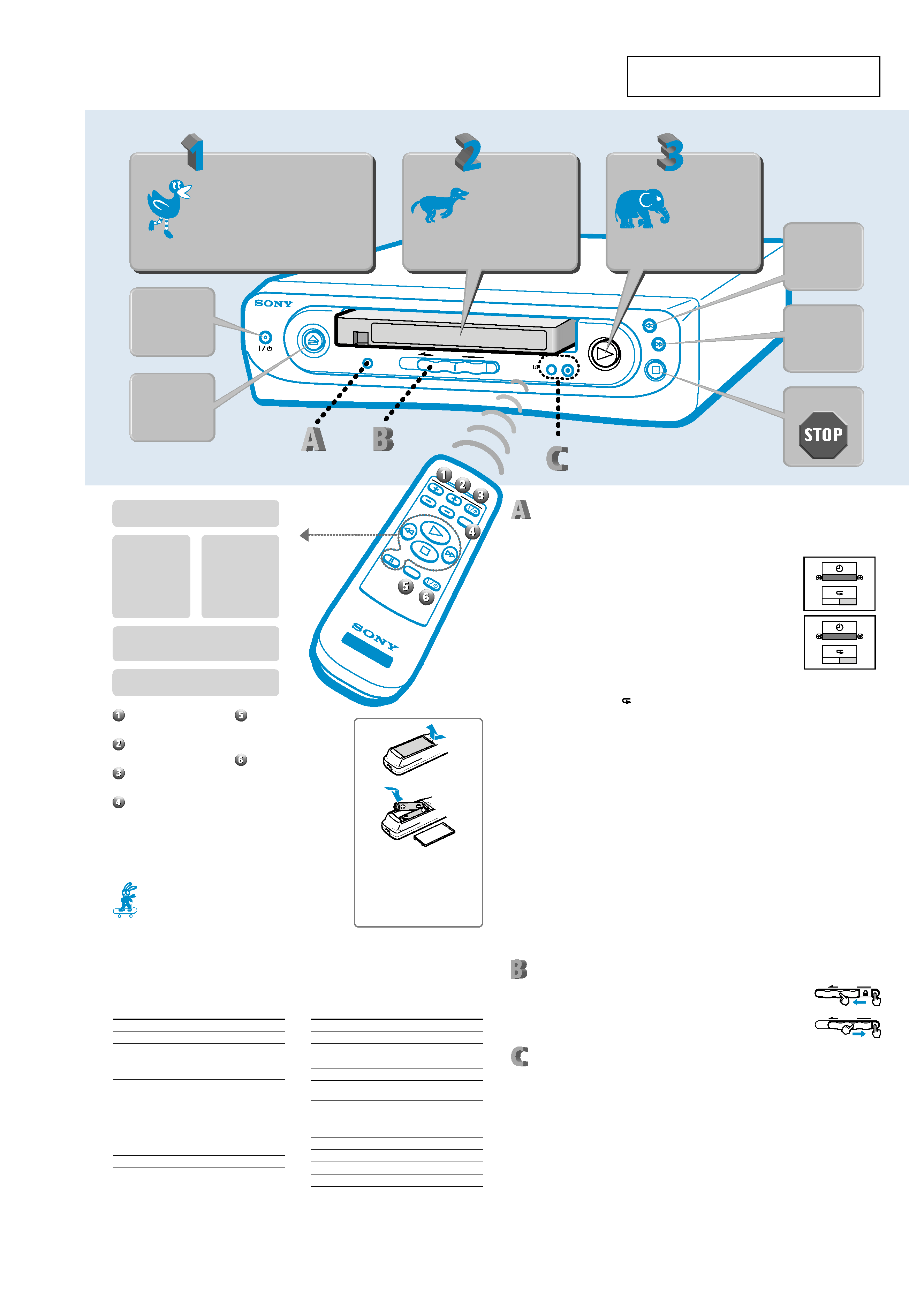
PLAY TIMER
SET UP
POWER
PUSH
DOOR LOCK
SP/EP
REC
Manufacturer
General Electric/RCA/Sears
Gold Star/MGA/Mitsubishi
Hitachi
JVC
Magnavox/Philips/Sylvania/
Teknika
Marantz/MGA/Mitsubishi
Panasonic
Pioneer
Quasar/Sharp
Radio Shack/Sharp
Sears/Toshiba
Zenith
m REW (rewind)
button
Press x STOP and
then this button to
rewind a tape. To
watch the picture in
fast motion, press this
button while the tape
is playing.
Manufacturer
Sony
Akai/AOC/Emerson/Gold Star/
J.C.Penney/Marantz/MGA/
Mitsubishi/NEC/Philco/RCA/
Wards
Centurion/Curtis-Mathes/
Daytron/J.C.Penney/Magnavox/
MGA/Mitsubishi/NEC/Sampo/
Scott/Sylvania/Wards/York
Coronado/Emerson/Gold Star/
Hitachi/KMC/Magnavox/Philco/
Portland/Sharp/Teknika/Wards
Emerson/Radio Shack/Teknika
Fisher/Sanyo/Sears
General Electric/Panasonic/Quasar
OFF
O N
OFF
90MIN
O N
OFF
Program your Remote Commander remote control!
You can set your remote control to control the power, channel, volume, and video input of your TV.
First find the manufacturer's name of your TV. Then, while holding down the TV power button
(button TV I/1) on the remote control, press the operation buttons in the order shown in the chart.
N PLAY button
Press this button to play a tape.
M FF (fast
forward) button
Press x STOP and
then this button to fast
forward a tape. To
watch the picture in
fast motion, press this
button while the tape
is playing.
x STOP button
Press this button to stop the tape when it is
playing, rewinding, fast forwarding, or recording.
VOL +/ buttons:
These buttons change the
volume on your TV.
CH +/ buttons:
These buttons change the
channels on your TV.
TV I/1 (power) button:
Use this button to turn your TV
on and off.
TV/VIDEO button:
This button switches your TV
between regular TV programs
and the video input.
You must first program your remote
control to use the buttons 1 through
4 above (see below).
m
PUSH
DOOR LOCK
DOOR LOCK
PUSH
DISPLAY button:
This button will turn on or off
the animations that appear
when you fast forward or
rewind a tape.
POWER /1 button:
Although this button turns the
VCR on and off, the VCR will
turn on automatically when
you insert a tape or press the
N PLAY, M FF, m REW,
z REC, or PLAY TIMER SET
UP buttons. The VCR will turn
off automatically if no buttons
are pressed for more than five
minutes after the tape is
stopped or ejected.
TV
PAUSE
DISPLA
Y
STO
P
PL
AY
FF
REW
TV/VIDEO
CH
VO
L
PO
WER
V
ID
E
O
Play Timer
The Play Timer function allows you to control the amount of time your child watches a video. For
example, let's say you want your child to watch a cartoon for 90 minutes.
1 Press the PLAY TIMER SET UP button for more than five seconds.
The set up screen appears on your TV.
2 Press the M (fast forward) or m (rewind) buttons to select 90
minutes.
The time will change in thirty minute increments. If you continue to
press either the M (fast forward) or m (rewind) button, the playing
time will scroll as follows:
OFF y 30 y 60 y 90 y 120 y 150 y 180 y OFF
3 After you select the playing time, press the PLAY TIMER SET UP button.
The ON/OFF row of the
(repeat) option is highlighted.
4 Press the M (fast forward) or m (rewind) button to set the repeat function ON or OFF.
If you select ON and the tape reaches the end before the timer is up, it will automatically rewind
and play the tape from the beginning.
5 Press the PLAY TIMER SET UP button again.
The set up screen will disappear and the timer will start. Follow the steps above to start
watching a video.
When your child is watching a video, all of the buttons (except the z REC (record) button) will
work. After the set playing time has elapsed, the power will turn off and all of the buttons will be
locked for one hour. If you press a button while the VCR is locked, the light on the POWER I/1
button will flash for five seconds.
To check the remaining time
Press the PLAY TIMER SET UP button once. The remaining time will appear on your TV screen.
When five minutes are left, the remaining time will automatically appear on your TV screen for 30
seconds.
To cancel the Play Timer
Press the PLAY TIMER SET UP button for more than five seconds. When the set up screen appears
on your TV, use the M (fast forward) or m (rewind) buttons to set the timer to OFF.
Notes
· As soon as you complete step 5 above, the timer will start to run even if you turn off the VCR. This means that the VCR
may enter the lock mode while the power is off, or that when you turn the VCR back on, the Play Timer will return to
the last setting you made. Follow the explanations above to change or cancel the Play Timer.
· The repeat function will rewind the tape no more than five times, regardless of the tape length or timer setting.
Cassette Door Lock (Safety Lock)
You can lock the cassette door to prevent your child from inserting or ejecting
cassette tapes. To lock the door, press down the PUSH button and move the
DOOR LOCK slide to the left until it clicks in place.
To unlock the door, press down the PUSH button and move the DOOR LOCK
slide to the right.
Recording and Tape Speed Buttons
You can use this VCR to record images input through the LINE IN jacks. For example, let's say you
want to record images of your child that you took with your video camera.
1 Press the SP/EP button to set the tape speed.
EP (Extended Play) provides recording time three times as long as SP (Standard Play).
However, SP produces better picture and audio quality.
2 Connect your video camera's LINE OUT jacks to the LINE IN jacks on the back of this
VCR, and insert a blank tape with its safety tab intact into this VCR. (If you are recording
a program on your TV, be sure to disconnect the VCR's LINE OUT jacks from your TV's
LINE IN jack and set the TV's TV/VIDEO button to TV.)
3 Press the z REC (record) button on this VCR.
4 Start playing the tape in your video camera.
The REC mark and tape speed (EP or SP) appear on your TV screen. To stop recording,
press x STOP.
Note
· The z REC button will not function when the Play Timer is activated. Cancel the Play Timer before you make a
recording.
Insert your
tape here
Step
Turn on your TV
and press your TV's
TV/VIDEO* button
*
The name of this button may be different
on your TV.
Step
Step
Press to
play!
Press to
rewind
Press to
fast
forward
Press to
Press to
turn ON/
OFF
Press to
eject
X PAUSE button
Press this button to momentarily stop the tape.
Inserting the batteries
Insert two size AA (R6) batteries by
matching the + and on the batteries
to the diagram inside the battery
compartment.
Insert the negative () end first, then
push in and down until the positive
(+) end clicks into place.
A playful animation will appear whenever you
rewind, fast forward, or insert a tape.