AiVt CHASSIS
Design and specifications are subject to change without notice.
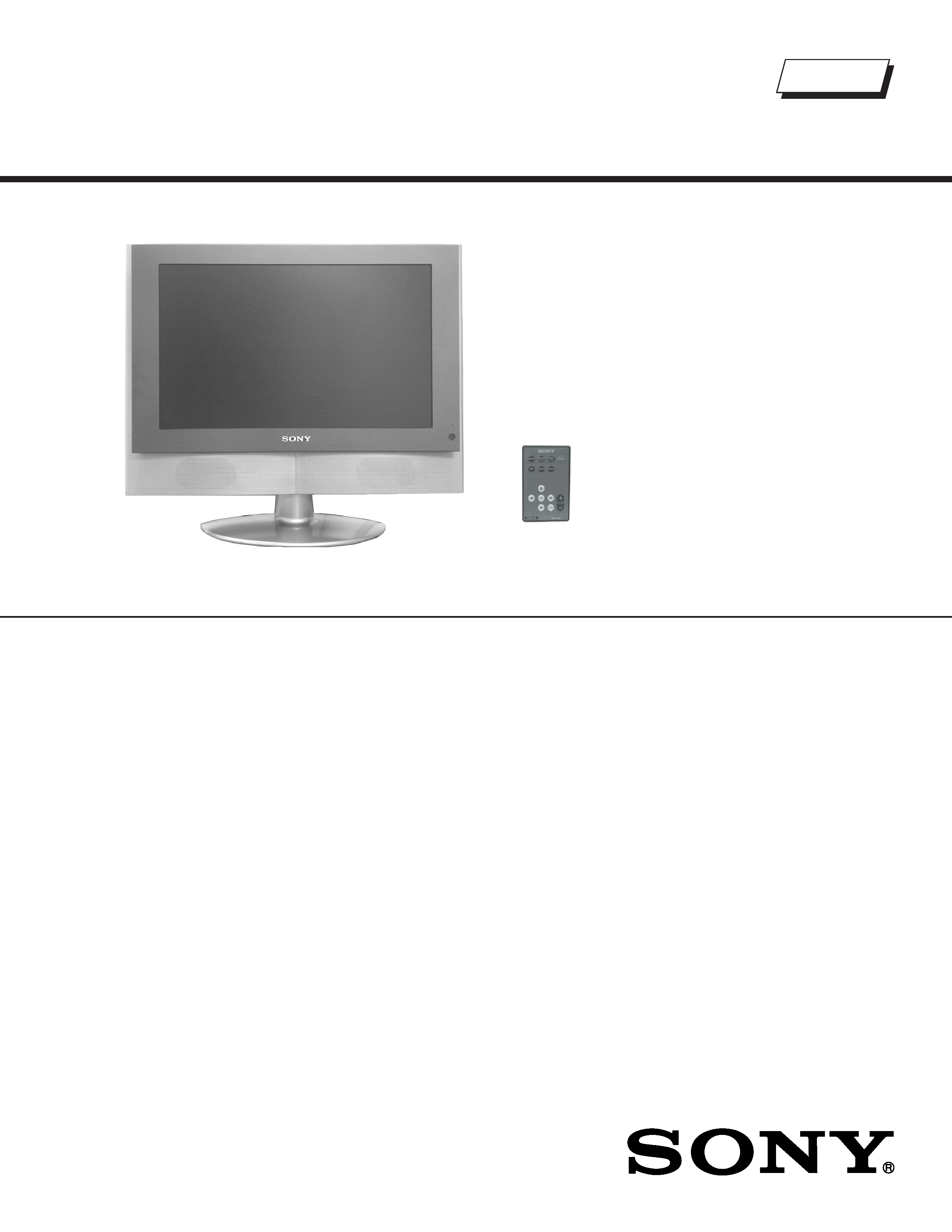
TFT LCD COLOR COMPUTER DISPLAY
US/Canada Model
9-978-990-02
SERVICE MANUAL
SDM-V72W
ORIGINAL MANUAL ISSUE DATE: 9/2002
ALL REVISIONS AND UPDATES TO THE ORIGINAL MANUAL ARE APPENDED TO THE END OF THE PDF FILE.
REVISION DATE
REVISION TYPE
SUBJECT
9/2002
No revisions or updates are applicable at this time.
10/2002
Correction - 1
Replaced Timing Specification (Pg. 5 & 5A)
IC1006, IC5002 P/N's Corrected on B Board in Electrical Parts List
HISTORY INFORMATION FOR THE FOLLOWING MANUAL:
AiVt CHASSIS
Design and specifications are subject to change without notice.
TFT LCD COLOR COMPUTER DISPLAY
US/Canada Model
9-978-990-02
SERVICE MANUAL
SDM-V72W
LCD Panel
Panel type: a-Si TFT Active Matrix
Video image area
171/10 inches
Resolution
Maximum
Horizontal: 1280 dots
Vertical: 768 lines
Input signal
RGB Operating Frequency
Horizontal 28-70 kHz
Vertical
45-85 Hz
Pixel clock 94.5 MHz max
PC Input signal levels
Analog RGB Video Signal
0.7 Vp-p, 75 ohms, positive
Sync signal TTL Level, 2.2k ohms
Positive or Negative
(Separate Horizontal and Vertical, or
Composite Sync)
0.3 Vp-p, 75 ohms, negative
(Sync on Green)
Component Video IN 2/RGB IN
Y
1 Vp-p, 75 ohms, 0.3V, negative sync
Pb
0.7 Vp-p, 75 ohms
Pr
0.7 Vp-p, 75 ohms
Video IN
S-Video In (4-pin mini DIN)
Y
1 Vp-p, 75 ohms unbalanced,
negative sync
C
0.286 Vp-p, 75 ohms
Video (phone jack)
1 Vp-p 75 ohms unbalanced,
negative sync
Audio Output
Speaker output: 3W x 2
Headphone jack: Stereo minijack
Impedance 16-48 ohms acceptable
Power Consumption
49 W Max
AC input voltage/current 100 to 240V, 50/60 Hz, Max. 0.9-0.5A
Dimensions
With Stand 472 x 405 x 184 mm (w/h/d)
(181/2 x 153/4 x 81/6 inches)
Without
472 x 348 x 73 mm (w/h/d)
Stand
(181/2 x 13 7/12 x 2 3/4 inches)
Mass
With Stand Approx. 5.9 kg (13 lbs)
Without
Approx. 5.1 kg (11.2 lbs)
Stand
Plug and Play
DDC2B
SPECIFICATIONS
Self Diagnosis
Supported model
RM-V72W

-- 3 --
SDM-V72W
TABLE OF CONTENTS
POWER MANAGEMENT.................................................................................................4
SELF DIAGNOSIS FUNCTION........................................................................................4
TIMING SPECIFICATION ................................................................................................5
WARNINGS AND CAUTIONS..........................................................................................6
SAFETY CHECK-OUT .....................................................................................................7
SECTION 1: DISASSEMBLY
1-1. Rear Panel Removal ...............................................................................................8
1-2. Rear Cover Assembly Removal...............................................................................8
1-3. H2 Board Removal ..................................................................................................9
1-4. D1 Board Removal ..................................................................................................9
1-5. A and B Board Removal ........................................................................................10
1-6. LCD Panel Removal..............................................................................................10
1-7. H3 Board Removal ................................................................................................11
1-8. H1 Board Removal ................................................................................................11
SECTION 2: DIAGRAMS
2-1. Circuit Boards Location .........................................................................................12
2-2. Printed Wiring Board and Schematic Diagram Information ..................................12
2-3. Block Diagrams .....................................................................................................13
2-4. Schematic Diagrams and Supporting Information.................................................14
D1 Board Schematic Diagram...............................................................................14
A Board Schematic Diagram (1 of 3).....................................................................16
A Board Schematic Diagram (2 of 3).....................................................................17
A Board Schematic Diagram (3 of 3).....................................................................18
H1 Board Schematic Diagram...............................................................................20
H2 Board Schematic Diagram...............................................................................20
H3 Board Schematic Diagram...............................................................................21
B Board Schematic Diagram (1 of 6).....................................................................22
B Board Schematic Diagram (2 of 6).....................................................................23
B Board Schematic Diagram (3 of 6).....................................................................24
B Board Schematic Diagram (4 of 6).....................................................................25
B Board Schematic Diagram (5 of 6).....................................................................26
B Board Schematic Diagram (6 of 6).....................................................................27
2-5. Semiconductors.....................................................................................................29
SECTION 3: EXPLODED VIEWS
3-1. Picture Tube ..........................................................................................................30
3-2. Packing Materials ..................................................................................................31
SECTION 4: ELECTRICAL PARTS LIST.............................................................................32
SECTION TITLE
PAGE
-- 4 --
SDM-V72W
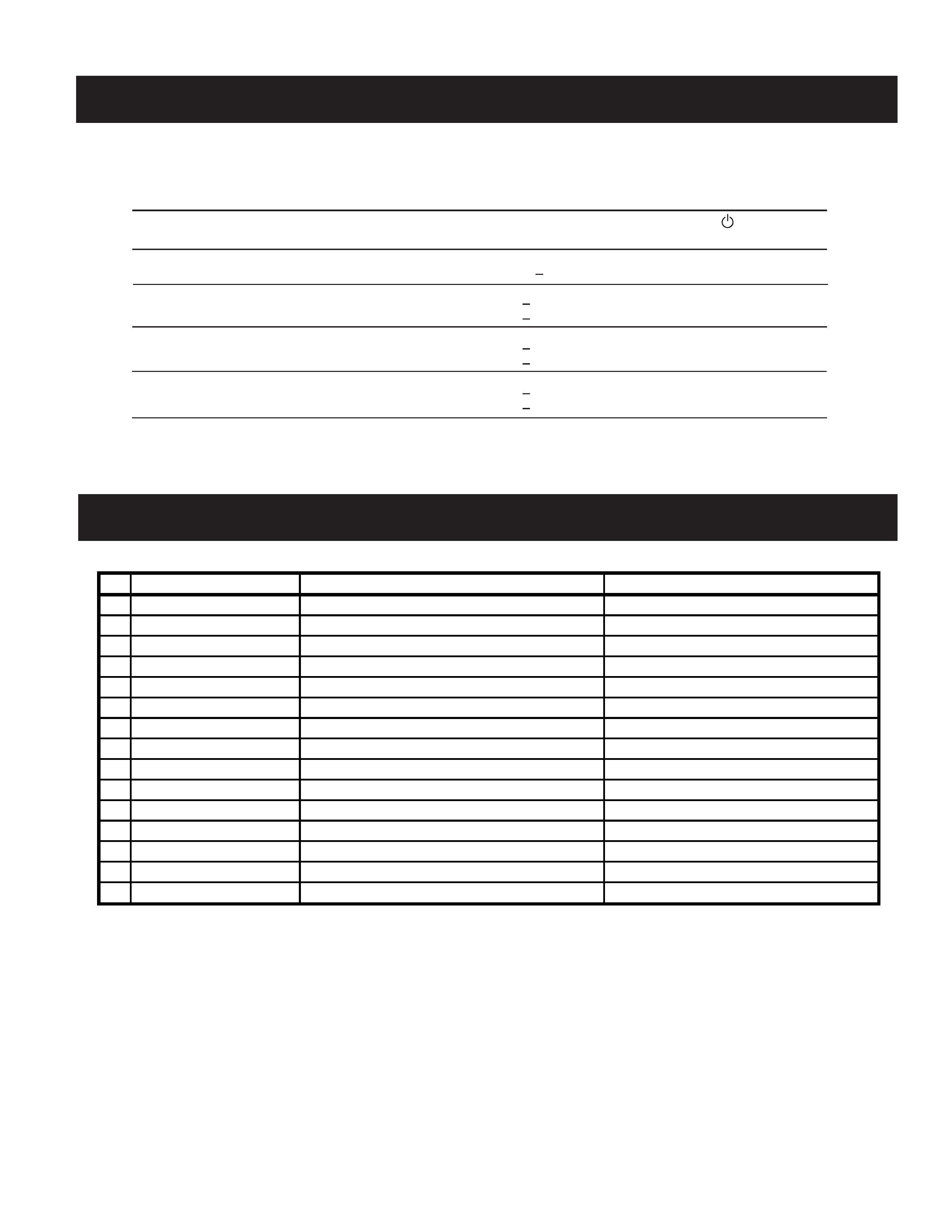
POWER MANAGEMENT
The power saving mode complies with the VESA Display Power Management Signaling standard. Each state of power management shall be
activated by the host computer terminating the appropriate sync signals. Blanking the video must precede termination of the sync signals. The
elapsed time counter shall also be controlled by the host computer. Reactivation of the monitor shall be accomplished from the host computer by
re-establishing the normal sync signal.
SELF DIAGNOSIS FUNCTION
If a failure occurs, the power LED indicator will flash a set number of times to indicate the possible cause of the problem.
Model Information: Press and hold the menu button for more than 5 seconds while inputing a signal.
Power consumption
Screen
Horizontal
Vertical
Power
Recovery time
Power LED
mode
(video) sync signal sync signal consumption
Indicator
1
Power On
active
yes
yes
< 49 W
--
Green
2
Standyby/Active-off
blank
no*
no*
< 3 (max) W
Approx. 10 sec.
Amber
< 2 (typ) W
3
Remote Off
--
--
--
< 3 (max) W
Red
< 2 (typ) W
4
Power Off
--
--
--
< 3 (max) W
Off
< 1 (max) W
In this mode, the signal will appear in one of three ways:
- The Horizontal Sync signal alone off
- The Vertical Sync signal alone off
- Both signals off
-- 5 --
SDM-V72W
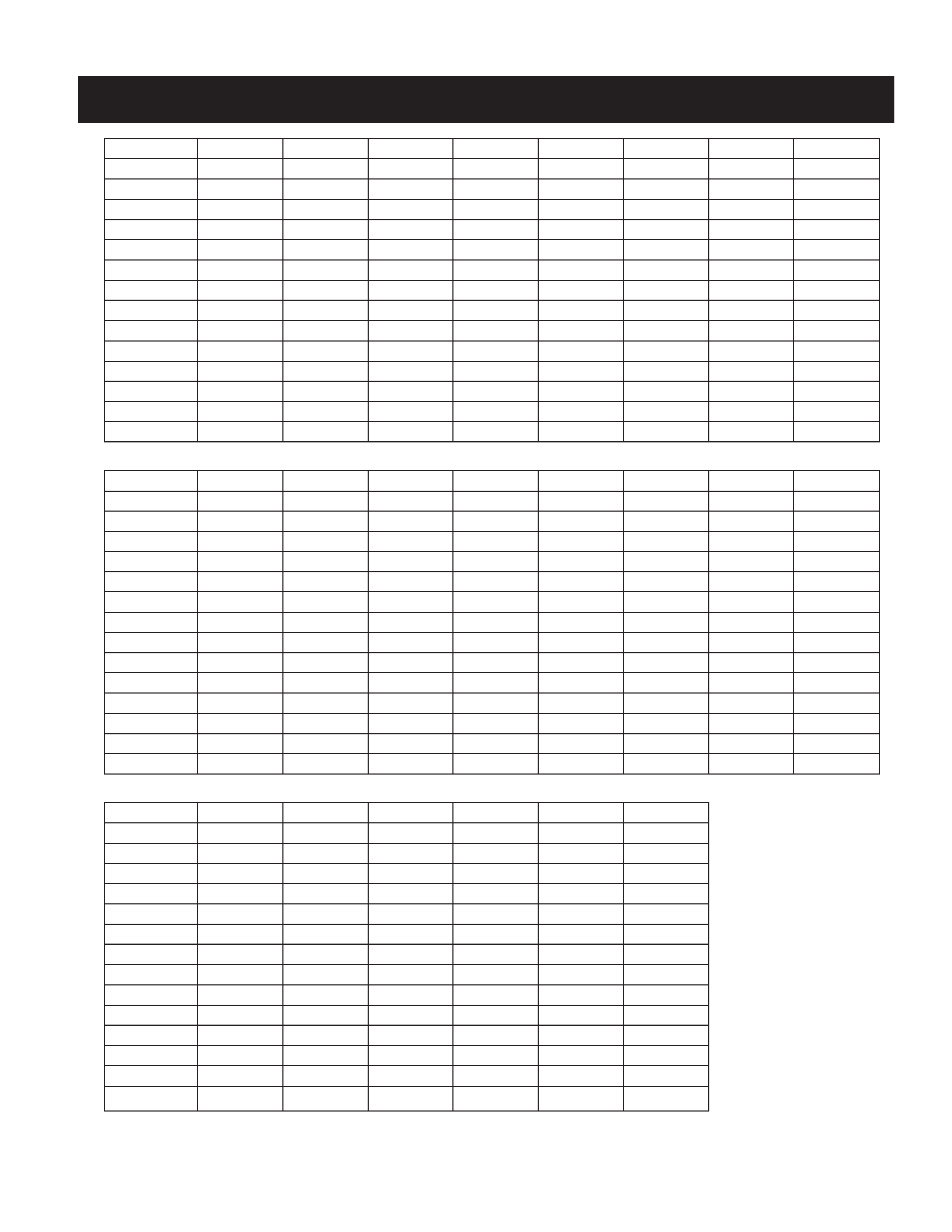
TIMING SPECIFICATION
PRESET MODE
MODE 1
MODE 2
MODE 3
MODE 4
MODE 5
MODE 6
MODE 7
MODE 8
SIGNAL MODE
VESA 60Hz
MAC 13"
VESA 75Hz
VESA 85Hz
VESA 70Hz VESA 60Hz
VESA 75Hz
VESA 85Hz
RESOLUTION
640 X 480
640 X 480
640 X 480
640 X 480
720 X 400
800 X 600
800 X 600
800 X 600
DOT CLOCK
25.175 MHz
30.240 MHz
31.500 MHz
36.000 MHz
28.350 MHz
40.000 MHz
49.500 MHz
56.250 MHz
HORIZONTAL
usec
usec
usec
usec
usec
usec
usec
usec
H. TOATL
31.778
28.571
26.667
23.111
31.746
26.400
21.333
18.631
H. SYNC
3.813
2.116
2.032
1.556
2.540
3.200
1.616
1.138
H. BP
1.907
3.175
3.810
2.222
3.175
2.200
3.232
2.702
H. ACTIV
25.422
21.164
20.317
17.778
25.397
20.000
16.162
14.222
VERTICAL
msec
msec
msec
msec
msec
msec
msec
msec
V. TOTAL
16.683
15.000
13.333
11.764
14.254
16.579
13.333
11.756
V. SYNC
0.064
0.086
0.080
0.069
0.095
0.106
0.064
0.056
V. BP
1.049
1.114
0.427
0.578
1.079
0.607
0.448
0.503
V. ACTIV
15.253
13.714
12.800
11.093
12.698
15.840
12.800
11.179
H/V POLARITY
N/N
N/N
N/N
N/N
N/P
P/P
P/P
P/P
PRESET MODE
MODE 9
MODE 10
MODE 11
MODE 12
MODE 13
MODE 14
MODE 15
MODE 16
SIGNAL MODE
PMAC 16"
VESA 60Hz
VESA 70Hz
VESA 75Hz
VESA 85Hz
PMAC 19"
MAC
WS
RESOLUTION
832 X 624
1024 X 768
1024 X 768
1024 X 768
1024 X 768
1024 X 768
1152 X 870
1152 X 900
DOT CLOCK
57.285 MHz
65.000 MHz
75.000 MHz
78.750 MHz
94.500 MHz
80.000 MHz
100.000MHz
92.940 MHz
HORIZONTAL
usec
usec
usec
usec
usec
usec
usec
usec
H. TOATL
20.110
20.677
17.707
16.660
14.561
16.600
14.560
16.182
H. SYNC
1.117
2.092
1.813
1.219
1.016
1.200
1.280
1.377
H. BP
3.910
2.462
1.920
2.235
2.201
2.200
1.440
2.087
H. ACTIV
14.524
15.754
13.653
13.003
10.836
12.800
11.520
12.395
VERTICAL
msec
msec
msec
msec
msec
msec
msec
msec
V. TOTAL
13.413
16.666
14.272
13.328
11.765
13.346
13.322
15.163
V. SYNC
0.060
0.124
0.106
0.050
0.044
0.050
0.044
0.065
V. BP
0.744
0.600
0.513
0.466
0.524
0.498
0.568
0.502
V. ACTIV
12.549
15.880
13.599
12.795
11.183
12.749
12.667
14.564
H/V POLARITY
N/N
N/N
N/N
P/P
P/P
N/N
N/N
N/N
PRESET MODE
MODE 17
MODE 18
MODE 19
MODE 20
MODE 21
MODE 22
SIGNAL MODE
WS
VESA 60Hz
VESA 85Hz
VESA 60Hz
VESA 75Hz
VESA 85Hz
RESOLUTION
1152 X 900
1280 X 960
1280 X 960
1280 X 1024 1280 X 1024 1280 X 1024
DOT CLOCK
105.590 MHz 108.000 MHz 148.500 MHz
108.000
135.000
157.500
HORIZONTAL
usec
usec
usec
usec
usec
usec
H. TOATL
13.941
16.667
11.636
15.630
12.504
10.971
H. SYNC
0.909
1.037
1.077
1.037
1.067
1.016
H. BP
1.970
2.889
1.508
2.296
1.837
1.422
H. ACTIV
10.910
11.852
8.620
11.852
9.481
8.127
VERTICAL
msec
msec
msec
msec
msec
msec
V. TOTAL
13.146
16.667
11.764
16.661
13.329
11.761
V. SYNC
0.112
0.050
0.035
0.047
0.038
0.033
V. BP
0.460
0.600
0.547
0.594
0.475
0.483
V. ACTIV
12.547
16.000
11.171
16.005
12.804
11.235
H/V POLARITY
N/N
P/P
P/P
P/P
P/P
P/P