Registered No.
Reproduction Prohibited
SERIES
3rd Edition
Japan Model
SCPH-9000
US/Canada Model
SCPH-9001
Australia Model
SCPH-9002A
UK Model
SCPH-9002B
AEP Model
SCPH-9002C
Asia Model
SCPH-9003
SCPH-9000
SCPH-9000 SERIES
Sony Computer Entertainment Inc.
Customer Service Dept.
1999. 5 Printed in Japan © 9-927-069-03
Sony Computer Entertainmant Europe

-- 1 --
SCPH-9000 SERIES
Reproduction Prohibited
TABLE OF CONTENTS
1. SPECIFICATIONS ..................................................................2
2. EXPLODED VIEW ..................................................................3
3. ADJUSTMENT
3-1.Adjustment and Check Specification ............................................. 4
4. NOTICE .......................................................................................4
5. BLOCK DIAGRAMS ..............................................................5
6. PRINTED WIRING BOARDS
AND SCHEMATIC DIAGRAMS
· Printed Wiring Board [PU-23 Board (-11/-21/-31/-41/-51)] ........... 8
· Schematic Diagram [PU-23 Board (1/4) (-11/-21/-31/-41/-51)] ..... 9
· Schematic Diagram [PU-23 Board (2/4) (-11/-21/-31/-41/-51)] ... 10
· Schematic Diagram [PU-23 Board (3/4) (-11/-21/-31/-41/-51)] ... 11
· Schematic Diagram [PU-23 Board (4/4) (-11/-21/-31/-41/-51)] ... 12
· Power Block (1-468-366-11) ......................................................... 14
· Power Block (1-468-365-11) ......................................................... 15
· Power Block (1-468-303-13) ......................................................... 16
· Power Block (1-468-243-11) ......................................................... 17
7. ELECTRICAL PARTS LIST
· PU-23 Board .................................................................................. 18
· Power Block ................................................................................... 23
Notice
Manual copylight 1999 by Sony Computer Entertainment Inc. All rights.
Reproduction without the expressed written permission of Sony
Computer Entertainment Inc. is strictly prohibited.Commercial use or
rental prohibited.
Revisions
Design and specifications are subject to change with out notice.
SCEI. Customer Service Dept. Service web site PS SERVICE PLAZA
(http:// svc. scei. co. jp) should be used together with this manual.
Attention
Ordering replacement components.
SCEI. Customer Service Dept. Parts-Group is received PlayStation-
repair parts order. When you want to get them. Please accesses to
this E-mail address. (sec_parts@ hq. scei. sony. co. jp)
SCPH-9000 SERIES
-- 2 --
Reproduction Prohibited
SECTION 1
SPECIFICATIONS
General
Power requirements
100 V AC, 50/60 Hz
Power consumption
9 W
Dimensions
270
× 60 × 188 mm (w/h/d)
Mass
1.2 kg
Laser diode properties
· Material : GaAlAs
· Wavelength : 1 = 780 nm
· Emission duration : Continuous
· Laser output : Less than 44.6 µW
(measured at a distance of
200 mm from the lens surface
on the optical pick-up block)
Inputs/ Outputs on the front
Controller ports (2)
Memory card slots (2)
I
nputs/Outputs on the rear
Serial I/O port (1)
Outputs on the rear
AV Multi out port
Supplied accessories
AC power cord (1)
A/V connecting cable (1)
Analog controller (1)
Instruction manual (1)
SCPH-9000
General
Power requirements
120 V AC, 60 Hz
Power consumption
17 W
Dimensions
270
× 60 × 188 mm (w/h/d)
Mass
1.3 kg
Laser diode properties
· Material : GaAlAs
· Wavelength : 1 = 780 nm
· Emission duration : Continuous
· Laser output : Less than 44.6 µW
(measured at a distance of
200 mm from the lens surface
on the optical pick-up block)
Inputs/ Outputs on the front
Controller ports (2)
Memory card slots (2)
I
nputs/Outputs on the rear
Serial I/O port (1)
Outputs on the rear
AV Multi out port (1)
Supplied accessories
AC power cord (1)
A/V connecting cable (1)
Analog controller (1)
Instruction manual (1)
SCPH-9001
General
Power requirements
220-240 V AC, 50 Hz
Power consumption
10 W
Dimensions
270
× 60 × 188 mm (w/h/d)
Mass
1.2 kg
Laser diode properties
· Material : GaAlAs
· Wavelength : 1 = 780 nm
· Emission duration : Continuous
· Laser output : Less than 44.6 µW
(measured at a distance of
200 mm from the lens surface
on the optical pick-up block)
Inputs/ Outputs on the front
Controller ports (2)
Memory card slots (2)
Inputs/Outputs on the rear
Serial I/O port (1)
Outputs on the rear
AV Multi out port (1)
Supplied accessories
AC power cord (1)
A/V connecting cable (1)
(except for the SCPH-9002B)
Analog controller (1)
Instruction manual (1)
RFU adaptor (1)
(for SCPH-9002B)
AV-connector plug (1)
(for SCPH-9002C)
SCPH-9002/A/B/C
General
Power requirements
110-240 V AC, 50/60 Hz
Power consumption
11 W
Dimensions
270
× 60 × 188 mm (w/h/d)
Mass
1.2 kg
Laser diode properties
· Material : GaAlAs
· Wavelength : 1 = 780 nm
· Emission duration : Continuous
· Laser output : Less than 44.6 µW
(measured at a distance of
200 mm from the lens surface
on the optical pick-up block)
Inputs/ Outputs on the front
Controller ports (2)
Memory card slots (2)
Inputs/Outputs on the rear
Serial I/O port (1)
Outputs on the rear
AV Multi out port (1)
Supplied accessories
AC power cord (1)
A/V connecting cable (1)
Analog controller (1)
Adapter Conversion 2P (1)
Instruction manual (1)
SCPH-9003
Design and specifications are subject to change without notice.
-- 3 --
SCPH-9000 SERIES
Reproduction Prohibited
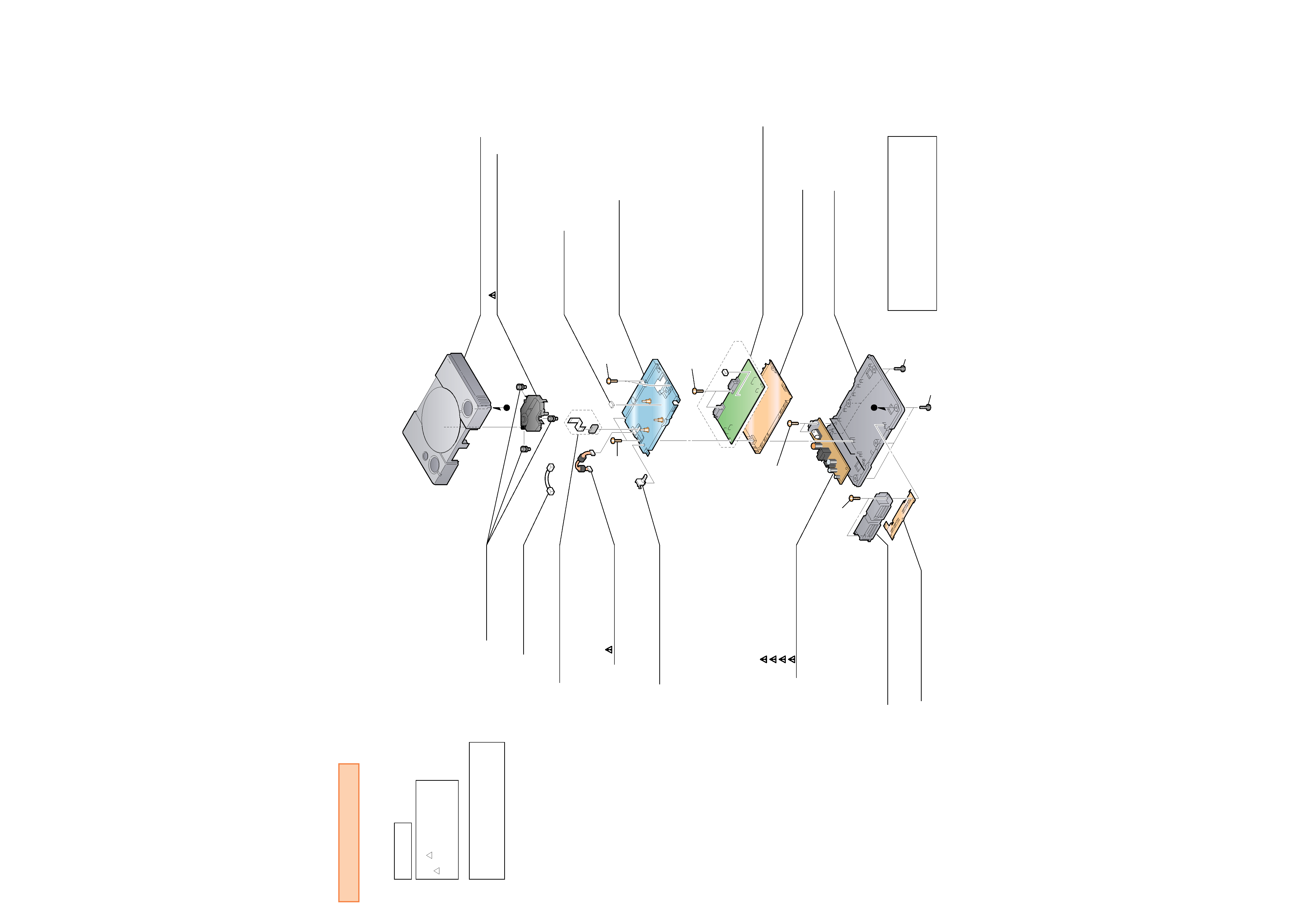
Screw
+BV 3X14
Screw
+BV 3X14
Screw
+BV 3X12
A
Screw
+BV 3X12
Screw
+BV 3X12
Screw
+BV 3X12
Screw
+BV 3X12
AEM
8-820-067-01 DEVICE OPTICAL KSM-440AEM
A
LOWER 3-056-223-01 CABINET (LOWER)
L-SHIELD 3-056-229-01 SHIELD (LOWER)
UPPER X-3949-786-1 CABINET(UPPER) ASSY (9000) (9003)
UPPER X-3949-787-1 CABINET(UPPER) ASSY (9001)
UPPER X-3949-788-1 CABINET(UPPER) ASSY (9002)
PU-23 A-6791-936-A MOUNTED CIRCUIT BOARD, PU-23 (9000)
PU-23 A-6791-939-A MOUNTED CIRCUIT BOARD, PU-23 (9001)
PU-23 A-6791-937-A MOUNTED CIRCUIT BOARD, PU-23 (9002)
PU-23 A-6791-938-A MOUNTED CIRCUIT BOARD, PU-23 (9003)
SUB X-3949-789-1 FRAME ASSY, SUB
P 3-972-494-01 CUSHION P
PSB
1-468-366-11 POWER BLOCK (9000)
PSB
1-468-365-11 POWER BLOCK (9001)
PSB
1-468-303-13 POWER BLOCK (9002)
PSB
1-468-243-11 POWER BLOCK (9003)
PM 1-945-377-31 HARNESS (PM-86)
INSU 3-965-376-01 INSULATOR
FFC A-6775-347-A CABLE BLOCK ASSY, FLAT
TERMINAL 1-694-473-12 TERMINAL BOARD (FRONT)
S-FRONT 3-052-152-02 SHIELD (FRONT)
PP
1-959-132-13 HARNESS (PP-169)
STOPPER 3-052-440-02 STOPPER, HARNESS
CAUTION :
for SCPH9001
CAUTION SERIAL No. LABEL (3- 969- 533- 11)
must be putted on the top of TERMINAL BOARD
according to the standard of UL1492.
SECTION 2
EXPLODED VIEW
The components identified by
mark ! or dotted line with mark.
!
are critical for safety.
Replace only with part number
specified.
CAUTION
CAUTION :
Use of controls or adjustments or performance
of procedures other than those specified herein
may result in hazardous radiation exposure.
-- 4 --
SCPH-9000 SERIES
Reproduction Prohibited
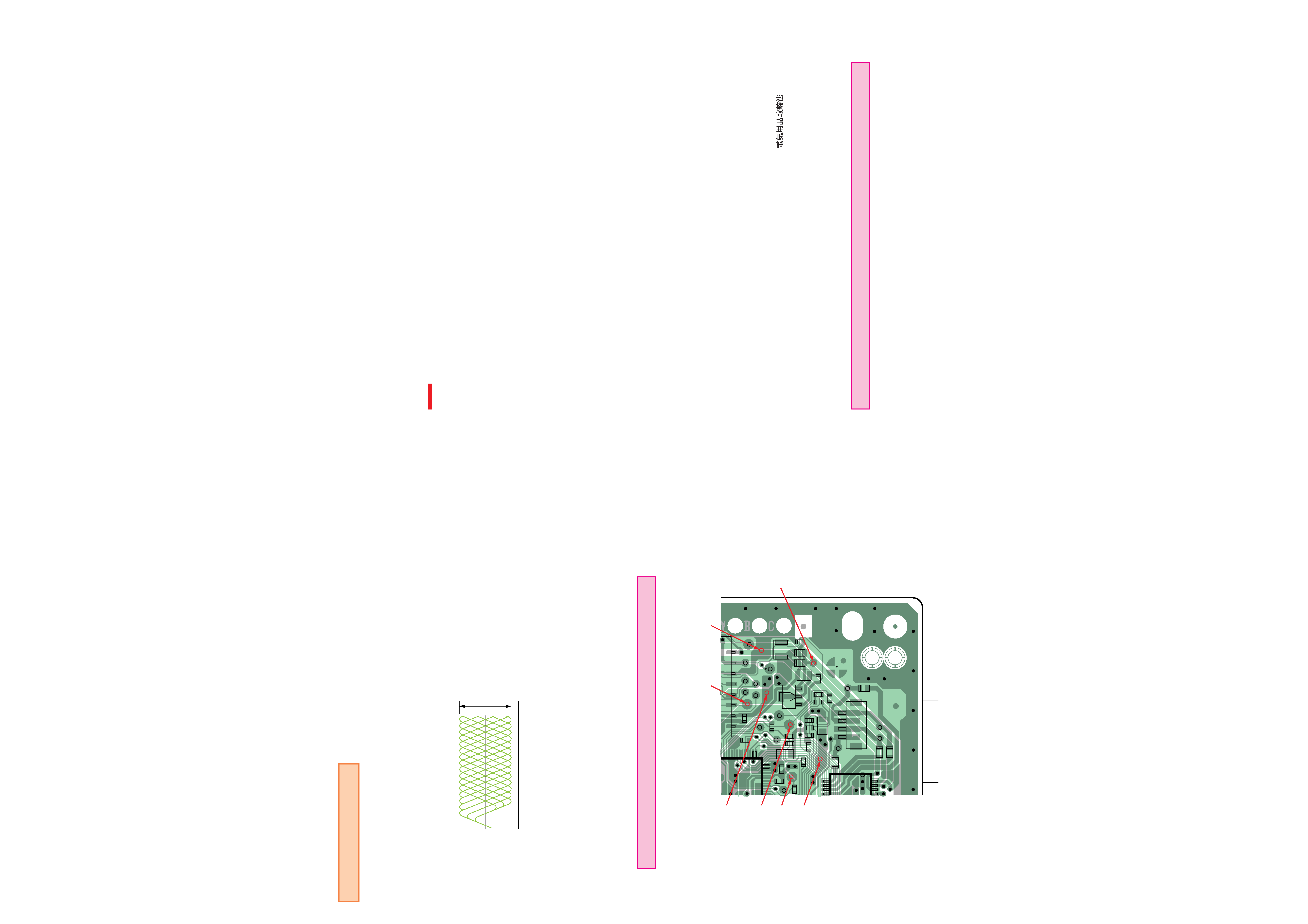
3-1. Test Specification
RF Level
0.90 to 1.35 Vp-p (Test point : Between CL704 and CL710)
Use SCD-2700 DISC when measured RF level.
Use an oscilloscope with input impedance over 10 M
RF Jitter
Less 9.0 nS (Measuring with KSM- 6135S JITTER METER.)
Less 27.0 nS (Measuring with KSM- 6235S JITTER METER.)
PP Level
1.1 ±0.6 Vp-p (Test point : Between CL776 and CL710)
Use LPF (fc = 10 kHz)
Tracking Level 1.3 ±0.6 Vp-p (Test point : Between CL709 and CL710 )
Caution
Vc Line (CL710) do not wire to other lines together.
Caution.
Vc Line (CL710) do not make common use with GND line.
Test Point for PU-23 Board.
1-674-987-
52
1
1
4
15
14
59
13 15
53
R747
R775
R770
R793
R750
R732
R733
FB703
C742
C720
C726
C721
L701
C701
R723
CL760
CL708
CL706
CL780
CL778
CL777
CL776
CL790
C741
CL791
CL711
CL709
CL728
CL786
CL784
CL787
CL785
CN701
FB701
FB704
CL775
CL710
Q701
CL316
CL704
CL727
C729
C725
C718
C761
C716
C738
C739
HA002
R727
FB702
R717
CL779
11
12
1-674-987-
CL776
CL727
CL709
CL710
CL704
CL706
CL728
SECTION 3
ADJUSTMENT
· RF signal waveform (Eye pattern)
0 V
VOLT/DIV
TIME/DIV
0.90 to 1.35 Vp-p
: 0.2 V
: 500 nS
SECTION 4
NOTICE
Circuit Notes :
: B+ Line.
Voltages are measured with a Digital Multimeter. (Input impedance over 10 M
.)
Waveforms easured with an Oscilloscope DC coupled.
Semiconductors.
In each case. u : µ, for example ; uA : µA, uPA : µPA, uPB : µPA, uPC : µPA.
Unit Descriptions :
Capacitors.
Unit of Capacitor is µF and pF, for example ; uF : µF, pF : µµF.
Resisters.
Unit of Resistor is
.
Inductance.
Unit of Inductance is µH and mH
Parts List Notes:
Due to standardization, Parts may be different from the parts described in the diagrams or used on
the Set.
Attention :
Dielectric voltage withstand test and Insuiation resistance test.
After repair complete. Dielectric voltage withstand test and Insulation resistance test to be con-
ducted according to the regulation of IEC-65 EN60065 or UL1492 or
.
About replacement of Optical Device.
Before exchanging the Optical Device, Check the RF level, Jitter, Eye pattern, Focus gain and
Tracking error. When Optical Device is meet the specification, Playback the PS1 testing disc
"QA-DISC" or "AGING DISC" for checking the double speed and sled mechanism ability.
Optical Device should have to no exchange when spacification and ability are satisfied.