HOME THEATER SPEAKER SYSTEM
SA-VF700ED
US Model
Canadian Model
AEP Model
UK Model
SPECIFICATIONS
SA-VF700ED is front speaker system in SA-VS700ED.
9-961-024-01
2003G02-1
© 2003.07
Ver 1.0 2003.07
Sony Corporation
Home Audio Company
Published by Sony Engineering Corporation
SERVICE MANUAL
For the U.S. model
AUDIO POWER SPECIFICATIONS
POWER OUTPUT AND TOTAL HARMONIC
DISTORTION:
With 3 ohms loads both subwoofer driven, from 20 - 200 Hz; rated 250
watts minimum RMS power, with no more than 0.8% total harmonic
distortion from 250 milliwatts to rated output.
SA-VF700ED
Speaker system
2 way and built-in subwoofer
Speaker units Subwoofer:
11 cm (4 3/8 in.), cone type
Woofer: 8 cm (3 1/4 in.), cone type
Tweeter: 2.5 cm (1 in.), dome type
Enclosure type
Bass reflex
Rated impedance
8 ohms
Power handling capacity
Maximum input power:
170 watts
Sensitivity level
88 dB (1 W, 1 m)
Frequency range
20 Hz - 70,000 Hz
Inputs
LINE IN: input pin jack
SPEAKER IN: speaker cord
General
Power requirements
US, CND model:120 V AC, 60 Hz
AEP, UK model :220 -230 V AC, 50/60 Hz
Power consumptions
250 W
1 W (standby mode)
Dimensions (w/h/d)
Approx. 300 x 1,200 x 300 mm
(11 7/8 x 47 1/4 x 11 7/8 in.)
Mass
AMP SIDE: Approx. 16.7 kg
(36 lb 13.07 oz)
NON AMP SIDE: Approx. 15.0 kg
(33 lb 1.11 oz)
Supplied accessories
Audio connecting cord, 5 m (16 ft 1/2 in.) (1)
Subwoofer connecting cord, 5m (16 ft 1/2 in.) (1)
Speaker connecting cords, 5 m (16 ft 1/2 in.) (2)
Design and specifications are subject to change without notice.
2
SA-VF700ED
Specifications ........................................................................... 1
1. GENERAL ...................................................................... 3
2. SERVICING NOTES
2-1. Service Position For Power Board ............................. 3
2-2. Service Position For Control Board ........................... 4
2-3. Wire Stopper ............................................................... 4
3. DISASSEMBLY
3-1. Ring ASSY, Grill Frame (Front) ASSY ...................... 5
3-2. Bottom Section ........................................................... 6
3-3. Subwoofer (SP103) .................................................... 7
4. DIAGRAMS
4-1. Circuit Boards Location ............................................. 9
4-2. Schematic Diagram Control Section .................. 10
4-3. Printed Wiring Boards Control Section ............... 11
4-4. Schematic Diagram Power Section .................... 12
4-5. Printed Wiring Boards
Power Section (Side A) ...................................... 13
Printed Wiring Boards
Power Section (Side B) ...................................... 14
5. EXPLODED VIEWS
5-1. Base Section (L-CH) ................................................ 15
5-2. Speaker Section (L-CH) ........................................... 16
5-3. Bottom Section (L-CH) ............................................ 17
5-4. Bottom Section (R-CH) ............................................ 18
5-5. Speaker Section (R-CH) ........................................... 19
6. ELECTRICAL PARTS LIST ................................... 20
TABLE OF CONTENTS
SAFETY CHECK-OUT
After correcting the original service problem, perform the
following safety checks before releasing the set to the customer:
Check the antenna terminals, metal trim, "metallized" knobs,
screws, and all other exposed metal parts for AC leakage. Check
leakage as described below.
LEAKAGE
The AC leakage from any exposed metal part to earth Ground
and from all exposed metal parts to any exposed metal part
having a return to chassis, must not exceed 0.5 mA (500
microampers). Leakage current can be measured by any one of
three methods.
1. A commercial leakage tester, such as the Simpson 229 or
RCA WT-540A. Follow the manufacturers' instructions to
use these instruments.
2. A battery-operated AC milliammeter. The Data Precision
245 digital multimeter is suitable for this job.
3. Measuring the voltage drop across a resistor by means of a
VOM or battery-operated AC voltmeter. The "limit"
indication is 0.75 V, so analog meters must have an accurate
low-voltage scale. The Simpson 250 and Sanwa SH-63Trd
are examples of a passive VOM that is suitable. Nearly all
battery operated digital multimeters that have a 2V AC range
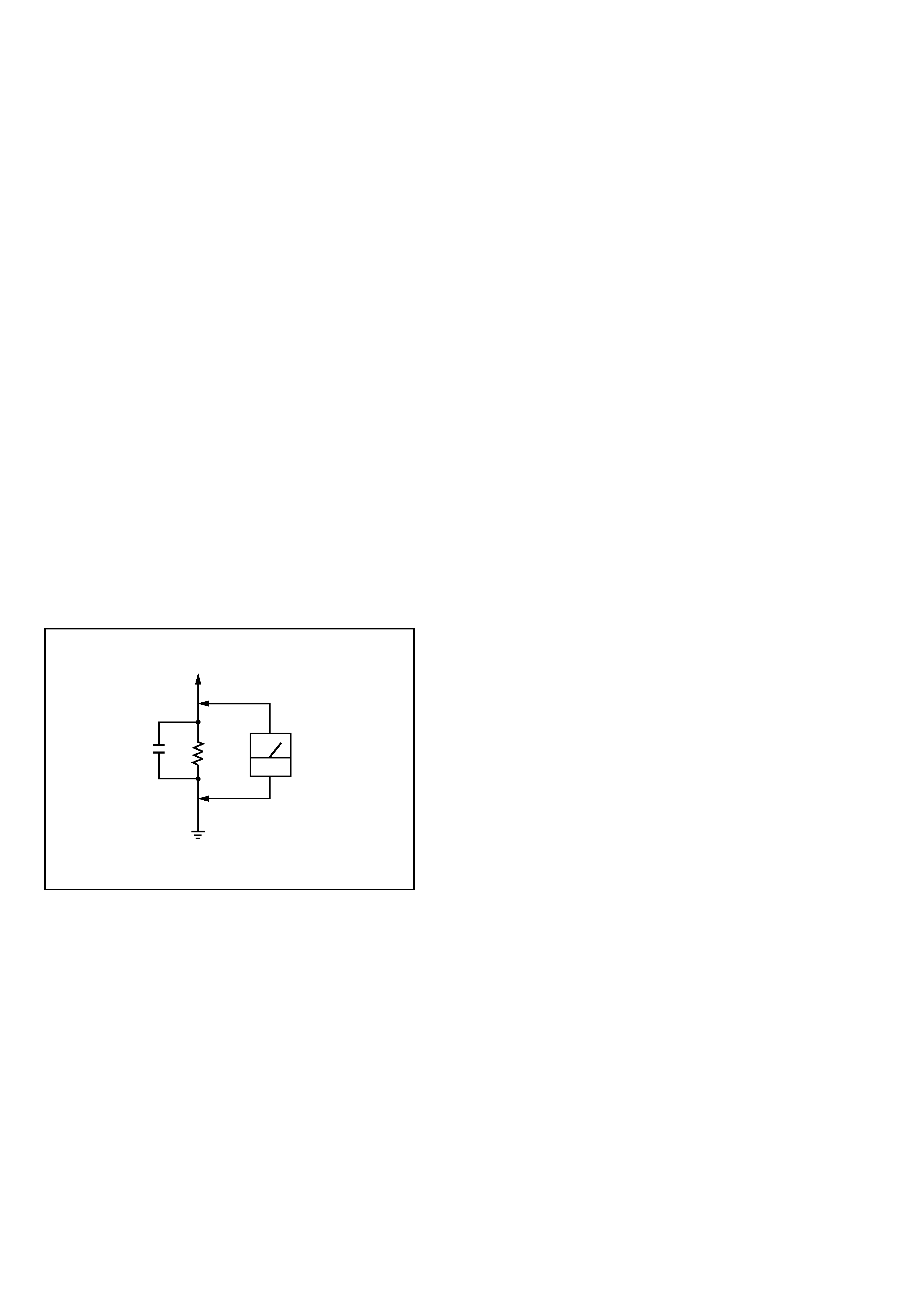
are suitable. (See Fig. A)
Fig. A. Using an AC voltmeter to check AC leakage.
0.15µF
To Exposed Metal
Parts on Set
1.5k
AC
voltmeter
(0.75V)
Earth Ground
SAFETY-RELATED COMPONENT WARNING!!
COMPONENTS IDENTIFIED BY MARK 0 OR DOTTED
LINE WITH MARK 0 ON THE SCHEMATIC DIAGRAMS
AND IN THE PARTS LIST ARE CRITICAL TO SAFE
OPERATION. REPLACE THESE COMPONENTS WITH
SONY PARTS WHOSE PART NUMBERS APPEAR AS
SHOWN IN THIS MANUAL OR IN SUPPLEMENTS PUB-
LISHED BY SONY.
ATTENTION AU COMPOSANT AYANT RAPPORT
À LA SÉCURITÉ!!
LES COMPOSANTS IDENTIFIÉS PAR UNE MARQUE 0 SUR
LES DIAGRAMMES SCHÉMATIQUES ET LA LISTE DES
PIÈCES SONT CRITIQUES POUR LA SÉCURITÉ DE
FONCTIONNEMENT. NE REMPLACER CES COMPOSANTS
QUE PAR DES PIÈCES SONY DONT LES NUMÉROS SONT
DONNÉS DANS CE MANUEL OU DANS LES SUPPLÉMENTS
PUBLIÉS PAR SONY.
SA-VF700ED
3
SECTION 1
GENERAL
This section is extracted from
instruction manual.
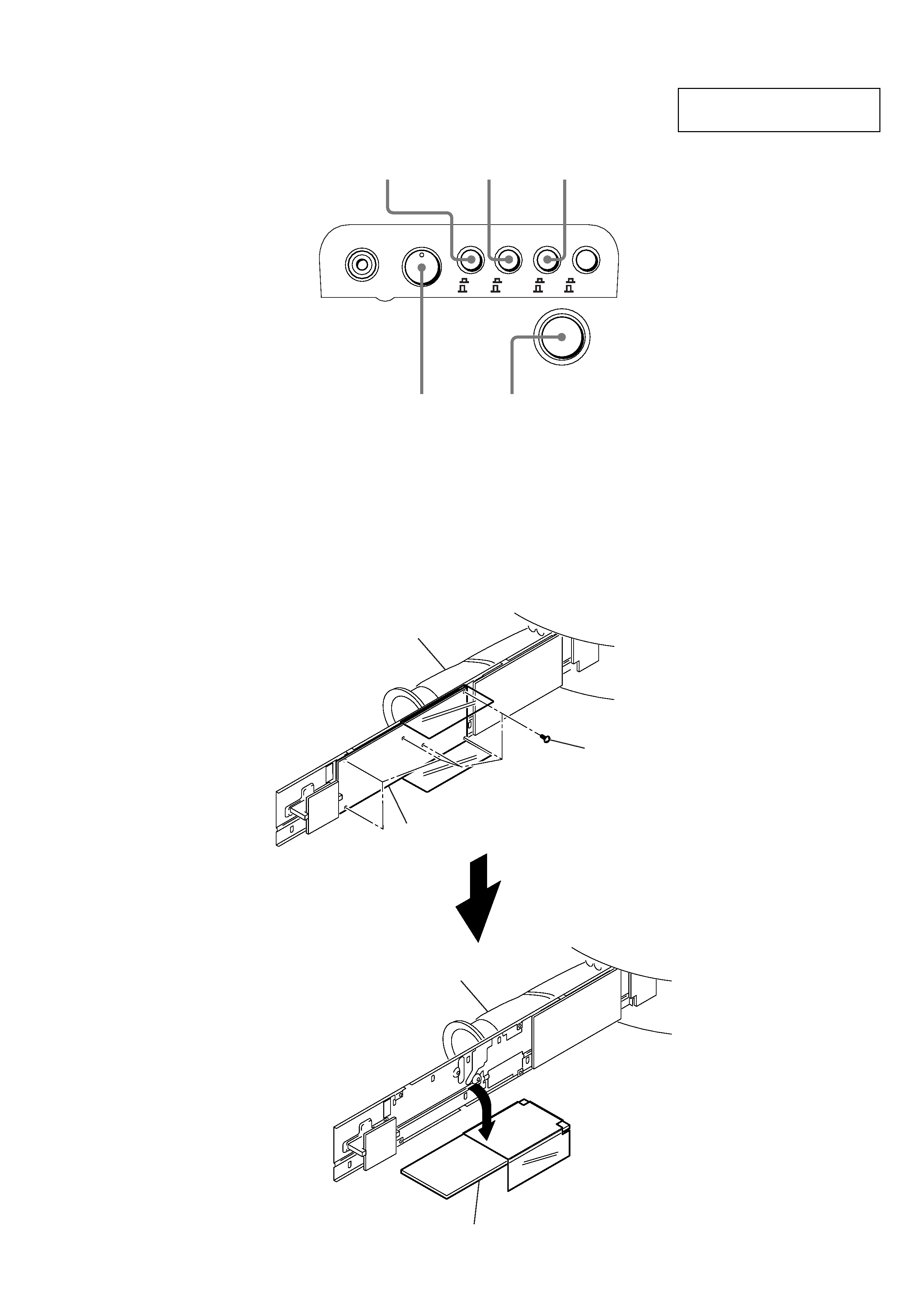
· Location of controls
POWER
SW LEVEL
BOOST
PHASE
POWER SAVE
SUB WOOFER IN
BOOST
SW LEVEL
MIN
MAX
ON
OFF
AUTO
OFF
PHASE
POWER SAVE INPUT SELECTOR
NORM
POWER
REVERSE
SW IN
SPEAKER IN
SECTION 2
SERVICING NOTES
2-1. SERVICE POSITION FOR POWER BOARD
Six screws (+BVTP 3 x 6)
Power board
Bottom (L) ASSY
Power board
Bottom (L) ASSY
4
SA-VF700ED
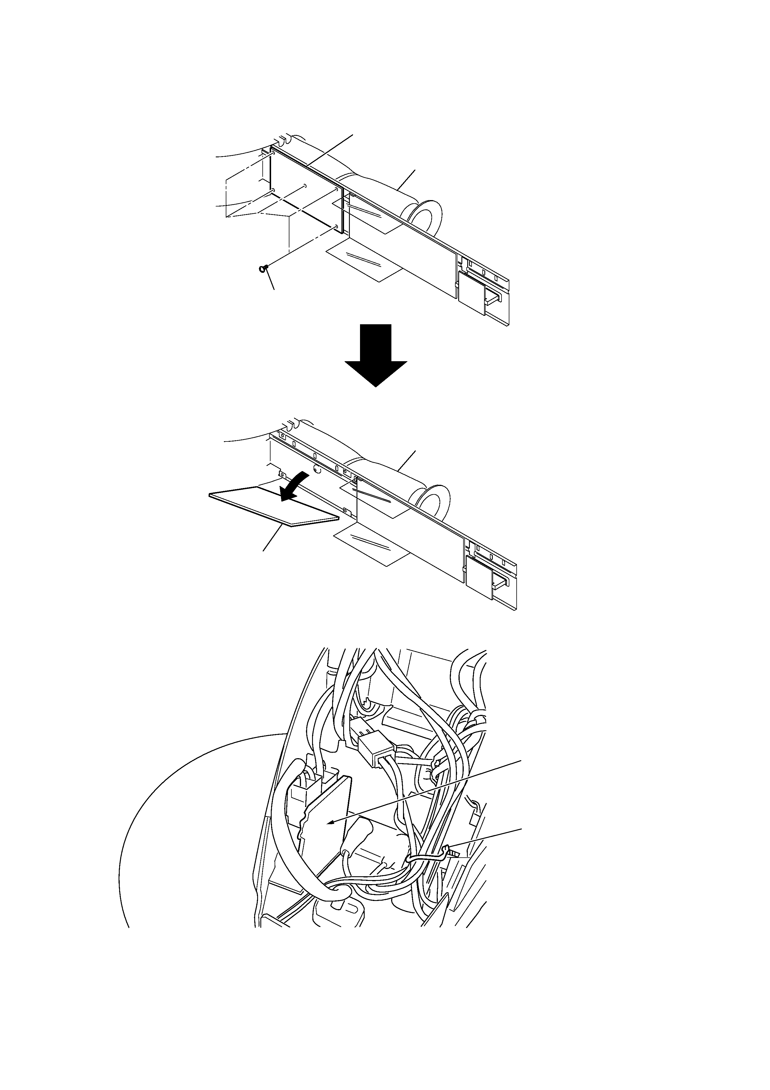
2-2. SERVICE POSITION FOR CONTROL BOARD
Five screws
Control board
Bottom (L) ASSY
Control board
Bottom (L) ASSY
Secure the wires not to touch the primary side of the power supply.
%
Primary side of the
power supply
Wire stopper
2-3. WIRE STOPPER
SA-VF700ED
5
SECTION 3
DISASSEMBLY
Be careful not to break the tweeter cone, because it is so thin.
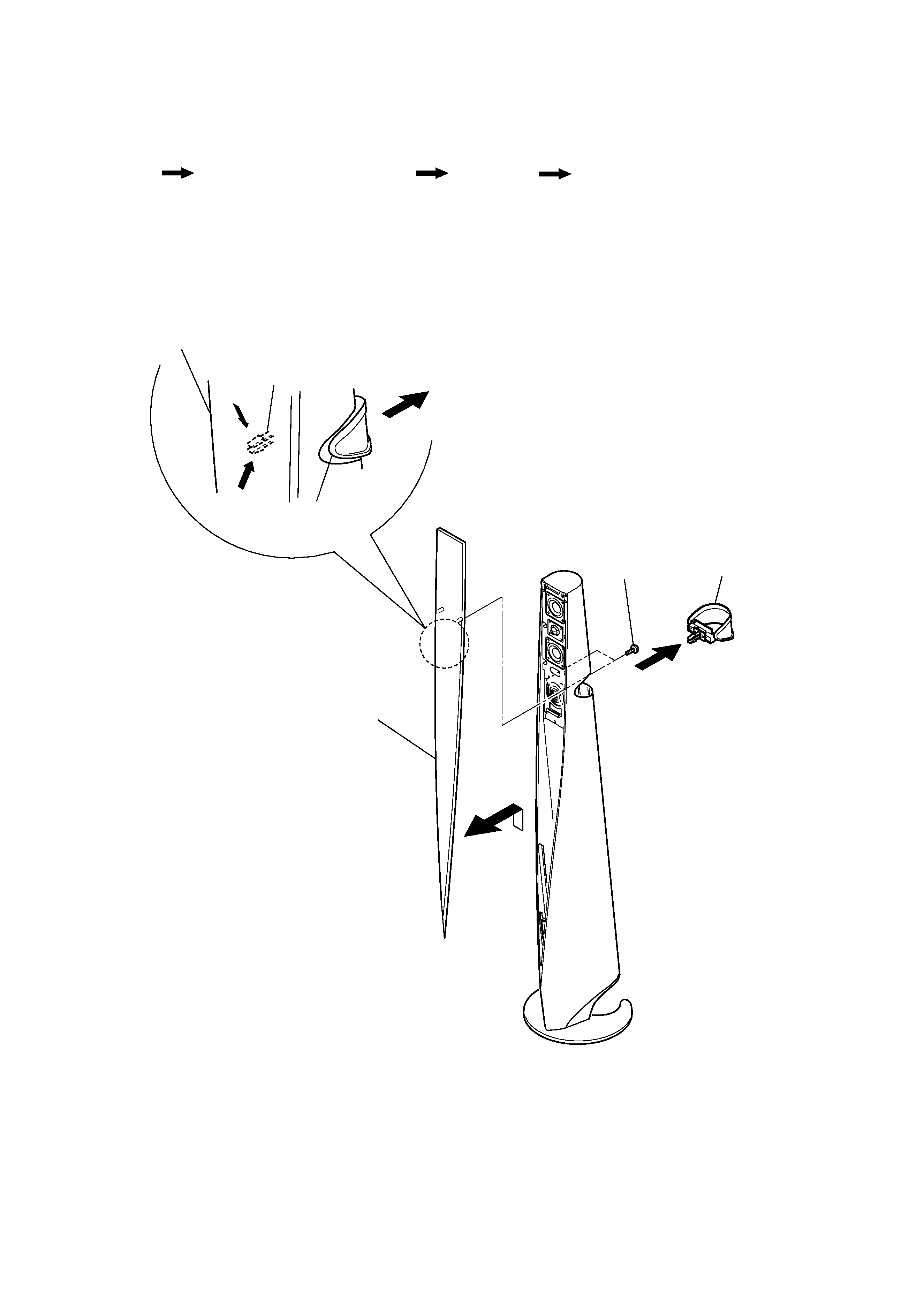
Ring ASSY, Grill frame (front) ASSY
Set
Subwoofer (SP103)
Bottom section
3-1. RING ASSY, GRILL FRAME (FRONT) ASSY
2
5
3
Ring ASSY
Ring ASSY
Claws
6
Grill frame (front) ASSY
Grill frame (front) ASSY
1
a
a
b
4
Tow screws
(+BVTP 4X14)
Pick the claws of Ring ASSY in the arrow a direction over the
net of Grill frame (front) ASSY and push Ring ASSY out in the
arrow b direction.
Note : Follow the disassembly procedure in the numerical order given.