SERVICE MANUAL
SS-V225 (Front and rear speakers)
Speaker system
Full range, magnetically
shielded
Speaker units
5
× 9 cm, cone type
Enclosure type
Bass reflex
Rated impedance
8 ohms
Power handling capacity
Maximum input power:
100 watts
Sensitivity level
86 dB (1 W, 1 m)
Frequency range
90 Hz - 20,000 Hz
Dimensions (w/h/d)
Approx. 70
× 151 ×
126 mm, including front
grille
Mass
Approx. 550 g each
SS-CN225 (Center speaker)
Speaker system
Full range
× 2,
magnetically shielded
Speaker units
5
× 9 cm, cone type
Enclosure type
Bass reflex
Rated impedance
8 ohms
Power handling capacity
Maximum input power:
120 watts
Sensitivity level
88 dB (1 W, 1 m)
Frequency range
90 Hz - 20,000 Hz
Dimensions (w/h/d)
Approx. 301
× 70 ×
126 mm, including front
grille
Mass
Approx. 1.1 kg
SA-WMS225 (subwoofer)
Speaker system
Active subwoofer,
magnetically shielded
Speaker unit
Woofer: 16 cm, cone type
Enclosure type
Advanced SAW type
Amplifire section
Continuous RMS power output
50 W(8 ohms, 20 - 150 Hz,
0.8% THD)
Reproduction frequency range
28 Hz - 200 Hz
High frequency cut-off frequency
200 Hz
Inputs
LINE IN (input pin jack)
SPEAKER IN (input terminals)
Outputs
LINE OUT (output pin jack)
SPEAKER OUT (output terminals)
General
Power requirements
220 - 230 V AC, 50/60 Hz
Power consumptions
50 W
Dimensions (w/h/d)
Approx. 205
× 385 × 385
mm, including front grille
Mass
Approx. 10.5 kg
Supplied accessories
Foot pads (20)
Monaural connecting cord (1 phono to 1 phono) (1)
Speaker connecting cords, 10 m (2)
Speaker connecting cords, 3.5 m (3)
Speaker connecting cords, 2.5 m (2)
Design and specifications are subject to change without
notice.
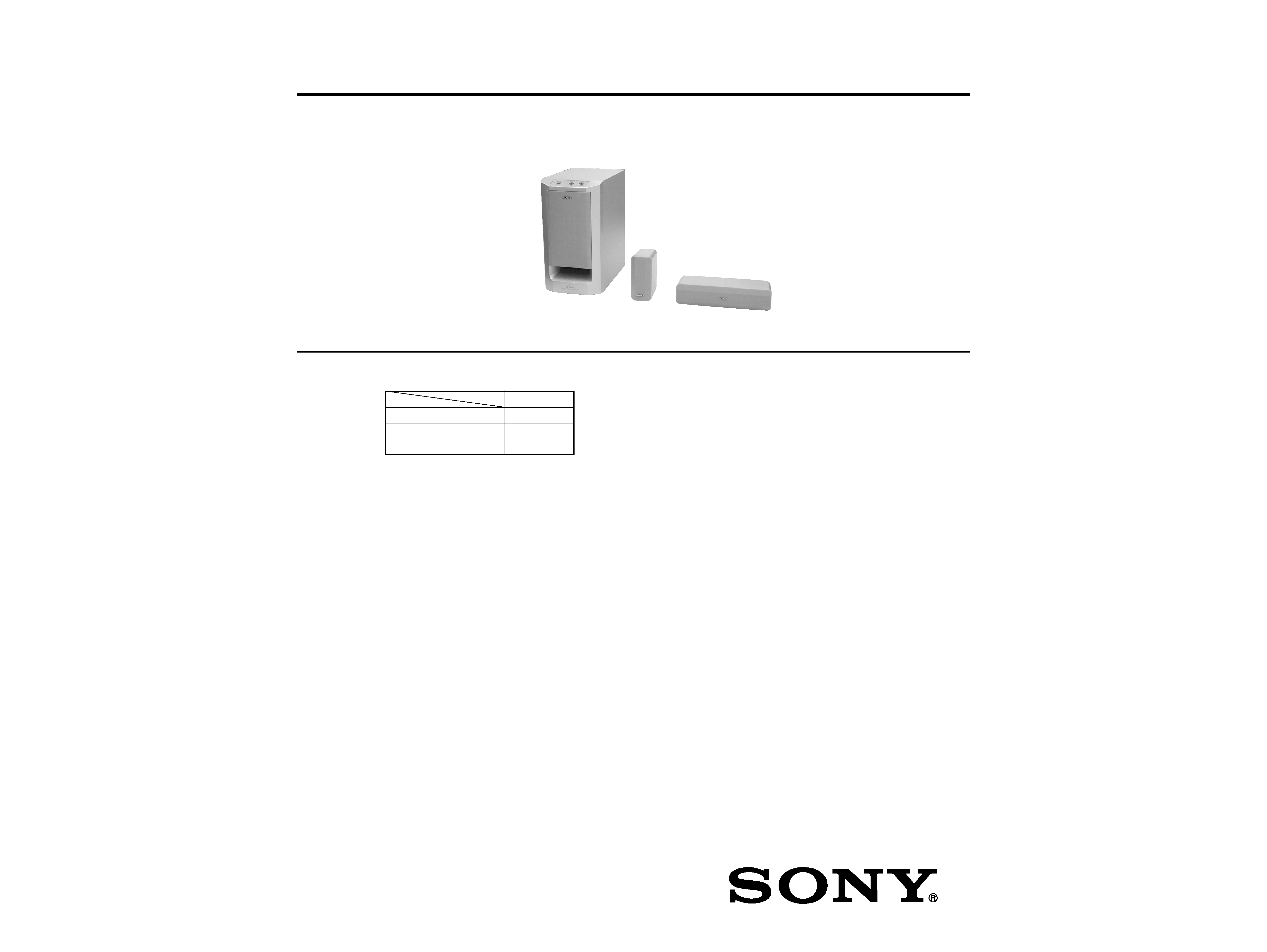
MICRO SATELLITE SYSTEM
AEP Model
UK Model
Ver 1.0 2001.02
9-929-575-11
Sony Corporation
2001B0500-1
Audio Entertainment Group
C
2001.2
General Engineering Dept.
SPECIFICATIONS
SA-VE225/WMS225/
SS-CN225/V225
· SA-VE225 consists of the following models respectively.
SA-VE225
Active Subwoofer
SA-WMS225
Center Speaker
SS-CN225
Front and Rear Speakers
SS-V225
SAFETY-RELATED COMPONENT WARNING!!
COMPONENTS IDENTIFIED BY MARK 0 OR DOTTED
LINE WITH MARK 0 ON THE SCHEMATIC DIAGRAMS
AND IN THE PARTS LIST ARE CRITICAL TO SAFE
OPERATION. REPLACE THESE COMPONENTS WITH
SONY PARTS WHOSE PART NUMBERS APPEAR AS
SHOWN IN THIS MANUAL OR IN SUPPLEMENTS PUB-
LISHED BY SONY.
SA-WMS225
SS-V225
SS-CN225
2
SA-VE225/WMS225/SS-CN225/V225
SECTION 1
DIAGRAMS
1-1.
NOTE FOR PRINTED WIRING BOARDS AND SCHEMATIC DIAGRAMS
Note on Printed Wiring Boards:
· X : parts extracted from the component side.
·
: Pattern from the side which enables seeing.
Note on Schematic Diagram:
· All capacitors are in
µF unless otherwise noted. pF: µµF
50 WV or less are not indicated except for electrolytics
and tantalums.
· All resistors are in
and 1/4 W or less unless otherwise
specified.
· 2 : nonflammable resistor.
· 5 : fusible resistor.
· C : panel designation.
· A : B+ Line.
· B : B Line.
· Voltages are dc with respect to ground under no-signal
conditions.
· Voltages are taken with a VOM (Input impedance 10 M
).
Voltage variations may be noted due to normal produc-
tion tolerances.
· Signal path.
F
: AUDIO
Note: The components identified by mark 0 or dotted line
with mark 0 are critical for safety.
Replace only with part number specified.
SA-VE225/WMS225/SS-CN225/V225
3
3
THERMAL
SHUTDOWN
BIPOLAR
TRANSCONDACTANCE
INPUT STAGE
STANDBY/
MUTE
BOOST-
STRAP
MOS GAIN &
LEVEL SHIFTING
STAGE
STBY
-GND
IN
IN+
IN+
MUTE
NC
BOOSTSTRAP
+VS
VS
STBY
MUTE
NC
NC
+PWVS
OUT
PWVS
14 15
12
13
10
11
8 9
6
7
5
3
4
1 2
+
MOS
OUTPUT
STAGE
SHORT
CIRCUIT
PROTECTION
1
2
3
4
5
6
7
8
OVER LOAD DET
F/F
OFFSET DET
LATCH/
AUTORESET
VCC ON
MUTE
AC OFF
DET
OVER
LOAD
DET
OFFSET
DET
AUTO
RESET
AC
OFF
DET
GND
RELAY
DRIVE
VCC
ON
MUTE
VCC
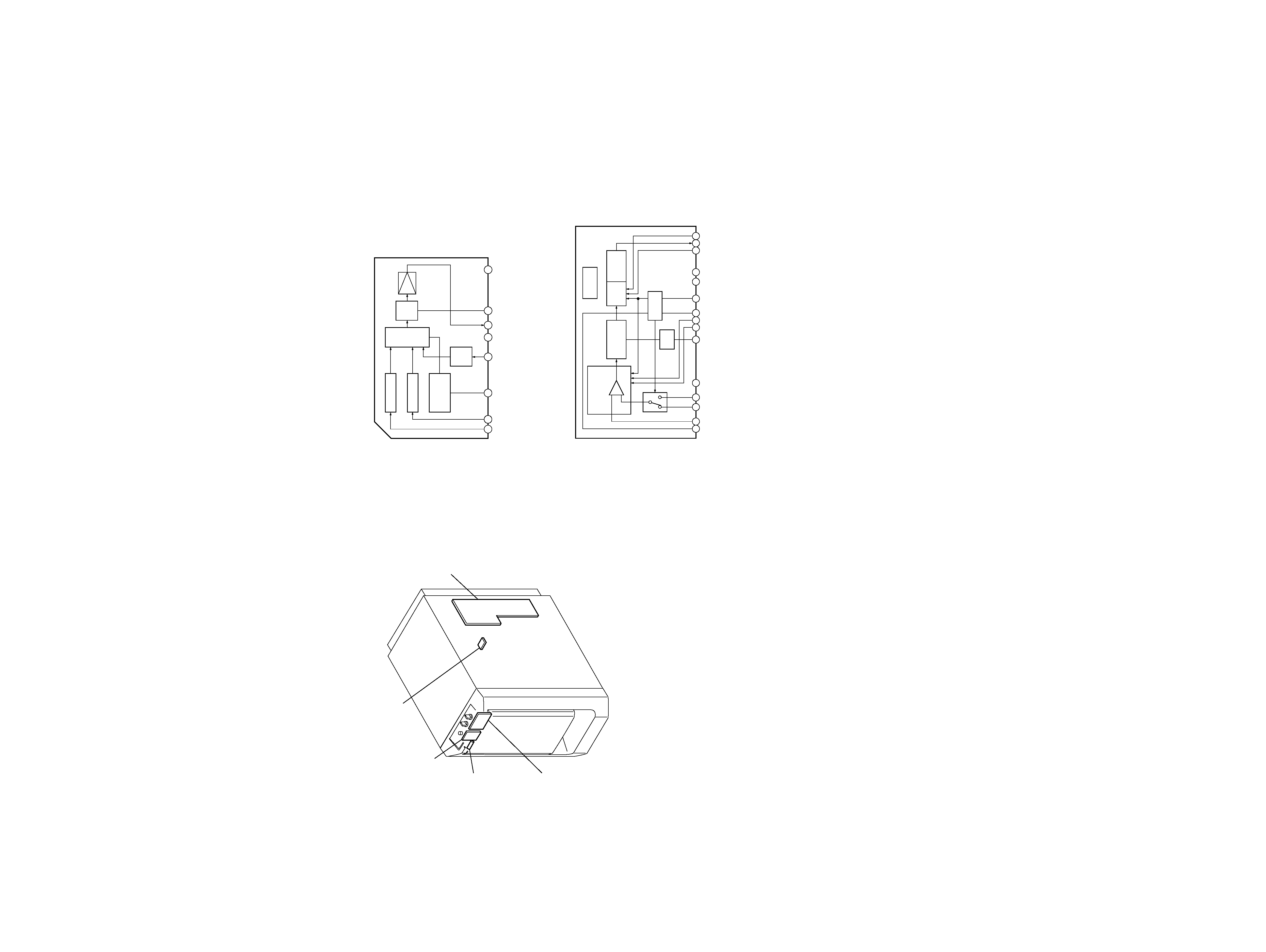
· IC Block Diagrams
MAIN Board
IC302
µPC1237HA
· Circuit Boards Location
SA-WMS225
POWER IC board
POWER SW board
LED board
CONTROL board
MAIN board
POWER IC Board
IC401
TDA7294
SA-VE225/WMS225/SS-CN225/V225
4
4
LED BOARD
LEVEL
MODE
MUSIC
MOVIE
(POWER)
SP1
(SPEAKER)
11
1-676-716-
(13)
11
(13)
11
(13)
11
(11)
MAIN BOARD
POWER
T501
POWER
TRANSFORMER
AC
IN
11
(13)
CONTROL BOARD
POWER SW
BOARD
POWER IC BOARD
SPEAKER
R
L
OUT
IN
r
1-676-713
LINE
1-677-993-
1-676-714-
1-676-565-
R102
R101
R103 R104
12
A
B
C
D
E
F
G
H
3456789
10
11
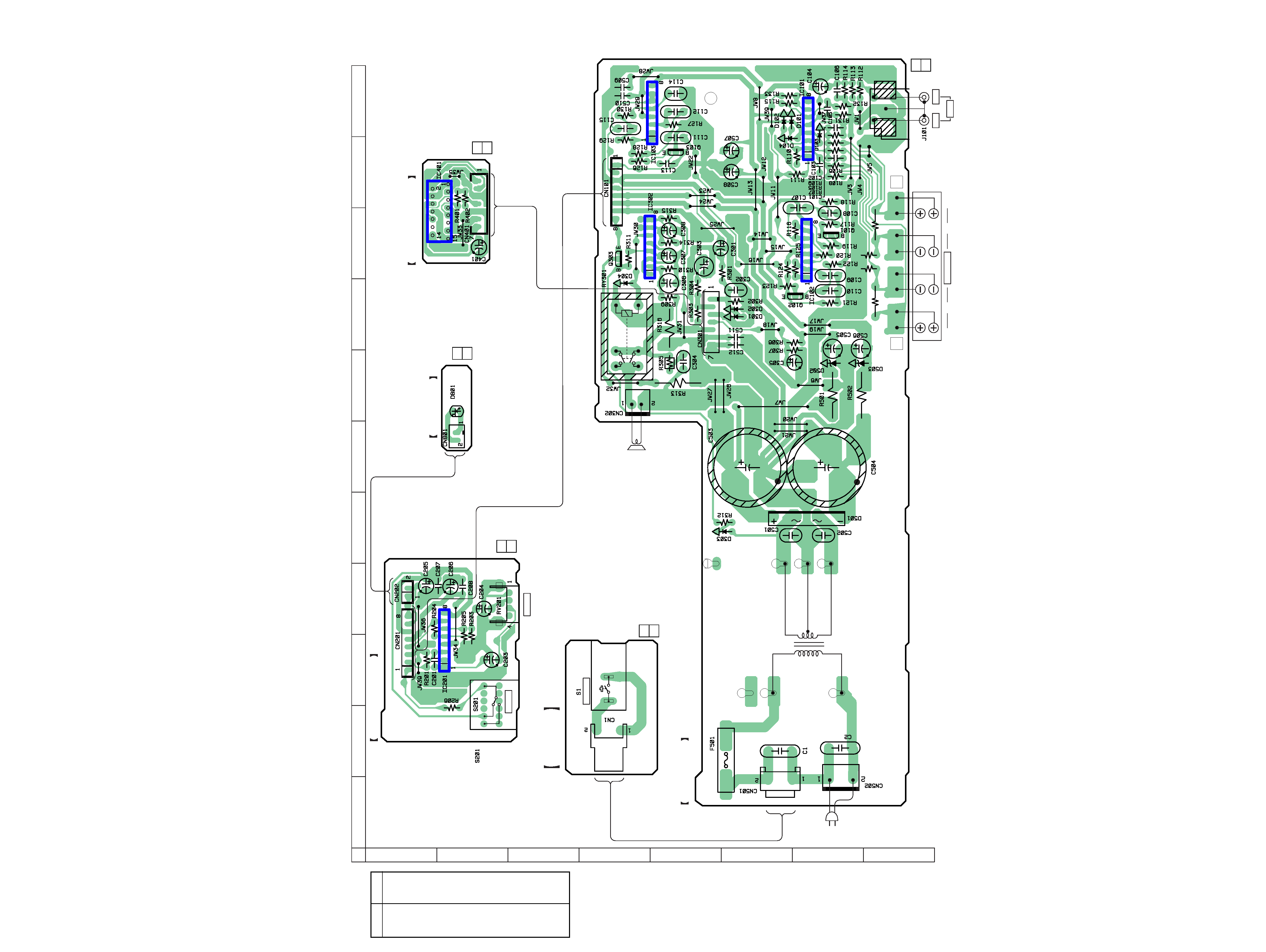
1-2.
PRINTED WIRING BOARDS (SA-WMS225)
· See page 3 for Circuit Boards Location.
· Semiconductor
Location
Ref. No.
Location
D101
G-11
D102
F-11
D103
G-10
D104
G-10
D301
F-8
D302
F-8
D303
F-5
D304
D-8
D501
G-5
D502
G-7
D503
H-7
D801
B-7
IC101
G-11
IC102
G-9
IC103
E-11
IC201
B-3
IC302
E-10
IC401
B-10
Q101
G-9
Q102
G-8
Q103
E-10
Q303
D-9
SA-VE225/WMS225/SS-CN225/V225
5
5
OVER
LOAD
DET
OFFSET
DET
AUTO
RESET
AC
OFF
DET
GND
VCC
ON
MUTE
VCC
RELA
Y
DRIVE
(1/2)
(1/2)
(2/2)
(2/2)
(2/2)
(1/2)
MIX AMP
(1/2)
(1/2)
HIGH-PASS FILTER
(2/2)
LOW-PASS FILTER
(2/2)
1A 250V
BUFFER
(1/2)
3
2
1
(2/2)
(CHASSIS)
D304
1SS133
7P
7P
RBA-402-SL
RBA-402-SL
RBA-406B
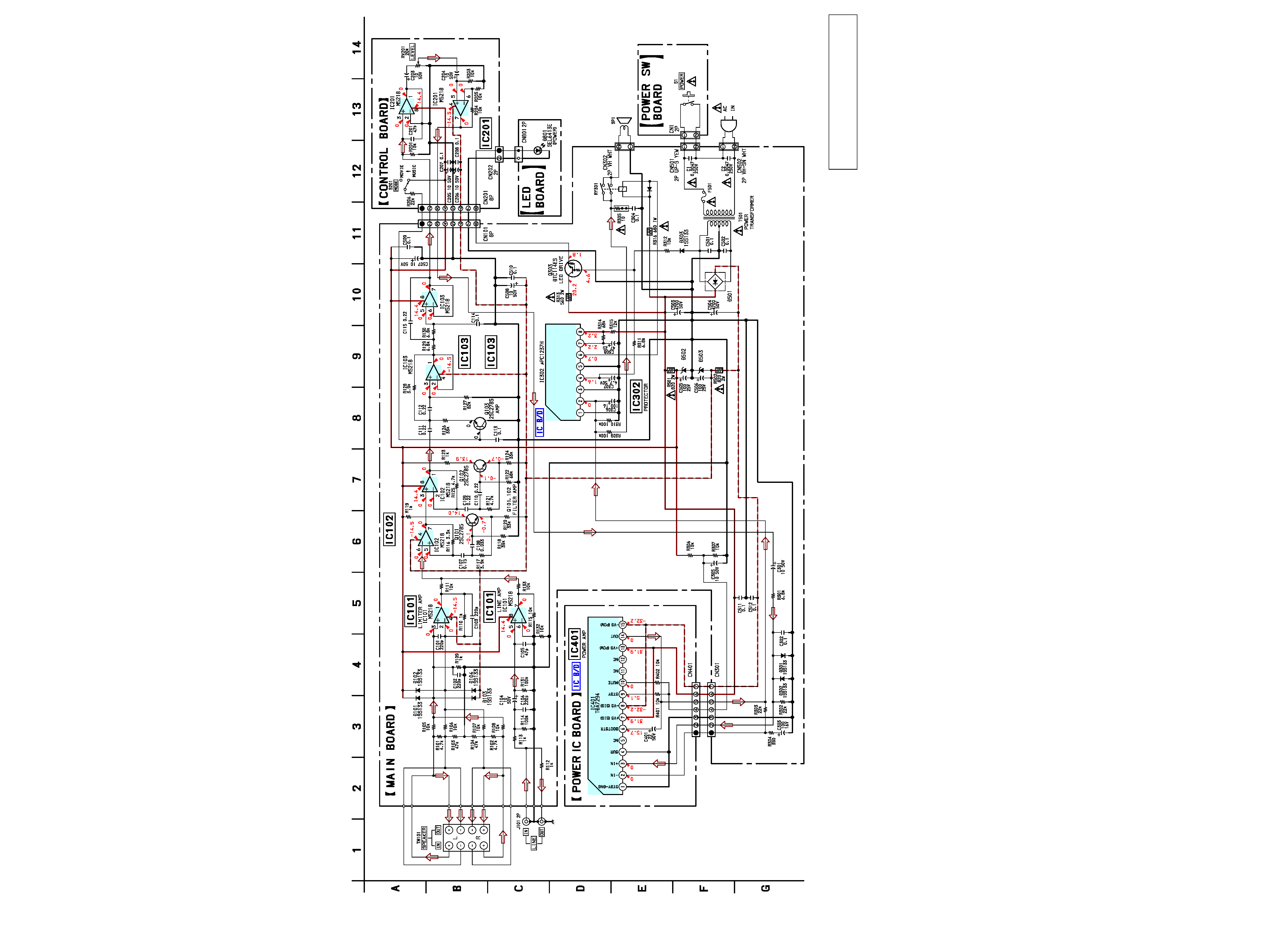
1-3.
SCHEMATIC DIAGRAM (SA-WMS225)
· See page 3 for IC Block Diagrams.
The components identified by mark 0 or dotted
line with mark 0 are critical for safety.
Replace only with part number specified.