SERVICE MANUAL
SAT-T60 RM-Y809
9-965-899-02
SAT-T60
U.S. Model
Canadian Model
HISTORY INFORMATION FOR THE FOLLOWING MANUAL:
ORIGINAL MANUAL ISSUE DATE: 9/2000
ALL REVISIONS AND UPDATES TO THE ORIGINAL MANUAL ARE APPENDED TO THE END OF THE PDF FILE.
REVISION DATE
REVISION TYPE
SUBJECT
9/2000
No revisions or updates are applicable at this time.
9/2002
Reissue complete manual - Updated
SERVICE MANUAL
SAT-T60 RM-Y809
9-965-899-02
SAT-T60
U.S. Model
Canadian Model
SAT-T60
RM-Y809
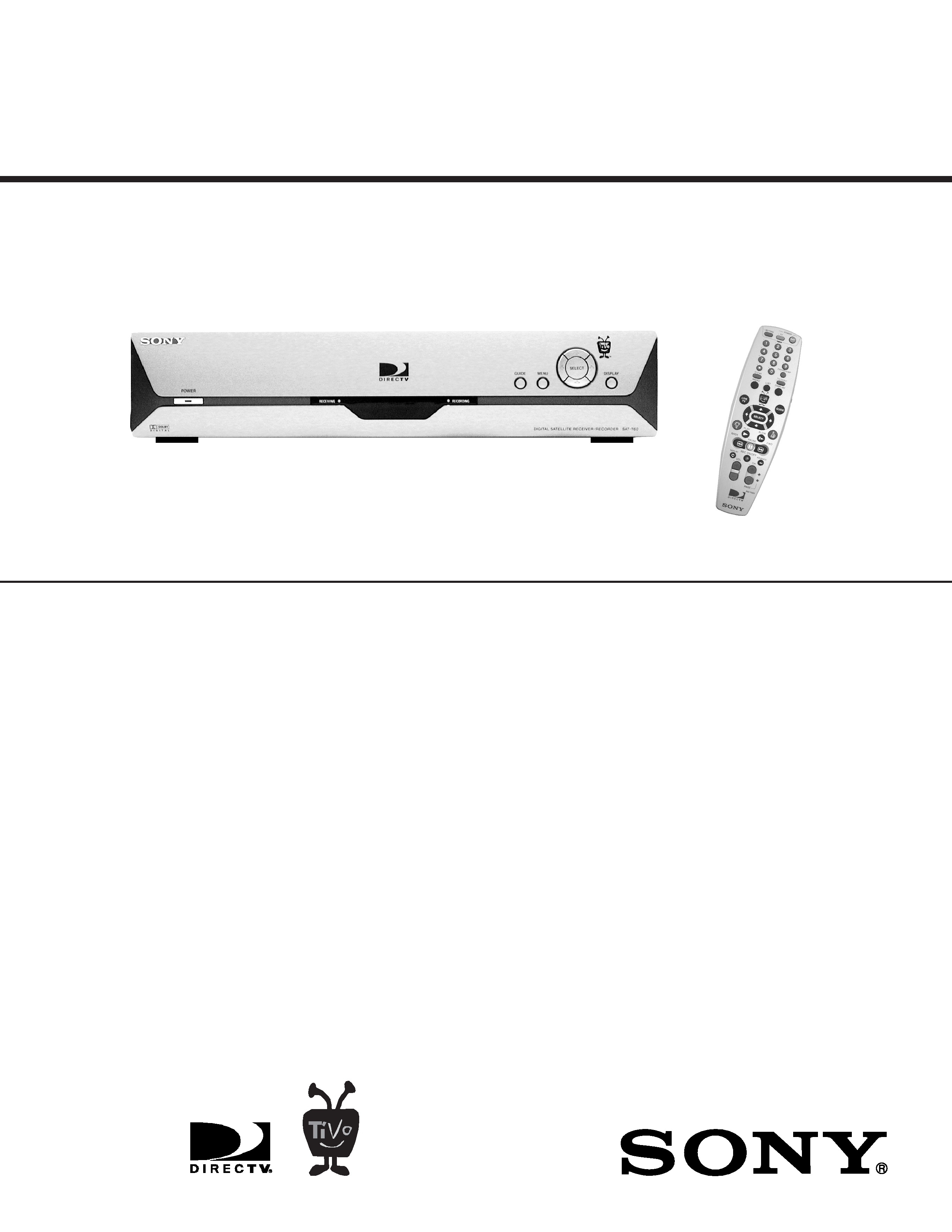
Inputs and Outputs:
Supplied Accessories:
Video Out: S-Video 4-pin mini DIN (1)
Remote Control (1)
Video Out: Composite Video RCA (2)
Size AA (R6) Batteries (1)
Audio Line Out: Stereo L/R RCA (2 pairs)
AC Power Cord (1)
Satellite In: F-Connector Female (2)
RF Coaxial Cable (1)
VHF/UHF In: F-Connector Female (1)
Audio/Video Cable (1)
VHF/UHF (SAT) Out: F-Connector Female (1)
IR Control Cable (1)
Digital Audio Out: Optical (1)
S-Video Cable (1)
Telephone: RJ-11 Female, 2 wire (1)
Phone Cord (1)
Control Out: 3.5 mm Mini Jack Sockets (2)
Phone Splitter (1)
Access Card (1)
General:
Optional Sony-Brand Digital Satellite
Receiver Accessories:
Power Requirements: 120 V AC, 60 Hz
Installation Kit: ANJ-DS2
Local TV Antenna: ANJ-AA1
Amplifier: EAC-DA1
Power Consumption: 60 W
Diplexer: EAC-DD1
Operating Temperature: 21°C to 45°C (70°F to 113°F)
Voltage Switch: EAC-DV2
Operating Humidity: 5% to 80%
Satellite Dish Antenna: SAN-18D
4
Dimensions: Approx. 381 x 76 x 325 mm (w/h/d)
SAN-24MD1
Approx. 15" x 3" x 12 13/16" (w/h/d)
(including projecting parts and controls)
Mass: Approx. 4.6 kg (10 lbs.)
SPECIFICATIONS
TM

-- 3 --
SAT-T60
TABLE OF CONTENTS
Safety Check-Out Instructions .............................................................................................................. 4
1. DISASSEMBLY
1-1. Top Cover Removal ....................................................................................................................... 5
1-2. Front Panel Removal ..................................................................................................................... 5
1-3. Back Panel Information ................................................................................................................. 5
1-4. Hard Drive Assembly Removal...................................................................................................... 6
2. DIAGRAMS
2-1. Block Diagram ............................................................................................................................... 7
2-2. Main Board Schematic Diagram.................................................................................................... 9
3. EXPLODED VIEWS
3-1. Front View ................................................................................................................................... 33
3-2. Rear View .................................................................................................................................... 34
3-3. SAN-18D3 ................................................................................................................................... 35
3-4. SAN-24MD1 ................................................................................................................................ 35
4. ELECTRICAL PARTS LIST .......................................................................................................................... 36
SECTION TITLE
PAGE
-- 4 --
SAT-T60
SAFETY CHECK-OUT
After correcting the original service problem, perform the following
safety checks before releasing the set to the customer:
1. Check the area of your repair for unsoldered or poorly soldered
connections. Check the entire board surface for solder splashes and
bridges.
2. Check the interboard wiring to ensure that no wires are "pinched" or
touching high-wattage resistors.
3. Check that all control knobs, shields, covers, ground straps, and
mounting hardware have been replaced. Be absolutely certain that
you have replaced all the insulators.
4. Look for unauthorized replacement parts, particularly transistors,
that were installed during a previous repair. Point them out to the
customer and recommend their replacement.
5. Look for parts which, though functioning, show obvious signs of
deterioration. Point them out to the customer and recommend their
replacement.
6. Check the line cords for cracks and abrasion. Recommend the
replacement of any such line cord to the customer.
7. Check the B+ and HV to see if they are specified values. Make sure
your instruments are accurate; be suspicious of your HV meter if sets
always have low HV.
8. Check the antenna terminals, metal trim, "metallized" knobs, screws,
and all other exposed metal parts for AC leakage. Check leakage
as described below.
Leakage Test
The AC leakage from any exposed metal part to earth ground and from
all exposed metal parts to any exposed metal part having a return to
chassis, must not exceed 0.5 mA (500 microamperes). Leakage current
can be measured by any one of three methods.
1. A commercial leakage tester, such as the Simpson 229 or
RCA WT-540A. Follow the manufacturers' instructions to use these
instructions.
2. A battery-operated AC milliampmeter. The Data Precision 245 digital
multimeter is suitable for this job.
3. Measuring the voltage drop across a resistor by means of a VOM
or battery-operated AC voltmeter. The "limit" indication is 0.75 V,
so analog meters must have an accurate low voltage scale. The
Simpson's 250 and Sanwa SH-63TRD are examples of passive
VOMs that are suitable. Nearly all battery-operated digital multimeters
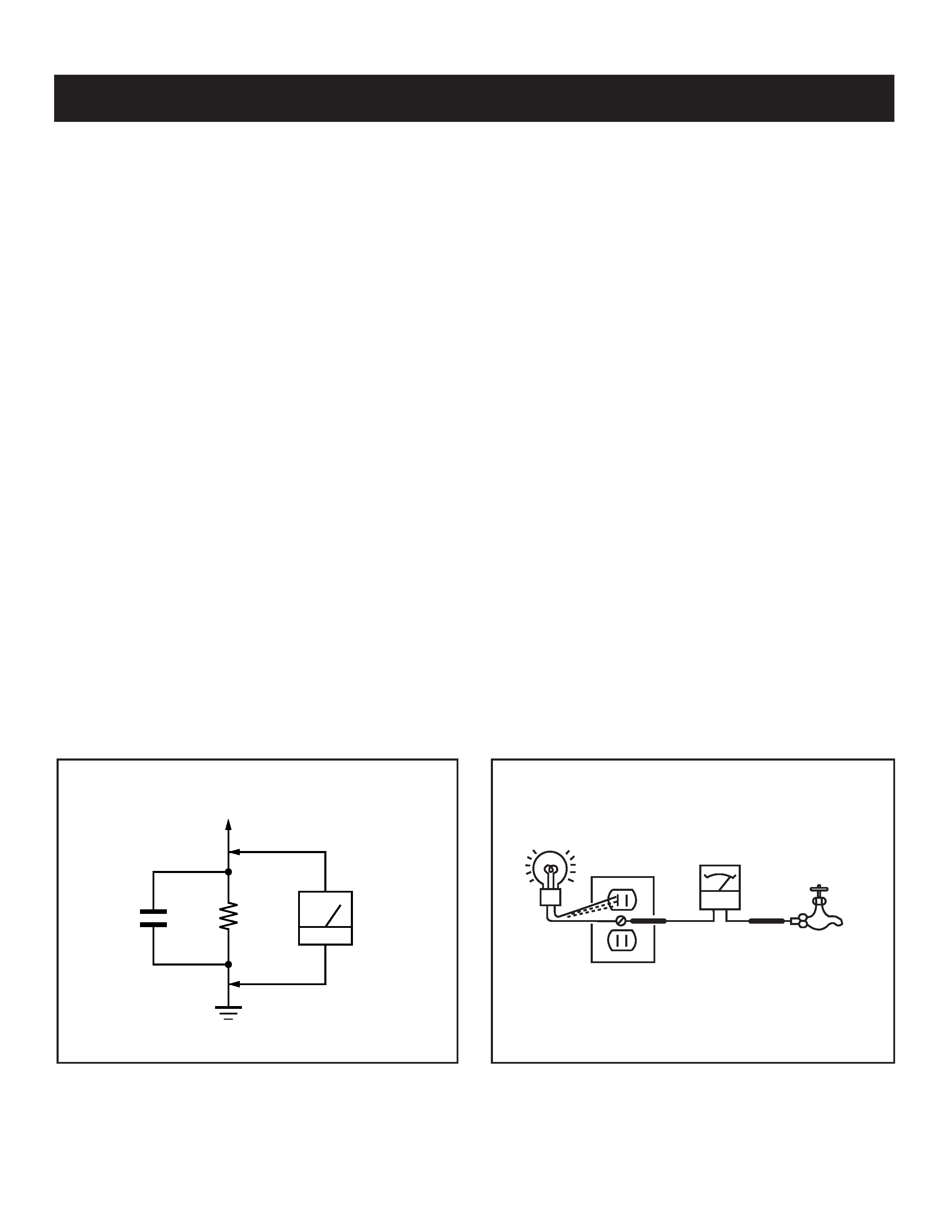
that have a 2 VAC range are suitable (see Figure A).
How to Find a Good Earth Ground
A cold-water pipe is a guaranteed earth ground; the cover-plate retaining
screw on most AC outlet boxes is also at earth ground. If the retaining
screw is to be used as your earth ground, verify that it is at ground
by measuring the resistance between it and a cold-water pipe with an
ohmmeter. The reading should be zero ohms.
If a cold-water pipe is not accessible, connect a 60- to 100-watt trouble-
light (not a neon lamp) between the hot side of the receptacle and the
retaining screw. Try both slots, if necessary, to locate the hot side on the
line; the lamp should light at normal brilliance if the screw is at ground
potential (see Figure B).
To Exposed Metal
Parts on Set
AC Voltmeter
(0.75 V)
Earth Ground
0.15
µF
1.5 k
g
AC Outlet Box
Ohmmeter
Cold-water Pipe
Figure A. Using an AC voltmeter to check AC leakage.
Figure B. Checking for earth ground.
-- 5 --
SAT-T60
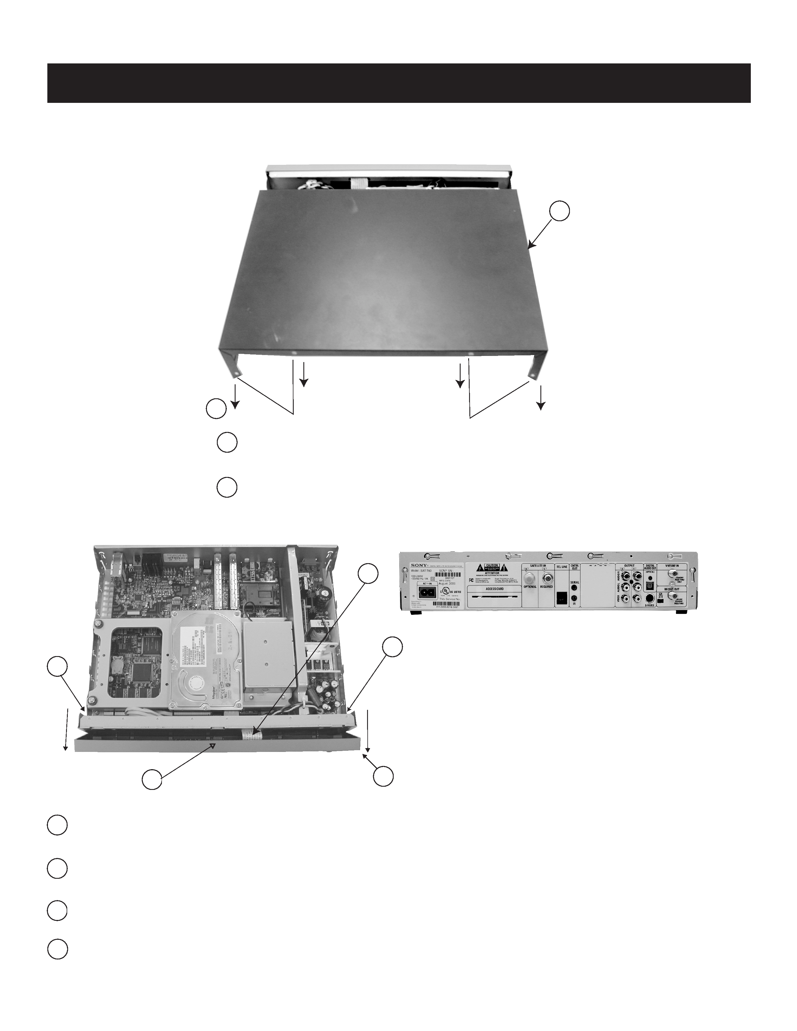
1-1. TOP COVER REMOVAL
1-2. FRONT PANEL REMOVAL
1-3. BACK PANEL INFORMATION
SECTION 1: DISASSEMBLY
Remove 4 screws (Type #m 3 x 0.5 x 6, PH, TORX) from rear of cover.
Carefully pull cover towards back of unit to release and remove.
Pull panel forward to release.
Press down on middle of panel to loosen clips.
Detach ribbon cable/harness connecting front panel to main board.
Remove (2) screws (+BVTP 3 x 8 Type 2 IT-3)
NOTE: Most units will only contain a single HDD
1
1
2
2
1
2
4
4
3
3
1
2
1