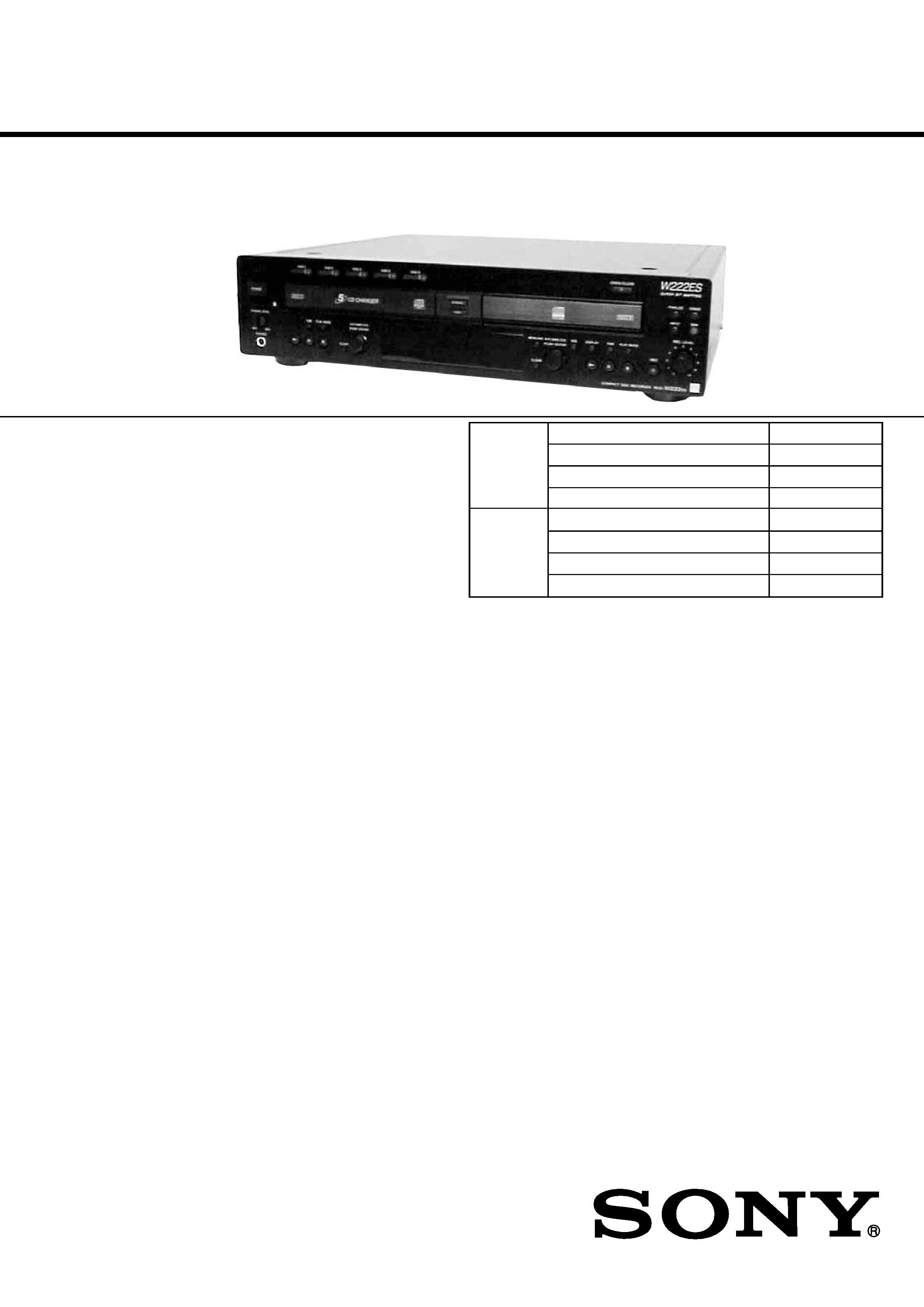
RCD-W222ES
US Model
COMPACT DISC RECORDER
SERVICE MANUAL
SPECIFICATIONS
Model Name Using Similar Machanism NEW
CD Mechanism Type
CDM65-RBD1
Base Unit Name
RBD1
Optical Pick-up Name
KRS-220C
Model Name Using Similar Mechanism NEW
CD Mechanism Type
CDM53L-30B61B
Base Unit Name
BU-30BBD61B
Optical Pick-up Name
A-MAX.3
CD-R
section
CDP
section
9-874-116-01
2002I0200-1
© 2002.09
Sony Corporation
Home Audio Company
Published by Sony Engineering Corporation
Ver 1.0 2002.09
DECK A (the CD player section)
System
Compact disc digital audio system
Laser
Semiconductor laser (
=780 nm)
Emission duration: continuous
Frequency response
20 Hz 20,000 Hz (
±0.5 dB)
Wow and flatter
Below measurable limit
DECK B (the CD-R and CD-RW recording section)
System
Compact disc digital audio system
Laser
Semiconductor laser (
=780 nm)
Emission duration: continuous
Playable discs
CD, CD-R, CD-RW
Recordable discs
CD-R, CD-RW (for music use)
Frequency response
20 Hz - 20,000 Hz (
±0.5 dB)
Wow and flatter
Below measurable limit
Inputs
ANALOG IN
(Phono jacks)
Impedance: 47 kilohms
Rated input: 500 mVrms
Minimum input: 250 mVrms
DIGITAL OPTICAL IN
(Square optical connector jack)
Optical wavelength: 660nm
DIGITAL COAXIAL IN
(Phono jack)
Impedance: 75 ohms
Rated input: 0.5 Vp-p,
± 20 %
Outputs
ANALOG OUT
(Phono jacks)
Impedance: 47 kilohms
Rated output: 2 Vrms
Load impedance: over 10 kilohms
DIGITAL OPTICAL OUT
(Square optical connector jack)
Optical wavelength: 660nm
Rated output: 18 dBm
DIGITAL COAXIAL OUT
(Phono jack)
Rated output: 0.5 Vp-p,
± 20 %
Load impedance: 75 ohms
PHONES
(Stereo phono jack)
Rated output: 28mW
Load impedance: 32 ohms
General
Power requirements
120 V AC, 60 Hz
Power consumption
29 W
Dimensions (approx.) (w/h/d) incl. projecting parts and control
430 x 110 x 400 mm
( 17 x 4 3/8 x 15 3/4 inch)
Mass (approx.)
7.5 kg (16 1/2 lbs)
Supplied accsessories
· Audio connecting cords
Phono jack x 2 (red/white)
y Phono jack x 2 (red/white) (2)
· Remote commander (remote) (1)
· Size AA (R6) batteries (2)
Design and specifications are subject to change
without notice.

2
RCD-W222ES
SAFETY CHECK-OUT
After correcting the original service problem, perform the follow-
ing safety checks before releasing the set to the customer:
Check the antenna terminals, metal trim, "metallized" knobs, screws,
and all other exposed metal parts for AC leakage. Check leakage as
described below.
LEAKAGE
The AC leakage from any exposed metal part to earth Ground and
from all exposed metal parts to any exposed metal part having a
return to chassis, must not exceed 0.5 mA (500 microampers). Leak-
age current can be measured by any one of three methods.
1. A commercial leakage tester, such as the Simpson 229 or RCA
WT-540A. Follow the manufacturers' instructions to use these
instruments.
2. A battery-operated AC milliammeter. The Data Precision 245
digital multimeter is suitable for this job.
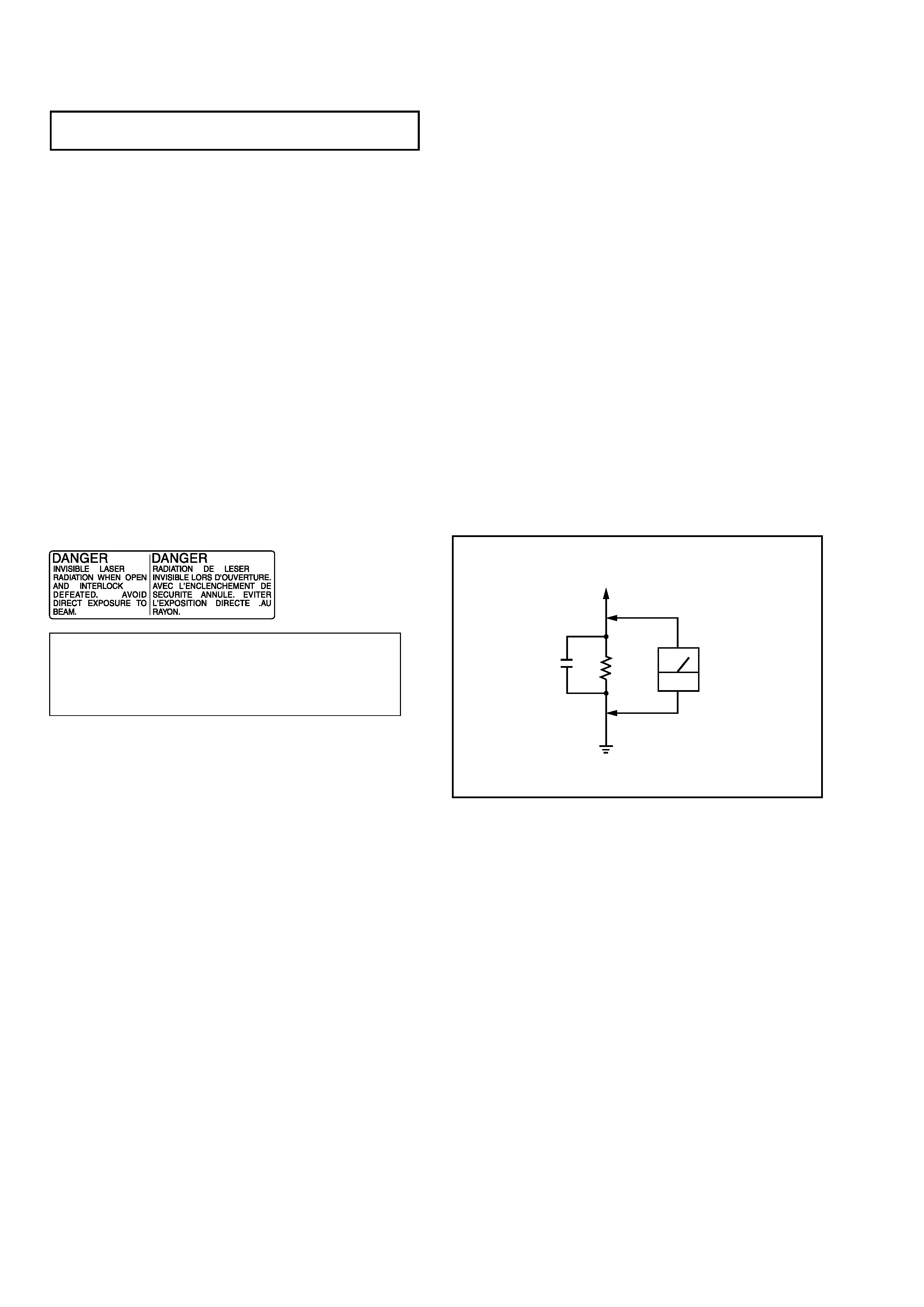
3. Measuring the voltage drop across a resistor by means of a VOM
or battery-operated AC voltmeter. The "limit" indication is 0.75
V, so analog meters must have an accurate low-voltage scale.
The Simpson 250 and Sanwa SH-63Trd are examples of a pas-
sive VOM that is suitable. Nearly all battery operated digital
multimeters that have a 2V AC range are suitable. (See Fig. A)
SAFETY-RELATED COMPONENT WARNING !!
COMPONENTS IDENTIFIED BY MARK ! OR DOTTED LINE
WITH MARK ! ON THE SCHEMATIC DIAGRAMS AND IN
THE PARTS LIST ARE CRITICAL TO SAFE OPERATION.
REPLACE THESE COMPONENTS WITH SONY PARTS
WHOSE PART NUMBERS APPEAR AS SHOWN IN THIS
MANUAL OR IN SUPPLEMENTS PUBLISHED BY SONY.
Notes on chip component replacement
· Never reuse a disconnected chip component.
· Notice that the minus side of a tantalum capacitor may be
damaged by heat.
Flexible Circuit Board Repairing
· Keep the temperature of soldering iron around 270°C
during repairing.
· Do not touch the soldering iron on the same conductor of the
circuit board (within 3 times).
· Be careful not to apply force on the conductor when soldering
or unsoldering.
NOTES ON HANDLING THE OPTICAL PICK-UP
BLOCK OR BASE UNIT
The laser diode in the optical pick-up block may suffer electrostatic
break-down because of the potential difference generated by the
charged electrostatic load, etc. on clothing and the human body.
During repair, pay attention to electrostatic break-down and also
use the procedure in the printed matter which is included in the
repair parts.
The flexible board is easily damaged and should be handled with
care.
NOTES ON LASER DIODE EMISSION CHECK
The laser beam on this model is concentrated so as to be focused on
the disc reflective surface by the objective lens in the optical pick-
up block. Therefore, when checking the laser diode emission, ob-
serve from more than 30 cm away from the objective lens.
CAUTION
Use of controls or adjustments or performance of procedures
other than those specified herein may result in hazardous ra-
diation exposure.
Fig. A. Using an AC voltmeter to check AC leakage.
0.15µF
To Exposed Metal
Parts on Set
1.5k
AC
voltmeter
(0.75V)
Earth Ground
CAUTION
The use of optical instruments with this product will increase eye
hazard.As the laser beam used in this Compact Disc Recorder is
harmful to eyes, do not attempt to disassemble the cabinet.
Refer servicing to qualified personnel only.
The following caution label is located inside the apparatus.

3
RCD-W222ES
TABLE OF CONTENTS
1. SERVICING NOTE .......................................................... 4
2. GENERAL .......................................................................... 7
3. DISASSEMBLY
3-1. Case (Top) ............................................................................ 8
3-2. Front Panel Section .............................................................. 9
3-3. Power SW board, HP board, RM board,
LED board, CD SW board, Display Board .......................... 9
3-4. Deck A (CDM53L-30B61B), Deck B (CDM65-RBD1) ... 10
3-5. CD-R Board, Tray And Optical Pick-Up Block
(KRM-220) (Deck B) ......................................................... 11
3-6. CD Base Unit (BU-30BBD61B) (Deck A) ........................ 12
3-7. Fitting Base (Guide) Assy, Bracket (Chassis)
And Magnet Assy (Deck A) ............................................... 12
3-8. Tray (Sub) (Deck A) .......................................................... 13
3-9. Chassis (Mold B) Section, Stocker Section
And Slider (Selection) ........................................................ 13
4. ASSEMBLY ....................................................................... 14
5. TEST MODE ...................................................................... 17
6. ELECTRICAL ADJUSTMENT ................................... 20
7. DIAGRAMS
7-1. Circuit Boards Location .................................................... 51
7-2. Block diagrams BD Section ........................................ 52
Block diagrams CD-R Section .................................... 53
Block diagrams MAIN Section ................................... 54
7-3. Schematic Diagram CD-R (1/3) Section ..................... 55
7-4. Schematic Diagram CD-R (2/3) Section ..................... 56
7-5. Schematic Diagram CD-R (3/3) Section ..................... 57
7-6. Printed Wiring Board CD-R Section (Side A) ............ 58
Printed Wiring Board CD-R Section (Side B) ............ 59
7-7. Printed Wiring Board BD Section ............................... 60
7-8. Schematic Diagram BD Section ................................ 61
7-9. Printed Wiring Board CDM Section ........................... 62
7-10. Schematic Diagram CDM Section ............................. 63
7-11. Printed Wiring Board MAIN Section (Side A) ........... 64
Printed Wiring Board MAIN Section (Side B) ........... 65
7-12. Schematic Diagram MAIN (1/2) Section ................... 66
7-13. Schematic Diagram MAIN (2/2) Section ................... 67
7-14. Printed Wiring Board LED, HP Section ...................... 68
7-15. Schematic Diagram LED, HP Section ....................... 69
7-16. Printed Wiring Board Display, Power Section ............ 70
7-17. Schematic Diagram Display, Power Section ............... 71
7-18. IC Pin Functions ................................................................ 72
7-19. IC Block Diagrams ............................................................ 83
8. EXPLODED VIEWS
8-1. Case Section ........................................................................ 85
8-2. Front Panel Section ............................................................. 86
8-3. Chassis Section ................................................................... 87
8-4. CD Play Mechanism Section (Deck A)-1
(CDM53L-30B61B) ........................................................... 88
8-5. CD Play Mechanism Section (Deck A)-2
(CDM53L-30B61B) ........................................................... 89
8-6. CD Play Mechanism Section (Deck A)-3
(CDM53L-30B61B) ........................................................... 90
8-7. Stocker Overall, Optical Pick-Up Section (Deck A) .......... 91
8-8. Base Unit (Deck A) ............................................................. 92
8-9. CD-R Mechanism Deck Section (Deck B) ......................... 93
9. ELECTRICAL PARTS LIST
................................. 94
SELF-DIAGNOSIS FUNCTION
When the self-diagnosis function is activated to prevent the player from
malfunctioning, three character service numbers in a combination with a
message appears in the display. In this case, check the following table.
Message
Explanation
C12/
You are trying to record a disc that cannot be played
Cannot Copy
back in DECK-A or with an external device, such
as CD-ROM or VIDEO CD.
· Remove the disc, and then insert a music CD for
playback.
C13/
Recording has not been completed successfully be-
Rec Error
cause of vibration.
· Relocate the unit in a place free of vibration and
restart the recording again.
The disc you try to record is excessively dirty (such
as oilstained or finger marked) or scratched. Or the
disc is not normal.
· Replace the disc with another one and restart the
recording again.
C14/
The unit did not read the TOC information.
TOC Error
· Insert other discs.
C41/
The sound source you are trying to record is a copy
Cannot Copy
of a commercial music software. Or you are trying
to record on a CD-R/CD-RW digitally.
· Because of the restriction of the Serial Copy Man-
agement System, you cannot record a copy of a
commercial music software.
Neither can you record a CD-R/ CD-RW digitally.
· Use analog recording through the ANALOG IN
jack when you record from other units. Or use Syn-
chro-Recording when you record from DECK A.
(The recording mode is automatically changed to
analog recording.)
C71/
If this message is displayed momentarily, this is not
Din Unlock
an error. It is caused by the digital signal during re-
cording.
During recording of a digital sound source, the con-
necting cable has been disconnected or the player of
the sound source has turned off.
· Connect the cable or turn on the digital player.

4
RCD-W222ES
SECTION 1
SERVICING NOTE
NOTES REGARDING HANDLING OF THE PICK-UP
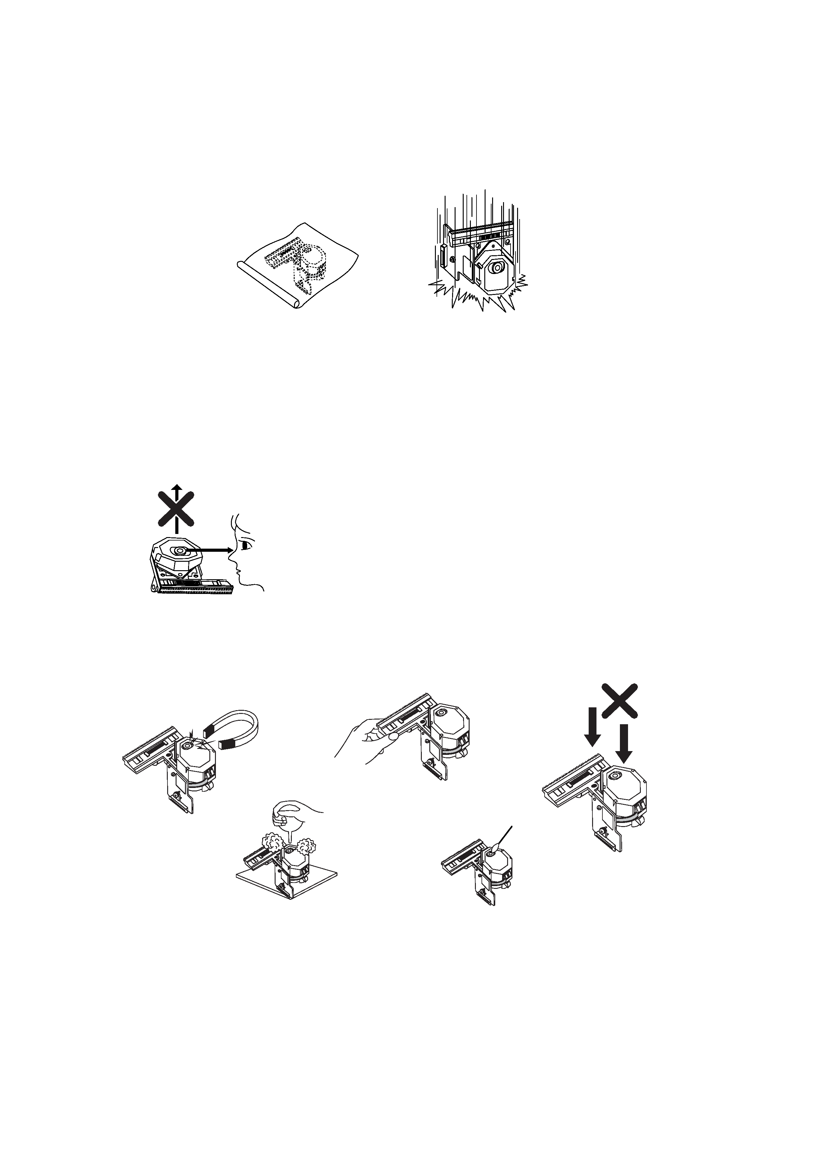
1. Notes for transport and storage
1) The pick-up should always be left in its conductive bag until immediately prior to use.
2) The pick-up should never be subjected to external pressure or impact.
2. Repair notes
1) The pick-up incorporates a strong magnet, and so should never be brought close to magnetic materials.
2) The pick-up should always be handled correctly and carefully , taking care to avoid external pressure and impact.
If it is subjected to pressure or impact, the result may be an operational malfunction and/or damage to the
printed-circuit board.
3) Each and every pick-up is already individually adjusted to a high degree of precision, and for that reason the
adjustment point and installation screws should absolutely never be touched.
4) Laser beams may damage the eyes!
Absolutely never permit laser beams to enter the eyes!
Also NEVER switch ON the power to the laser output part (lens, etc.) of the pick-up if it is damaged.
5) Cleaning the lens surface
If there is dust on the lens surface, the dust should be cleaned away by using an air bush (such as used for
camera lens). The lens is held by a delicate spring. When cleaning the lens surface, therefore, a cotton swab
should be used, taking care not to distort this.
6) Never attempt to disassemble the pick-up.
Spring by excess pressure. If the lens is extremely dirty, apply isopropyl alcohol to the cotton swab. (Do not use any
other liquid cleaners, because they will damage the lens.) Take care not to use too much of this alcohol on the swab,
and do not allow the alcohol to get inside the pick-up.
Storage in conductive bag
NEVER look directly at the laser beam, and don't let contact
fingers or other exposed skin.
Magnet
How to hold the pick-up
Conductive Sheet
Cotton swab
Pressure
Pressure
Drop impact

5
RCD-W222ES
NOTES REGARDING COMPACT DISC PLAYER REPAIRS
1. Preparations
1) Compact disc players incorporate a great many ICs as well as the pick-up (laser diode). These compo-
nents are sensitive to, and easily affected by, static electricity. If such static is high voltage, components
can be damaged, and for that reason components should be handled with care.
2) The pick-up is composed of many optical components and other high-precision components. Care must
be taken, therefore, to avoid repair or storage where the temperature of humidity is high, where strong
magnetism is present, or where there is excessive dust.
2. Notes for repair
1) Before replacing a component part, first disconnect the power supply lead wire from the unit
2) All equipment, measuring instruments and tools must be grounded.
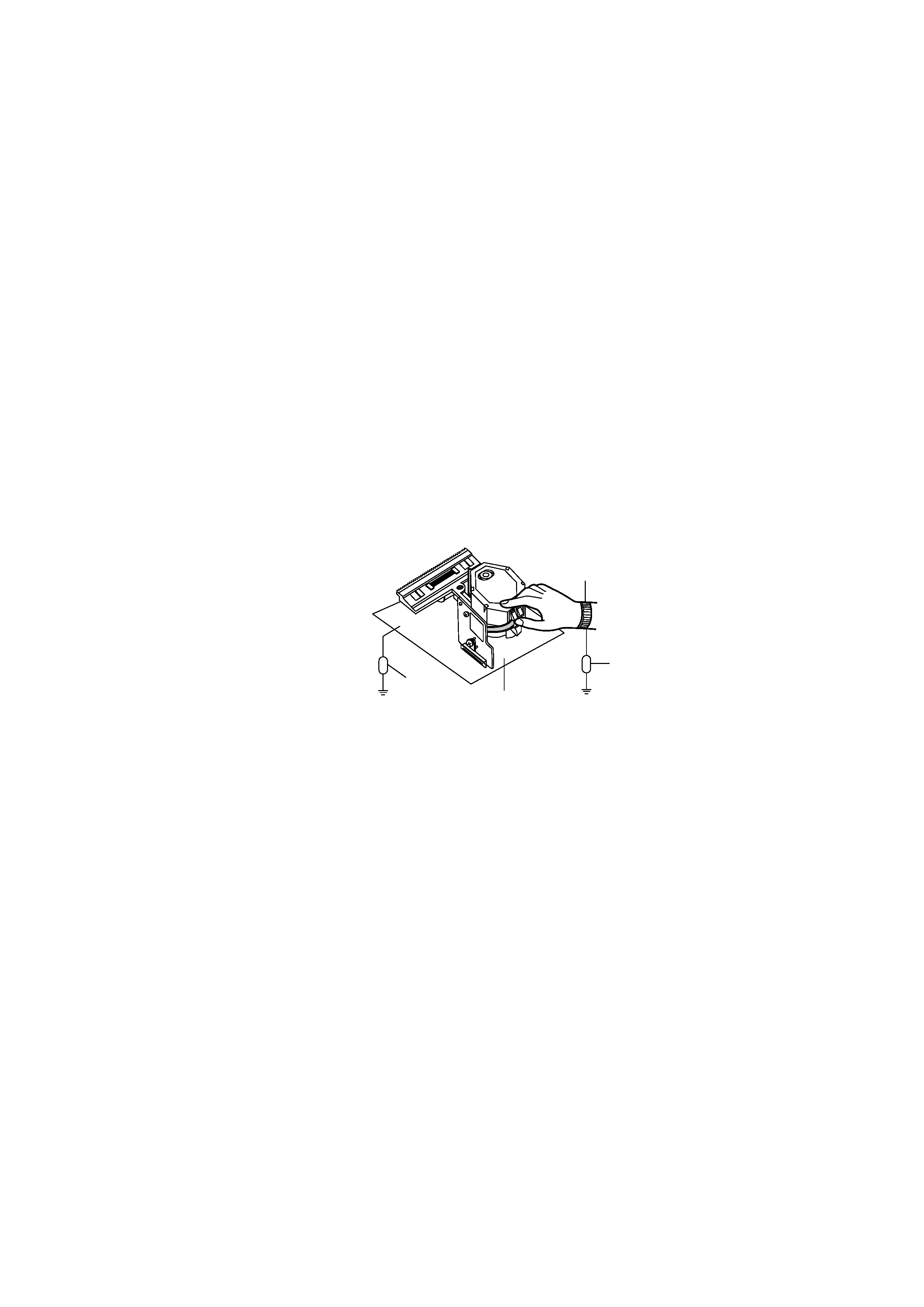
3) The workbench should be covered with a conductive sheet and grounded.
When removing the laser pick-up from its conductive bag, do not place the pick-up on the bag. (This is
because there is the possibility of damage by static electricity.)
4) To prevent AC leakage, the metal part of the soldering iron should be grounded.
5) Workers should be grounded by an armband (1M
)
6) Care should be taken not to permit the laser pick-up to come in contact with clothing, in order to prevent
static electricity changes in the clothing to escape from the armband.
7) The laser beam from the pick-up should NEVER be directly facing the eyes or bare skin.
Resistor
(1M
)
Conductive
Sheet
Resistor
(1M
)
Armband
